COP Security 15-QC42 User manual

COLOR QUAD VIDEO PROCESSOR
USER MANUAL
MODEL: 15-QC42

INDEX
1. Important Safeguards --------------------------- Page 2
2. Introduction-------------------------------------------- Page 3
3. Outline--------------------------------------------------- Page 4
4. Installation --------------------------------------------- Page 5
5. Operating Procedure------------------------------- Page 7
6. VCR Playback Mode-------------------------------- Page 8
7. Setup Menu-------------------------------------------- Page 9
8. Alarm Port----------------------------------------------- Page 12
9. Specification------------------------------------------- Page 13
IMPORTANTSAFEGUARDS
1. Read manual thoroughly before setup or operation of this product.
2. Save this booklet for further reference.
3. Follow the instructions and heed all warning notices.
4. Do not liquid or aerosol cleaners on this product, use a slightly damp cloth only.
Do this only with the unit unplugged from the power source.
5. Do not use accessories not recommended by your dealer or installer with this unit.
6. Keep unit in a dry location. Dampness or moisture will be damage the internal
components.
7. Do not block ventilation openings on unit.
8. Never insert any objects into unit, this could result in fire or electric shock.
Never spill any liquid onto or into unit.
9. If an outdoor cable is connected to this unit, be sure the cable is grounded well.
10. For added protection of this unit during a lightning or electrical storm, or when it
is left unused for a long period of time, unplug it from the wall outlet and
disconnect all cables.
WARNING : Cover removal should only be performed by qualified service personnel.
This unit contains no user serviceable parts.
2

Introduction
Your new quad processor offers high performance with a wide range of features,
including:
⊙Built-in high performance digital video processor which meet CCIR-601 digital
video standard.
⊙In VCR playback mode this unit provide 2X2 zooming and hold still picture on
monitor.
⊙User can set different input video brightness, contrast, hue, saturation individually..
⊙Built-in real-time generator.
⊙Built-in OSD to display date/time, titles and system alarm event.
⊙Auto detect and display video loss.
⊙With alarm port for other security system application.
BACK PANEL
MENU
/VCR
QUAD
/ SEQ
1.SETUP MENU/VCR MODE 4.SELECT ITEM (in menu)
2.QUAD MODE/SEQUENTIAL 5.CHANGE STATUS (in menu)
3.CAMERA SELECT
FRONT PANEL
2-CH 3-CH 4-CH MONITOR VCR OUT
ALARM
DC IN
VIDEO IN
VCR IN
1.VIDEO IN (1~4) 4.ALARM PORT
2.MONITOR OUT 5.POWER IN (DC +12V)
3.VCR OUT (for VCR record) 6.VCR IN (for VCR playback)
43

Installation
NOTE : Please make sure to unplug power before connect any cable to this unit.
1. Place this unit on a flat, stable surface. Avoid locations that are subject to direct
sunlight, excessive heat, moisture, or dust.
2. Connect the cables that come from cameras to VIDEO IN ports, the input
impedance of these ports are 75 ohms.
3. Connect VCR IN/ OUT to VCR OUT/IN of VCR to record the picture.
4. Connect MONITOR OUT to VIDEO IN of monitor.
5. Connect ALARM to other equipment by 9 pins D-SUB connecter. Definition of
this port will be described in page 12.
6. After user complete all the connection, plug the adaptor in.
ONE VCR SETUP FOR MONELS
2-CH 3-CH 4-CH MONITOR VCR OUT
ALARM
DC IN
VIDEO IN
VCR
ALARM SENSOR
MONITOR
VCR IN
PLAY BACK MODELOS
2-CH 3-CH 4-CH MONITOR VCR OUT
ALARM
DC IN
VIDEO IN
VCR
ALARM SENSOR
MONITOR
VCR IN
65

Operating procedure
QUAD MODE
Press the QUAD key will get into this mode, the monitor and the VCR OUT port will
output QUAD.
SINGLE CAMERA MODE
In this mode, monitor output port will output the camera picture that user selected.
The VCR OUT port will output QUAD.
Press the number in CAMERA SELECT key will get into this mode.
SEQUENTIAL CAMERA MODE
Press the SEQ key 1 second in this mode, monitor port will output the sequential
camera picture in the interval user set. This unit will skip the camera inputs that are no
signal automatically. The VCR OUT port will output QUAD.
VCR PLAYBACK MODE
Press the VCR key 1 second into PLAYBACK MODE.
Before get into this mode, please make sure that VCR IN / OUT has correct input
signal.
2X2 ZOOMING and HOLD
After into PLAYBACK MODE, user can press one of the number “1” to “4” key to
get into 2X2 zooming mode to watch 2X2 zooming picture of the playback picture.
“1” will zooming the camera 1 in playback picture, “2” will zooming camera2,
“3” will zooming camera 3, “4” will zooming camera 4.
Press the same number key again will hold the zoomed playback picture.
Press the same number key again will release the zoomed playback picture.
Press QUAD key will back to full screen playback picture.
Press VCR key again will exit the VCR PLAYBACK MODE.
87

Setup menu
Press the MENU key will get into setup menu.
There have 4 setup pages, press the MENU key repetitious to change the menu pages.
Use keys “←” or “→” to select the item that want to change, then use “+” or “ ―”
keys to change the value or status.
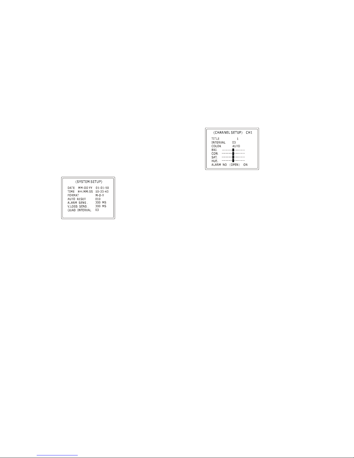
1st OSD menu
AUTO RESET : Every time there has an ALARM or V.LOSS event, it will trigger an
internal counter. When the counter reach the value that user set this
unit will clear the event automatically.(unit : second)
User can clear the event by press any key.
ALARM SENS.: The ALARM event will not occur unless the ALARM trigger is
longer than what user set.(Unit : millisecond)
V.LOSS SENS.: The V.LOSS event will not occur unless the V.LOSS trigger is longer
than what user set.(Unit : millisecond)
QUAD INTERVAL : The timing for sequential QUAD MODE. (Unit : second)
2nd OSD menu
CH : Select the input channel user want to set.
TITLE : 6 characters can be set for each channel.
INTERVAL : The timing for sequential CAMERA MODE.
COLOR : Color killer, default is AUTO. If the video signal of selected channel is with
very low chroma level, it must be set to FIX to disable the automatic
chroma remover. It usually happened with a very long cable connection of
the length will depend on the specification of cable.
BRI. : Adjust the brightness of input video.
CON. :Adjust the contrast of input video.
SAT. : Adjust the saturation of input video.
HUE : Adjust the hue of input video.
ALARM : There has three parts of this item.
1st one is to set the type of external alarm equipment. (NC or NO)
2ND one is the status detected by this unit in power-on initialization. (OPEN or
CLOSE)
3rd one is to enable or disable ALARM trigger of this channel. (ON or OFF)
109

3rd OSD menu
QUAD: Enable or disable to display date, time, title on “VCR OUT” port.
V. LOSS : Enable or disable this unit to check video loss event.
4th OSD menu
P : Select the page number of alarm record. There have 11 pages and 9 records in each
page, total can save 99 records maximum.
There has 4 parts if each records, first one indicate ALARM or V. LOSS event and
then followed by channel number, date, and time.
ALARM port
54321
9876
1. COM
2. N.O.
3. N.C.
4. GND
5. ALARM CONTROL
6. CH1 ALARM
7. CH2 ALARM
8. CH3 ALARM
9. CH1 ALARM
NOTE : The ALARM input 1 to 4 and clear input are pull high internally. Connect the
this unit will detect the type of external alarm equipment automatically in power-on
initialization.
The internal relay was set to N.C. position normally. So the pin 1 and 3 was short
normally, and will be opened when an event was occur.
The pin 2 was open normally, and will be closed when an event occur.
WARING : The rating of internal relay is : AC 120V 1A or DC 30V 1A. User must
not overload the relay for safety reason.
1211

Specifications
SMAPING RATE 910 pixels per line for NTSC
1135 pixels per line for PAL
TOTAL PIXLS PER LINE 858 H pixels for NTSC
864 H pixels for PAL
DISPLAY RATE 60 fields/second real-time refresh rare
CAMERE INPUTS composite video 1 Vp-p, 75 Ω
VCR IN/OUT 1 BNC, composite video 1 Vp-p, 75 Ω
MONITOR OUTPUTS 1 BNC, composite video 1 Vp-p, 75 Ω
ALARM INPUT/OUTPUT 9-pins D-SUB female connector
OPERATION TEMPERATURE 5OC to 45 OC
RELAIVE HUMIDITY 5% to 85%(non-condensing)
POWER SOURCE 12V DC 1A
13
Table of contents