Clarion
Malaysia
Sdn. Bhd.
Clarion
«~~
Phase
1,
FTZ,
Bayan
Lepas,
11900
Penang.
Tai:
(04)
6439106/7
Fax:
(04)
6439108
Export
Divison
-
22-3,
Shibuya2-chome,Shibuyaku,
Tokyo,
150
Japan
Tel:03-3400-1121"
Service
Manual
Published
by
Clarion
Malaysia
Printed
in
Malaysia
Mar
1997
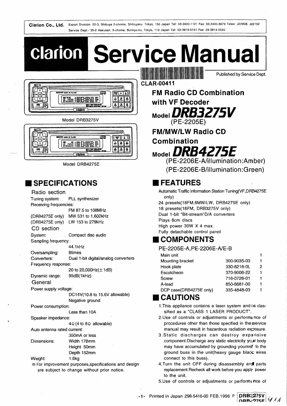
FM-MPX
Radio
CD
Combi
with
VF
Decoder
voce:
DRB3375V
(PE-2244E)
FM-MPX/MW/LW
Radio
CD
Combi
modet
DRB3376E
(PE-2245E-A/illumination:Amber)
(PE-2245E-B/illumination:Green)
M@
ORIGINAL
SERVICE
MANUAL
This
additional
service
manual
is
designed
to
be
used
together
with
Model
DRB3275V/DRB4275E
Original
mode
DRB3275V/DRB4275E
298-5416-00
+44
mM
SPECIFICATIONS
Radio
Section
Tuning
system:
Receiving
frequencies:
(DRB3376E
only)
(DRB3376E
only)
CD
section
System:
Sampling
frequency:
Oversampling:
Converters:
Frequency
response:
Dynamic
range:
General
Power
supply
voltage:
Power
consumption:
PLL
synthesizer
FM
87.5
to
108MHz
MW
531
to
1,602kHz
LW
153
to
279kKHz
Compact
disc
audio
44.1kHz
8
times
Dual
1-bit
digital/analog
converters
20
to
20kHz(+1dB)
95dB(1kHz)
DC14V
(10.8
to
15.6V
allowable)
Negative
ground
Less
than
10A
Speaker
impedance:
Auto
antenna
rated
current:
4Q
(4
to
8Q
allowabie)
350mA
or
less
178(W)
x
50(H}x
152(D)
1.6kg
(3.52Ib)
Dimensions
(mm):
Weight:
m@
FEATURES
1.
Automatic
Traffic
Information
Station
Tuning
(VF,
ORB3375V
only)
2.
24
presets
(18FM,6MW/LW,
DRB3376E
only)
3.
18
presets
(18FM,DRB3375V
only)
4.
Dual
1-bit
"Bit-stream”
D/A
converters
5.
Plays
8cm
discs
6.
High
power
30W
x
4
ch
max.
7.
Fully
detachable
control
panel
Mi
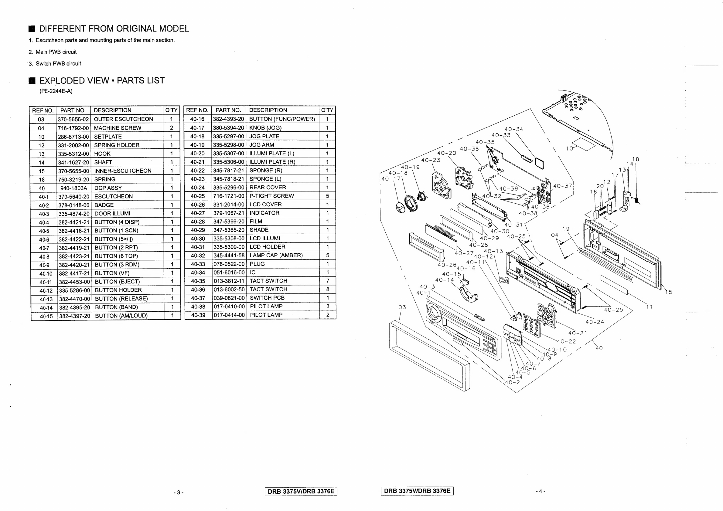
COMPONENTS
PE-2244E-A,PE2245E-A/E-B
Main
unit
————
1
Mounting
bracket
300-9035-03
1
Hook
plate
330-8216-0L
2
Outer
Escutcheon
370-5656-02
4
Screw
716-0726-01
1
DCP
case
335-5331-00
4
Spacer
345-3653-01
1
%*
For
improvement
purposes,
specifications
and
desig:
awe
subject
to
change
without
prior
notice.
DRB
3375V/DR3
3376E