2
SPECIFICATIONS
Applications
The 45 Ohm talkback speakers are designed to be
used with "handsfree" talkback control units. In
combination with these units, the speakers provide
both loudspeaker and talkback functions.
Environment
•Temperature: -20 to +55 Degrees C
•Humidity: 0 to 95% non-precipitating
Power Requirements
•None
Coverage
The distance you can be away from a speaker and still
have good talkback depends on the type of speaker
and ambient noise level. In a typical office
environment, these speakers will cover approximately
600 square feet (Talkback from 25').
Remember: The speaker is no better than your ears.
If you cannot carry on a conversation at normal voice
levels over the required talkback distance, then
talkback page equipment will not function
satisfactorily.
The speaker should be as close as possible to the
area where talkback is desired. It should not be
mounted close to, or pointed at, noise producing
equipment such asfans, air conditioners, machinery
or compressors.
Limitations
•One talkback speaker maximum per zone when
used with the DL-24A System
•800 feet maximum cable length to speaker
NOTE: Do not split pairs to speakers
•Do not use talkback in noisy areas (80dB or
greater)
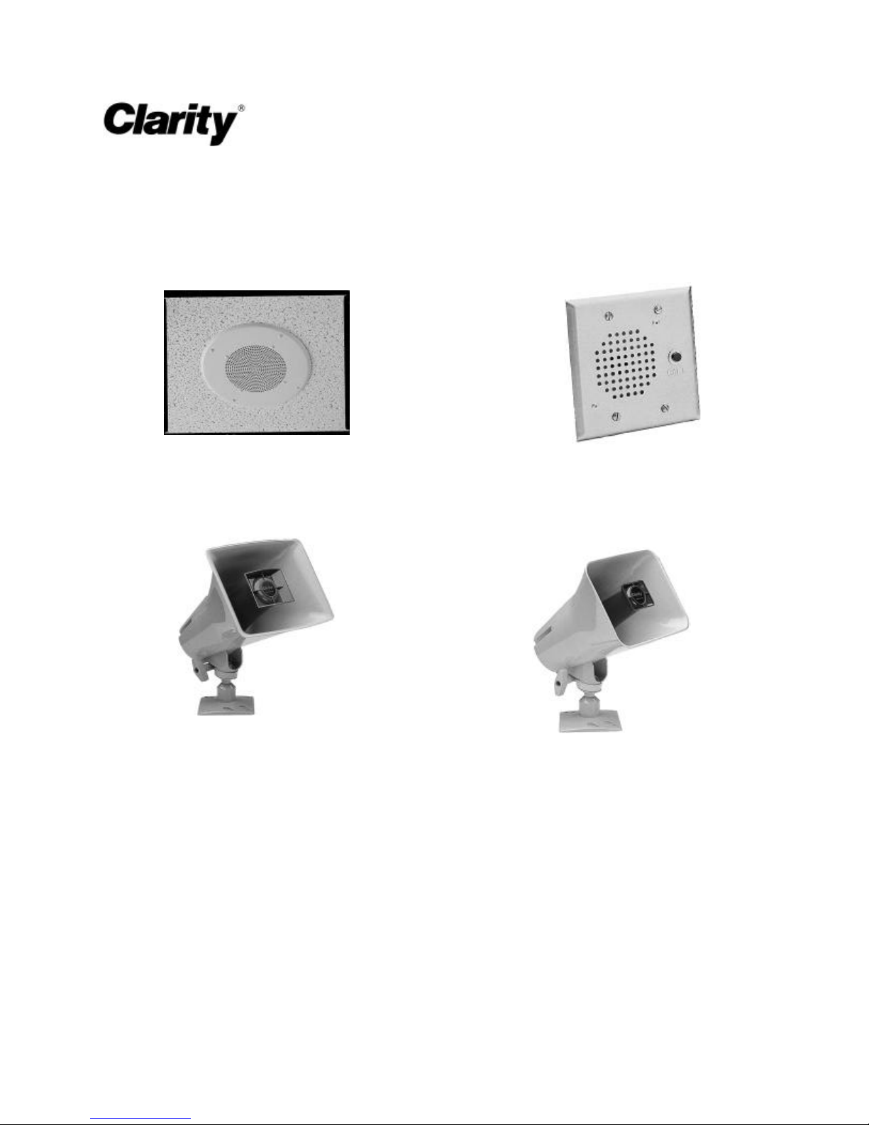
Individual Units -
S-503 -Ceiling Speaker
The S-503 is a Ceiling Speaker designed to be used
with "handsfree" talkback control units. This speaker
is for interior use only and measures approximately
13" diameter x 3" deep.
Features:
•45 Ohmimpedance
•Eight inch speaker
•Easy hook-up (Two connections using CAT3 or
better twisted pair cabling)
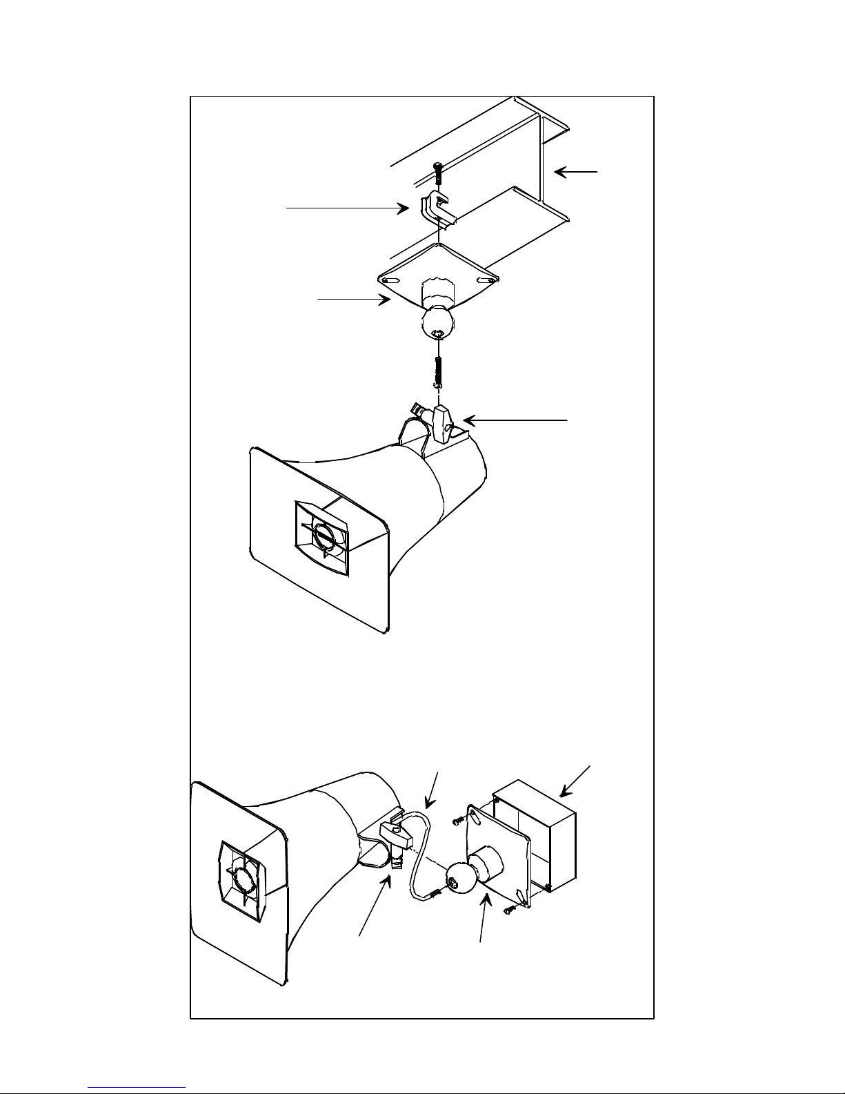
Mounting / Connections:
•To install speaker assembly, measure and cut an
8.5" hole in center of ceiling tile (If using a S-
550 and S-551, Bridge and Backbox, cut a 10" hole
in center of ceiling tile).
•Mount speaker as close to primary talkback area
as possible. Ideal mounting height should be
between 7 and 23 feet.
•Connect station or other suitable wire to proper
speaker terminals per Figure 1.
S-570 -Doorplate Speaker
The S-570 is a Doorplate Speaker used to provide
handsfree talkback from an outside door or entryway
location. It is equipped with a push-button switch for
connection to customer provided signaling
equipment.
The doorplate speaker measures 4.5"W x 4.5"H x 2"D
and mounts to a 2-gang 4" x 4" electrical box.
Features:
•45 Ohm input impedance
•SPDT switch contacts rated at 1 Amp
•Easy hook-up using CAT3 or better twisted pair
cabling (Cable runs should be limited to 800 feet)
Mounting / Connections:
•Connect speaker out from page control to
speaker Tip. Speaker common to speaker Ring.
•Connect push-button switch to customer
provided signaling equipment (See Figure 2).
•Mount the doorplate speaker to the electrical box
at a convenient height for talkback.