manuals.online logo
Brands
  1. Home
  2. •
  3. Brands
  4. •
  5. Clarity
  6. •
  7. Speakers
  8. •
  9. Clarity S-525A User manual

Clarity S-525A User manual

Other Clarity Speakers manuals

Clarity S-700 User manual

Clarity

Clarity S-700 User manual

Clarity S-515 User manual

Clarity

Clarity S-515 User manual

Clarity P-TEC S-525 User manual

Clarity

Clarity P-TEC S-525 User manual

Clarity S-530B User manual

Clarity

Clarity S-530B User manual

Clarity S-503 User manual

Clarity

Clarity S-503 User manual

Clarity S-571 User manual

Clarity

Clarity S-571 User manual

Clarity S-520B User manual

Clarity

Clarity S-520B User manual

Clarity S-750 User manual

Clarity

Clarity S-750 User manual

Clarity S-527 User manual

Clarity

Clarity S-527 User manual

Clarity S-527A User manual

Clarity

Clarity S-527A User manual

Clarity S-503 User manual

Clarity

Clarity S-503 User manual

Clarity S-500 User manual

Clarity

Clarity S-500 User manual

Popular Speakers manuals by other brands

Yamaha DXR10 null

Yamaha

Yamaha DXR10 null

argon audio IE20 quick start

argon audio

argon audio IE20 quick start

Denon SC-N7 owner's manual

Denon

Denon SC-N7 owner's manual

Gemline Ace 3952 user manual

Gemline

Gemline Ace 3952 user manual

Focal ON WALL 300 User manua

Focal

Focal ON WALL 300 User manua

HEADRUSH Maximus HRSP 5024 manual

HEADRUSH

HEADRUSH Maximus HRSP 5024 manual

SoundLogic BCCS-6/6395 instruction manual

SoundLogic

SoundLogic BCCS-6/6395 instruction manual

Peavey DTH 218 Specification sheet

Peavey

Peavey DTH 218 Specification sheet

Avantree Pluto Air user guide

Avantree

Avantree Pluto Air user guide

Morel Integra Series INTEGRA OVATION 4 install guide

Morel

Morel Integra Series INTEGRA OVATION 4 install guide

Oppo SONICA quick start guide

Oppo

Oppo SONICA quick start guide

Bose SoundLink Wireless Music System owner's guide

Bose

Bose SoundLink Wireless Music System owner's guide

Rocksteady Stadium owner's manual

Rocksteady

Rocksteady Stadium owner's manual

Bowers & Wilkins 4 owner's manual

Bowers & Wilkins

Bowers & Wilkins 4 owner's manual

Sonance SONOS OUTDOOR Series installation manual

Sonance

Sonance SONOS OUTDOOR Series installation manual

Electro-Voice EVID FM4.2 Brochure & specs

Electro-Voice

Electro-Voice EVID FM4.2 Brochure & specs

Pioneer XW-HTD630 manual

Pioneer

Pioneer XW-HTD630 manual

Onn BWA16AA002 Product guide

Onn

Onn BWA16AA002 Product guide

manuals.online logo
manuals.online logoBrands
  • About & Mission
  • Contact us
  • Privacy Policy
  • Terms and Conditions

Copyright 2025 Manuals.Online. All Rights Reserved.

1 947776
Back Box
(Optional)





P-TEC VOICE PAGING
SPEAKER
S-525A
Issue 1


INTRODUCTION
ClarityP-TECVoicePagingSpeakersare suitable for
voice paging as well as background
music. The
S-525A
is a 25/ 70 Volt modelwith adjustable taps and volume
control. P-TEC speakers consist of a
3.6 inch cone speaker mounted in a unique surface-
mountbaffle. The baffle is designed for mounting on
acoustic tile, such as those normally found in
suspended-ceilings;
and can be mounted without
cutting large holes in the tile. The mounting pins can
be removed for mountingin a hard ceiling. The speaker
housing has screw holes for securingspeakerwithout
mountingpins. Although the P-TEC speakers are
designed especially for standardsuspendedceilings,
they canbe used on many types of ceiling materials.
P-TEC
speake
rs
are not suitable for use in
plenum
ceili
ng
en
vironment
s
.
DIMENSIONS/WEIGHT
• 8.00”Dia. x 2.50”D (20.32cm x 6.35cm)
1.25 lbs. (.57
kg)
INST
ALL
A
TION
Selecting the Power-Tap
W
i
re
1. Remove the Quick-Connect connector from the
accessory pack.
2. Select the desired power-tap wire:
70V Watts 25V Watts Lead Wire
Common Common BLK
.312 -- VIO
.625 -- GRY
1.25 -- BLU
2.5 .312 WHT
5.0 .625 GRY
--Do 1.25 ORG
--Not 2.5 RED
--Use 5.0 BRN

Note: Refer to spacing chart (Figure 6) for
recommended speaker spacing.













Volume
Control


F
i
gure 1. 25/70 Volt P-TEC Paging Speaker

3
. Install the Quick-Connectconnector on the wire.
Use pliers to close the connector over the wire.
The connector can be removed by prying it open
with a screwdriver,and can be reused several
times (See Figure 2).











Reusable
Quick-Connect
Connector

Tap Wire

Figure 2. Attaching the Reuseable Quick-Connect
Connector
2947776
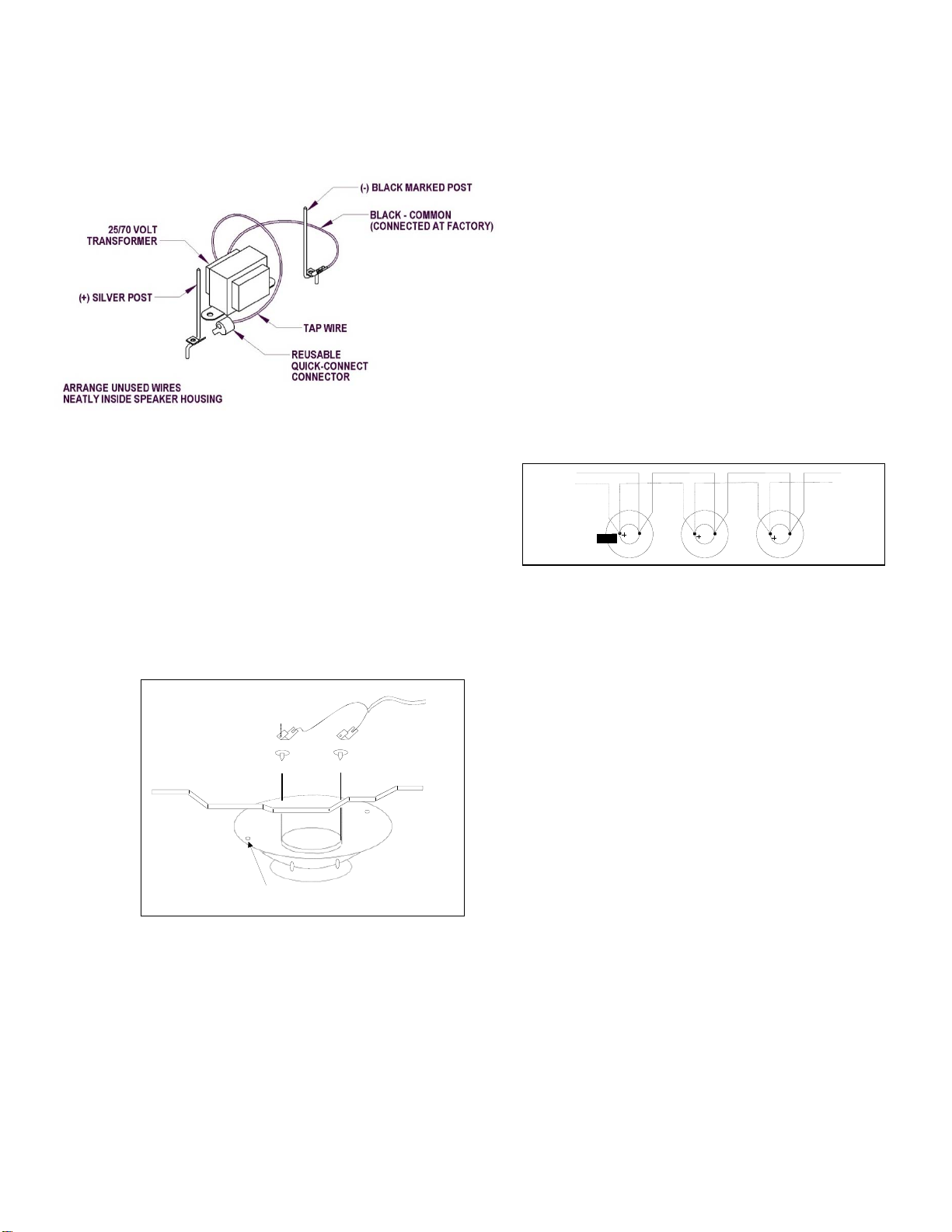
4. Connect the power-tap wire to the silver post (+)
terminal (See Figure 3).
5. Arrange the unused power-tap wires neatly inside
the speaker housing and tape them to the inside
of the housing.

4. If necessary, adjust paging volume after instal-
lation. The volume controlis located on the side of
the speaker. Use a small screwdriverto turn the
control.
5. Install the volume control cover found in the
accessory pack.






.



Note: The music volume should be adjusted at the
paging amplifier or music source.
Adjust pagingbefore adjusting background
music.

Maintain Speaker
Ph
asing
When using multiple speakers in a single run, keep
speakers in phase by connecting the speaker wires to
the same spike on each speaker (Either wire can
connect on either spike, as long as the pattern is
followed on each speaker). The silver
Figure 3. Connecting the Tap Wire
spike is the plus (+) terminal(See Figure 5).

The negative (-) terminal is denoted by a black mark on
the spike.
Suspended
Ceiling
Note: Wrap wires around strain relief posts so
speaker wires will not pull free.

To
Paging
Amplifier

To
Next
Speaker

1
.
Lift the adjacent ceiling tile and slide it out of the
way.
2.
Install the speaker by inserting the mounting pins
through the ceiling tile, and hold the speaker in
place
.
3
.
Place the wire and washers,and speaker
mounting clips over mounting pins (so pins
slide through clips).


To
Amplifier
Red Black
Silver (+)
Figure 5. Maintaining Speaker Phasing

Handling Shielded Speaker
Cable
If you are using shieldedspeaker cable, splice the
shield wire at the speaker location so a continuous
shield is maintained. When connecting a single
speaker, or the last speaker on the run,
clip
the
shield
wire where it emerges from the outer Insulation on the
speaker cable.


silver
Spike

Black
Marked
Spike
TECHNICAL
ASSIS
T
ANCE
When calling, have a VOM and a telephone test set
available and call from the job site.
Call (540) 767-1550 for Clarity Technical Support, or
visit our websites at
http://www.clarity-com.com
and
www.valcom.com.
Use mounting holes and
screws
when spikes can not be
used.
Figure 4. Clarity P-TEC Installation
Note: Washers provide isolation from the pins if the
back of the tile is covered with metal foil.
Should repairs be necessary, attach a tag to the unit
clearly stating companyname, address, phone
number, contact person and the nature of the
problem. Send the unit to:
Clarity
Repair and Return
Dept.
5614 Hollins
Road
Roanoke, VA
24019-5056
3
947776









NOISE
P-TEC SPEAKER PROJECTION DIST
ANCE
SOUND PRESSURE LEVELS AND WATTAGE SETTINGS FOR 70 VOLT
SPK
LEVE
L
IN
dB
55 dB
56 dB
57 dB
58 dB
59 dB
60 dB
61 dB
62 dB
63 dB
64 dB
65 dB
66 dB
67 dB
68 dB
69 dB
70 dB
71 dB
72 dB
73 dB
74 dB
75 dB
76 dB
77 dB
SPL-
76
.25
W
A
TT
26
24
22
20
16
15
14
12
10
8
SPL-
78
.50
W
A
TT
24
22
20
16
15
14
12
10
8
SPL
-80
1.0
W
A
TT
24
22
20
16
15
14
12
10
8
SPL-
83
2.0
W
A
TT
24
22
20
16
15
14
12
10
8
SPL-
86
4.0
W
A
TT
24
22
20
16
15
14
12
10
8
MI
N
I
MUM
M
O
UNT
I
N
G
HE
IG
HT
15
FT
10
FT
8
FT
P-TEC SPEAKERS ARE INTENDED FOR USE IN STANDARD 8 FOOT DROPPED CEILING TILE.
CEILING HEIGHTS OF MORE THAN 8 FEET OR HIGHER, NOISE LEVELS MAY REQUIRE LESS
THAN THE STANDARD 25 FOOT SPACING OR HIGHER TAP SETTINGS.
Figure
6
4
947776
CLARITY LIMITED WARRANTY
Clarity warrants its products only to the original purchaser, for its own use, to be free from defects in materials and workmanship under conditions
of normal use and service for a period of one year from the date of shipment. This Limited Warranty obligation shall be limited to the replacement,
repair or refund of any such defective device within the warranty period, provided that:
1. inspection by Clarity indicates the validity of the claim;
2. the defect is not the result of damage, misuse or negligence after the original shipment;
3. the product has not been altered in any way or repaired by others and that factory sealed units are unopened (a service charge plus parts
and labor will be applied to units defaced or physically damaged);
4. freight charges for the return of products to Clarity are prepaid;
5. all units 'out of warranty' are subject to a service charge. The service charge will cover minor repairs (major repairs will be subject to
additional charges for parts and labor).
This Limited Warranty is in lieu of and excludes all other warranties, expressed or implied and in no event shall Clarity be liable for any
anticipated profits, consequential damages, loss of time or other losses incurred by the buyer in connection with the purchase,
operation, maintenance, installation, removal or use of the product. The maximum liability of Clarity under this warranty is limited to
the purchase price of the specific Product covered by the warranty.
Disclaimer. Except for the Limited Warranty provided herein, the product is provided “as-is” without any warranty of any kind whatsoever
including, without limitation, any WARRANTY OF MERCHANTABILITY, FITNESS FOR A PARTICULAR PURPOSE OR NON-INFRINGEMENT.
This warranty specifically excludes damage incurred in shipment. In the event a product is received in damaged condition, the carrier should be
notified immediately. Claims for such damage should be filed with the carrier involved in accordance with the F.O.B. point.
Headquarters:
Clarity
5614 Hollins Road Roanoke, VA 24019-5056
Phone: (540) 563-2000 FAX: (540) 362-9800