Clarke RSW 37 User manual

Form No. 1464352000 - 11/2009
RSW 37
READ THIS BOOK
LEAESTEMANUAL
LISEZCEMANUEL
EN
ES
FR
English(1 - 24)
Español(25 - 48)
Français (49 - 72)
This book has important information for the use and safe operation of this machine. Failure to read this
book prior to operating or attempting any service or maintenance procedure to your Clarke machine
could result in injury to you or to other personnel; damage to the machine or to other property could
occur as well. You must have training in the operation of this machine before using it. If your operator(s)
cannot read this manual, have it explained fully before attempting to operate this machine.
All directions given in this book are as seen from the operator’s position at the rear of the machine.
Operator’s Manual / Libro de Instrucciones / Manuel d’utilisation
Model: 9084209010


ENGLISH
Operator’s Manual - RSW 37 1
TABLE OF CONTENTS
INTRODUCTION......................................................................................................................................................... 2
MANUAL PURPOSE AND CONTENTS .....................................................................................................................................2
TARGET......................................................................................................................................................................................2
HOW TO KEEP THIS MANUAL..................................................................................................................................................2
IDENTIFICATION DATA..............................................................................................................................................................2
OTHER REFERENCE MANUALS..............................................................................................................................................2
SPARE PARTS AND MAINTENANCE........................................................................................................................................2
CHANGES AND IMPROVEMENTS ...........................................................................................................................................2
OPERATION CAPABILITIES......................................................................................................................................................2
CONVENTIONS .........................................................................................................................................................................2
UNPACKING/DELIVERY ............................................................................................................................................ 3
SAFETY ...................................................................................................................................................................... 3
SYMBOLS ..................................................................................................................................................................................3
GENERAL INSTRUCTIONS.......................................................................................................................................................3
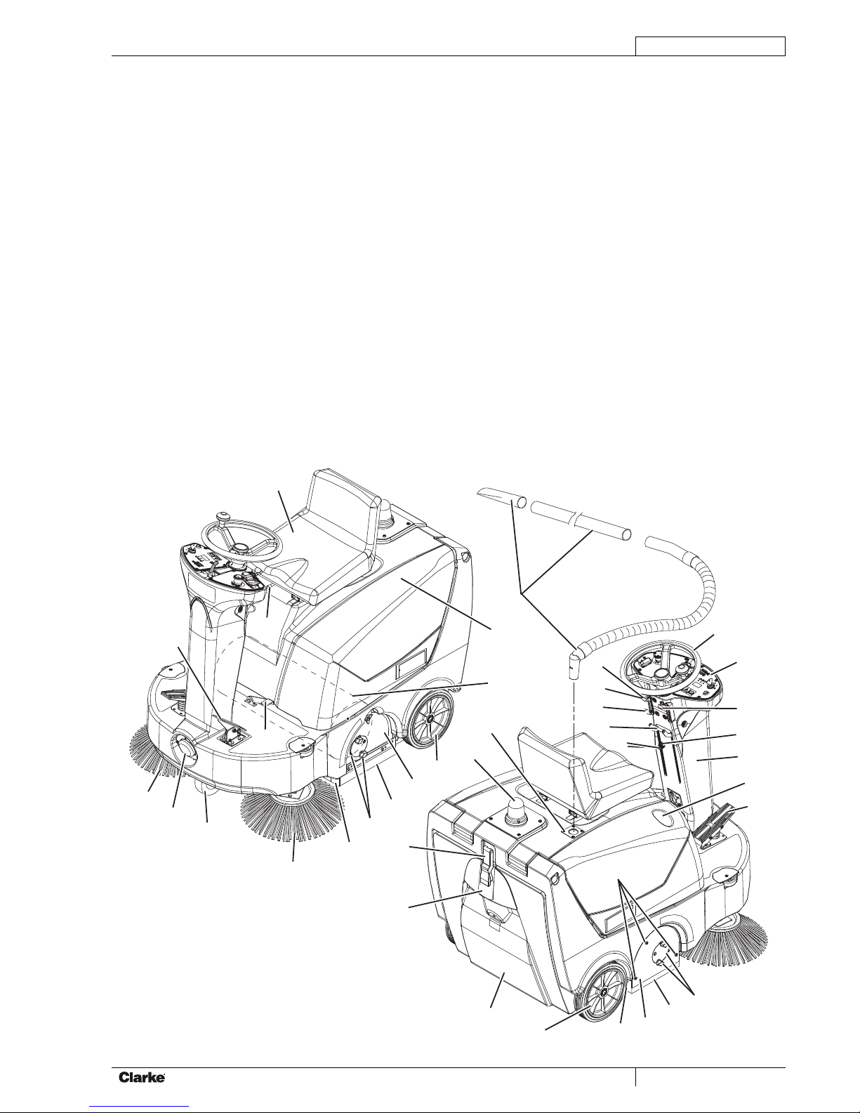
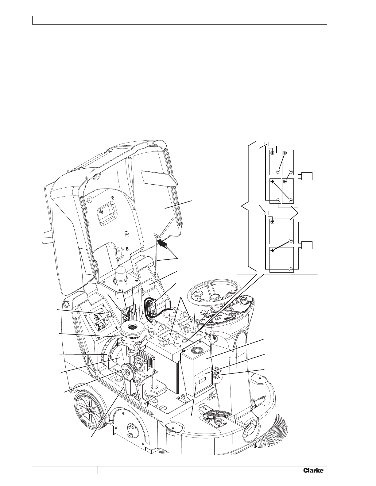
MACHINE DESCRIPTION .......................................................................................................................................... 5
MACHINE STRUCTURE ............................................................................................................................................................5
CONTROL PANEL......................................................................................................................................................................7
ACCESSORIES/OPTIONS........................................................................................................................................................7
TECHNICAL DATA......................................................................................................................................................................8
WIRING DIAGRAM.....................................................................................................................................................................9
USE ........................................................................................................................................................................... 10
BATTERY CHECK/SETTING ON A NEW MACHINE...............................................................................................................10
WET OR GEL BATTERY SETTING..........................................................................................................................................11
BEFORE START-UP.................................................................................................................................................................11
MACHINE START AND STOP..................................................................................................................................................12
PARKING BRAKE.....................................................................................................................................................................12
MACHINE OPERATION ...........................................................................................................................................................13
HOPPER EMPTYING...............................................................................................................................................................13
AFTER USING THE MACHINE................................................................................................................................................13
PUSHING/TOWING THE MACHINE........................................................................................................................................13
MACHINE LONG INACTIVITY .................................................................................................................................................13
FIRST PERIOD OF USE ..........................................................................................................................................................13
MAINTENANCE........................................................................................................................................................ 14
SCHEDULED MAINTENANCE TABLE ....................................................................................................................................14
MAIN BROOM HEIGHT CHECK AND ADJUSTMENT.............................................................................................................15
MAIN BROOM REPLACEMENT ..............................................................................................................................................16
SIDE BROOM HEIGHT CHECK AND ADJUSTMENT .............................................................................................................17
SIDE BROOM REPLACEMENT...............................................................................................................................................17
DUST FILTER CLEANING AND INTEGRITY CHECK .............................................................................................................18
SKIRT HEIGHT AND OPERATION CHECK.............................................................................................................................19
HOOD SAFETY SWITCH OPERATION CHECK .....................................................................................................................20
BATTERY CHARGING .............................................................................................................................................................21
FUSE CHECK/REPLACEMENT/RESET..................................................................................................................................22
SAFETY FUNCTIONS .............................................................................................................................................. 23
EMERGENCY PUSH-BUTTON................................................................................................................................................23
HOOD SAFETY SWITCH.........................................................................................................................................................23
DRIVER SEAT MICROSWITCH...............................................................................................................................................23
TROUBLESHOOTING.............................................................................................................................................. 23
SCRAPPING ............................................................................................................................................................. 24
PART LIST ................................................................................................................................................................ 73

ENGLISH
2Operator’s Manual - RSW 37
INTRODUCTION
NOTE
The numbers in brackets refer to the components shown in Machine Description chapter.
MANUAL PURPOSE AND CONTENTS
The purpose of this Manual is to provide the operator with all necessary information to use the machine properly in a safe and
autonomous way.
It contains information about technical data, safety, operation, storage, maintenance, spare parts and disposal.
Before performing any procedure on the machine, the operators and qualified technicians must read this Manual carefully.
Contact Clarke in case of doubts regarding the interpretation of the instructions and for any further information.
TARGET
This Manual is intended for operators and technicians qualified to perform the machine maintenance.
The operators must not perform procedures reserved for qualified technicians. Clarke will not be responsible for damages
coming from failure to follow these instructions.
HOW TO KEEP THIS MANUAL
The Operator’s Manual must be kept near the machine, inside an adequate case, away from liquids and other substances that
can cause damage to it.
IDENTIFICATION DATA
The machine model and serial number are marked on the plate (41) applied on the frame and can be read by opening the
machine hood (10).
The machine production year is indicated by the first two figures of the machine serial number.
This information is useful when requiring machine spare parts. Use the following table to write down the machine identification
data.
MACHINE model ...............................................................................
MACHINE serial number ...................................................................
OTHER REFERENCE MANUALS
Electronic Battery Charger Manual, to be considered an integral part of this Manual–
Moreover, the following Manuals are available:
Service Manual (that can be consulted at any Clarke Service Center)–
SPARE PARTS AND MAINTENANCE
All necessary operating, maintenance and repair procedures must be carried out by qualified personnel or by Clarke Service
Centers listed at the end of this Manual. Only original spare parts and accessories must be used.
Call Clarke for service or to order spare parts and accessories, specifying the machine model and serial number.
CHANGES AND IMPROVEMENTS
Clarke constantly improves its products and reserves the right to make changes and improvements at its discretion without
being obliged to apply such benefits to the machines that were previously sold.
Any change and/or addition of accessory must be approved and performed by Clarke.
OPERATION CAPABILITIES
This sweeper has been designed and built to clean (by sweeping and vacuuming) smooth and solid floors, in civil and industrial
environments and to collect dust and light debris under safe operation conditions by a qualified operator.
CONVENTIONS
Forward, backward, front, rear, left or right are intended with reference to the operator’s position, that is to say on the driver’s
seat, with the hands on the steering wheel (1).

ENGLISH
Operator’s Manual - RSW 37 3
UNPACKING/DELIVERY
When the machine is delivered, check that the packing and the machine were not damaged during transportation. In case of
visible damages, keep the packing and have it checked by the carrier that delivered it. Call the Carrier immediately to fill in a
damage claim.
Check that the machine is equipped with the following features:
Technical documents:–
Sweeper User Manual and Spare Parts List•
Electronic battery charger Manual•
SAFETY
The following symbols indicate potentially dangerous situations. Always read this information carefully and take all necessary
precautions to safeguard people and property.
The operator’s cooperation is essential in order to prevent injury. No accident prevention program is effective without the total
cooperation of the person responsible for the machine operation. Most of the accidents that may occur in a factory, while
working or moving around, are caused by failure to comply with the simplest rules for exercising prudence. A careful and prudent
operator is the best guarantee against accidents and is essential for successful completion of any prevention program.
SYMBOLS
DANGER!
It indicates a dangerous situation with risk of death for the operator.
WARNING!
It indicates a potential risk of injury for people.
CAUTION!
It indicates a caution or a remark related to important or useful functions. Pay particular attention to the
paragraphs marked by this symbol.
NOTE
It indicates a remark related to important or useful functions.
CONSULTATION
It indicates the necessity to refer to the Operator’s Manual before performing any procedure.
GENERAL INSTRUCTIONS
Specific warnings and cautions to inform about potential damages to people and machine are shown below.
DANGER!
Before performing any maintenance, repair, cleaning or replacement procedure remove the ignition key,–
engage the parking brake and disconnect the battery.
This machine must be used by properly trained operators only. Children or disabled people cannot use–
this machine.
Sharp turns must be made at slowest possible speed. Avoid abrupt turns on incline.–
Do not operate the machine near toxic, dangerous, flammable and/or explosive powders, liquids or–
vapors: This machine is not suitable for collecting dangerous powders.
Do not wear jewelry when working near electrical components.–
Do not work under the lifted machine without supporting it with safety stands.–
When working under the open hood, ensure that it cannot be closed by accident.–
Keep the battery away from sparks, flames and incandescent material. During normal operation,–
explosive gases are released.
If the machine is equipped with lead (WET) batteries, battery charging produces highly explosive–
hydrogen gas. Keep the hood open when charging the batteries and perform this procedure in well-
ventilated areas and away from naked flames.
When lead (WET) batteries are installed on the machine, do not tilt the machine more than 30° from the–
horizontal plane to prevent the highly corrosive acid from leaking out of the batteries. When the machine
is to be tilted to perform maintenance procedures, remove the batteries.

ENGLISH
4Operator’s Manual - RSW 37
WARNING!
Carefully read all the instructions before performing any maintenance/repair procedure.–
Take all necessary precautions to prevent hair, jewelry and loose clothes from being caught by the–
machine moving parts.
Before using the battery charger, ensure that frequency and voltage values, indicated on the machine–
serial number plate, match the electrical mains voltage.
Do not pull or carry the machine by the battery charger cable and never use the battery charger cable–
as a handle. Do not close a door on the battery charger cable, or pull the battery charger cable around
sharp edges or corners. Do not run the machine on the battery charger cable.
Keep the battery charger cable away from heated surfaces.
Do not charge the batteries if the battery charger cable or the plug are damaged. If the battery charger–
cable is damaged, contact Clarke Service Center.
To reduce the risk of fire, electric shock, or injury, do not leave the machine unattended when it is–
plugged in. Before performing any maintenance procedure, disconnect the battery charger cable from
the electrical mains.
Do not smoke while charging the batteries.–
To avoid any unauthorized use of the machine, remove the ignition key.–
Do not leave the machine unattended without being sure that it cannot move independently.–
Do not use the machine on slopes with a gradient exceeding the specifications.–
Use only brooms supplied with the machine and those specified in the User Manual. Using other brooms–
could reduce safety.
Before using the machine, close all doors and/or covers.–
Do not use the machine in particularly dusty areas.–
Use the machine only where a proper lighting is provided.–
If the machine is to be used where there are other people besides the operator, it is necessary to install–
the pivoting light (optional).
Do not wash the machine with direct or pressurized water jets, or with corrosive substances. Do not use–
compressed air to clean this type of machine, except for the filters (see the relevant paragraph).
While using this machine, take care not to cause damage to other people, and children especially.–
Do not allow to be used as a toy. Close attention is necessary when used near children.–
Use only as shown in this Manual. Use only Clarke’s recommended accessories.–
Do not lean liquid containers on the machine, use the relevant can holder.–
The machine storage temperature must be 32°F to 104°F (0°C to +40°C).–
The machine operating temperature must be between 32°F and 104°F (0°C and +40°C).–
The humidity must be between 30% and 95%.–
Always protect the machine against the sun, rain and bad weather, both under operation and inactivity–
condition. Store the machine indoors, in a dry place: This machine must be used in dry conditions, it
must not be used or kept outdoors in wet conditions.
Do not use the machine as a means of transport, or for pushing/towing.–
Do not allow the brushes to operate while the machine is stationary to avoid damaging the floor.–
In case of fire, use a powder fire extinguisher, not a water one.–
Do not bump into shelves or scaffoldings, especially where there is a risk of falling objects.–
Adjust the operation speed to suit the floor conditions.–
Avoid sudden stops when the machine is going downhill. Avoid sharp turns. Drive at slow speed when–
going downhill.
This machine cannot be used on roads or public streets.–
Do not tamper with the machine safety guards.–
Follow the routine maintenance procedures scrupulously.–
Do not remove or modify the plates affixed to the machine.–
In case of machine malfunctions, ensure that these are not caused by a lack of maintenance. Otherwise,–
request assistance from the authorized personnel or from an authorized Service Center.
If parts must be replaced, require ORIGINAL spare parts from an authorized Dealer or Retailer.–
To ensure machine proper and safe operation, the scheduled maintenance shown in the relevant chapter–
of this Manual must be performed by the authorized personnel or by an authorized Service Center.
The machine must be disposed of properly, because of the presence of toxic-harmful materials–
(batteries, oil, plastics, etc.), which are subject to standards that require disposal in special centres (see
Scrapping chapter).

ENGLISH
Operator’s Manual - RSW 37 5
MACHINE DESCRIPTION
MACHINE STRUCTURE
Steering wheel1.
Control panel2.
Vacuum activation/deactivation lever3.
Side broom lifting/lowering lever4.
Forward/reverse gear pedal5.
Service brake pedal6.
Parking brake lever (it acts on the front wheel)7.
The parking brake is engaged7a.
The parking brake is disengaged7b.
Front skirt lifting pedal8.
Can holder9.
Hood10.
Rear wheels on fixed axle11.
Front driving and steering wheel12.
Right side broom13.
Left side broom14.
Main broom15.
Left side skirt16.
Right side skirt17.
Front skirt18.
Rear skirt19.
Hopper20.
Hopper hook21.
Debris container handle22.
Main broom left lid23.
Main broom height left adjusting knob24.
Main broom height right adjusting knob25.
Main broom right lid26.
Main broom right lid mounting screws27.
Pivoting light (always on when the ignition key is turned28.
to “I”) (optional)
Driver’s seat with safety microswitch29.
Additional hole for manual vacuum system kit (optional)30.
Adjustable steering column31.
Working light (optional)32.
Side broom height adjusting knob33.
Seat longitudinal position adjusting lever34.
Manual vacuum system (optional)35.
Side broom height adjusting knob ring nut36.
28
30
35
10
15
11
23
16
24
29
18
14
12
32
13
34
8
6
21
22
27
25
17
26
19
11
20
7b
7a
2
4
33
3
1
31
9
5
36
7
S311291C

ENGLISH
6Operator’s Manual - RSW 37
MACHINE NOMENCLATURE (Continues)
Serial number plate/technical data/EC certification41.
Hood (open)42.
Hood support rod43.
Batteries44.
Battery caps (for WET batteries)45.
Battery connector46.
Electronic battery charger47.
Battery charger-electrical mains connecting cable48.
Lamellar fuse box (accessories)49.
Main broom/vacuum fan motor circuit breaker50.
Drive system circuit breaker51.
Lead (WET) or gel (GEL) battery selector on the52.
electronic battery charger
Charged battery warning light (green)53.
Main broom belt54.
Main broom drive pulley55.
Vacuum fan56.
Main motor57.
Manual vacuum system (optional)58.
Switch for machine pushing59.
Battery connection diagrams60.
6V 6V
6V 6V
12V
12V
17
17
16
60 16
14
42
43
41
46
44
48
53
47
45
51
50 49
59
58
56
57
55
54
52
S311292C

ENGLISH
Operator’s Manual - RSW 37 7
CONTROL PANEL
Left control panel71.
Ignition key:72.
When turned to “O”, it turns the electrical system off•
and disables all machine functions.
When turned to “I” it enables the machines functions.•
When turned to “II” it starts the main motor.•
As soon as the main motor starts, release the key,
which returns to “I”.
Discharged battery warning light (red). When it is on, the73.
autonomy is over, the batteries must be recharged (see
the procedure in the relevant paragraph).
Semi-discharged battery warning light (yellow). When it74.
is on, the residual autonomy is few minutes.
Charged battery warning light (green). When it is on,75.
the residual autonomy depends on battery capacity and
working conditions.
Display. When pressed, it shows in sequence:76.
Working hours•
Last digit of the hours - (dot) - minutes•
Battery voltage (V)•
Display selection push-button: hour counter/hour and77.
minute counter/battery voltage (V)
Horn78.
Switch having the following functions:79.
in the central position: off•
forward: it turns on the main broom and the vacuum•
fan
backward: it turns on the filter shaker•
Manual vacuum system additional hole switch (optional)80.
Working light switch (optional)81.
Emergency push-button Press it in case of emergency82.
to stop all the machine functions. To deactivate the
emergency push-button, turn it in the direction shown by
the arrow.
Panel fastening screws83.
Right control panel84.
Steering column tilting adjusting lever85.
82
71 84
73
74
75
72
78
76
77
83
81
80
79
85
S311289C
ACCESSORIES/OPTIONS
In addition to the standard components, the machine can be equipped with the following accessories/options, according to the
machine specific use:
GEL batteries–
Main and side brooms with harder or softer bristles–
Antistatic polyester or polyester BIA C dust filter–
Manual vacuum system–
Working light–
Pivoting light–
Skirts of various materials–

ENGLISH
8Operator’s Manual - RSW 37
TECHNICAL DATA
General Values
Machine Length 49.40 in (1,255 mm)
Machine width (without side brooms) 31.30 in (795 mm)
Machine height 45.47 in (1,155 mm)
Cleaning width (with side brooms) 39.37 in (1,000 mm)
Cleaning width (without side brooms) 23.62 in (600 mm)
Minimum distance from the floor (skirts not included) 1.57 in (40 mm)
Main broom size (diameter x length) 10.43 x 23.62 in (265 x 600 mm)
Side broom diameter 16.53 in (420 mm)
Front steering and driving wheel (diameter x width) 7.87 in x 1.97 in (200 mm x 50 mm)
Rear wheel (diameter x length) 9.84 in x 1.97 in (250 x 50 mm)
Front wheel specific pressure on the floor 130.5 psi (0.9 N/mm2)
Rear wheel specific pressure on the floor 116 psi (0.8 N/mm2)
Total machine weight (without batteries) 65.27 lb (143.89 kg)
Hopper capacity 1.41 ft3(40 liters)
Main broom and vacuum fan motor 0.8 HP (600 W)
Side broom motors 0.08 HP (60 W)
Drive system motor 0.53 HP (400 W)
Filter shaker motor 0.01 HP (12 W)
Sound pressure level at workstation (ISO 11201, ISO 4871) (LpA) 71.6 ± 3 dB(A)
Machine sound pressure level (ISO 3744, ISO 4871) (LwA) 89 dB(A)
Vibration level at the operator’s arms (ISO 5349-1) (*) < 98,4 in/s2(< 2,5m/s2)
Vibration level at the operator’s body (ISO 2631-1) (*) < 19,68 in/s2(< 0,5m/s2)
Under normal working conditions, on a level asphalt surface.(*)
Performance Values
Maximum forward speed 8.85 mph (5.5 km/h)
Maximum reverse speed 7.1 mph (4.4 km/h)
Maximum gradient when working 1,14° (2%)
Gradeability 9° (16%)
Minimum turning radius 38.70 in (983 mm)
Batteries Values
Battery voltage 24 V
Standard battery Lead with acid electrolyte (WET)
Optional battery Gel, hermetic (GEL)
Battery capacity 100 – 240 Ah C5
Battery compartment maximum size 14.05 x 14.76 x 15.16 in (357 x 375 x 385 mm)
Dust vacuuming and filtering Values
Paper dust filter 5-10 μm 32.3 ft2(3 m2)
Main broom compartment vacuum 0.026 psi (18.3 mmH2O)

ENGLISH
Operator’s Manual - RSW 37 9
WIRING DIAGRAM
Key
BAT Batteries
BE1 Pivoting light
BZ1 Reverse gear buzzer
C1 Battery connector
CH1 Battery charger
EB1 Hour counter and battery voltage display
EB2 Drive system electronic board
ES0 Starting relay
ES1 Main broom switch
ES2 Filter shaker relay
ES3 Manual vacuum system switch
FA Main broom/vacuum fan fuse
FL Drive system electronic board fuse (3 A)
FT Drive system fuse
F1 Main fuse (ignition key circuit) (25 A)
F2 Filter shaker motor fuse (25 A)
F3 Manual vacuum system fuse (40 A) (optional)
F4 Horn and pivoting light fuse (10 A) (optional)
F5 Working light fuse (10 A) (optional)
F6 Side broom motor fuse (10 A)
HN1 Horn
K1 Ignition key
L1 Working light (optional)
M1 Main broom motor
M2 Drive system motor
M3 Filter shaker motor
M4 Right side broom motor
M5 Left side broom motor
M6 Manual vacuum system motor (optional)
P1 Horn switch
R1 Drive speed potentiometer
SWC Hood safety switch
SWS Emergency push-button
SW1 Main broom, vacuum fan and filter shaker switch
SW2 Driver’s seat safety microswitch
SW3 Forward/reverse gear microswitch
SW4 Side broom microswitch
SW5 Drive system switch
SW6 Manual vacuum system switch (optional)
SW7 Working light switch
Color code
BK Black
BU Blue
BN Brown
GN Green
GY Gray
OG Orange
PK Pink
RD Red
VT Violet
WH White
YE Yellow
-
+
-
+
R
R
BAT CH
RD
BK
C1
C1
VTBK
BK
M1
BK
BK
85
BK
ES2
VT
ES0
86
SW1
HN1
ES1
WH
RD
FA
ES0
WH
30
P1
PK
87
F1
F4
K1
50 15
30
RD
SWS
BU
PK
BK
BE1
SW7
GY
ES3
SW6
ES1
inst.
stab.
EB1
BK
L1
GY
F5
BK
M4
BK
M5
SW5
F6
EB2
M1 M2 B+
B-
FT
BK
M2
BK
M3
ES2
VT
F2
R1
SW2
BK
M6
ES3
BN
F3
BZ1
BU
RD RD
WH
OG
OG
BUBK BN
WHRD
RD
BU
RD
RD
VT BN
RD RD RD
465
132
BK
WH
BK YE
WH RD
RD
BK
BU
RD BU
OG
BKRD
30
87
J1
J2
SW4
RD
WH
(*) If the machine have not the
optional charger (CH) installed, C2
connectors are connected togheter.
FL
WH
C2(*) C2(*)
SWC
BU
S311290C

ENGLISH
10 Operator’s Manual - RSW 37
USE
WARNING!
On some points of the machine there are some adhesive plates indicating:
DANGER–
WARNING–
CAUTION–
NOTE–
While reading this Manual, the operator must pay particular attention to the symbols shown on the plates.
Do not cover these plates for any reason and immediately replace them if damaged.
BATTERY CHECK/SETTING ON A NEW MACHINE
WARNING!
If the machine must be pushed for service reasons (missing batteries, discharged batteries, etc.) do not
exceed 2.5 mph (4 km/h).
NOTE
The electronic battery charger must be connected to the batteries to allow the machine to operate.
The machine requires two 12 V batteries or four 6 V batteries connected according to the diagrams (60).
The machine can be supplied in one of the following modes:
Batteries (WET or GEL) already installed and chargeda)
Batteries (WET) installed on the machine, but without electrolyteb)
Without batteriesc)
According to machine configuration, proceed as follows.
Batteries (WET or GEL) already installed and chargeda)
Open the machine hood (10) and fasten it with the support rod (43), then check that the batteries are connected to the1.
machine with the connector (46).
Disengage the support rod and close the hood (42). Check that the hood (10) is properly closed.2.
Insert the ignition key (72) and turn it to “II” (without pressing the pedal (5)), then release it. If the green warning light3.
(75) turns on, the batteries are charged. If the yellow (74) or red (73) warning light turns on, the batteries must be
charged (see the procedure in Maintenance chapter).
Batteries (WET) installed on the machine, but without electrolyteb)
Open the machine hood (10) and engage the hood support rod (43).1.
Remove all battery caps (45).2.
WARNING!
Pay attention when using sulfuric acid, as it is corrosive. If it comes in contact with skin or eyes, rinse
thoroughly with water and call a physician.
Batteries have to be filled in a well-ventilated area.
Use protective gloves.
Fill the battery cells with sulfuric acid for batteries (density 2.79 to 2.84 lb at 77°F (1.27 to 1.29 kg at 25°C)) according3.
to the instructions shown in the Battery Manual. The correct quantity of sulfuric acid is shown in the Battery Manual.
Let the batteries rest and fill in with sulfuric acid according to the instructions shown in the Battery Manual.4.
Charge the batteries (see the procedure in the Maintenance chapter).5.
Without batteriesc)
Buy appropriate batteries (see the Technical Data chapter). For battery choice and installation, apply to qualified1.
battery Retailers.
Install the batteries according to the diagrams (60).2.
Set the machine and the battery charger according to the type of batteries installed, as shown in the next paragraph.3.

ENGLISH
Operator’s Manual - RSW 37 11
WET OR GEL BATTERY SETTING
According to the type of batteries (WET or GEL), set the machine electronic board and the battery charger, according to the
following procedure:
Turn the ignition key (72) to “0”.1.
Open the hood (42) and engage the hood support rod (43).2.
Machine setting
The machine factory setting is for lead (WET) batteries. If this setting corresponds to the type of batteries installed on the3.
machine, go to the next paragraph, otherwise perform the following procedures:
Disconnect the battery connector (45).•
Remove the screws (83) and carefully remove the right control panel (84).•
Remove the jumper wire (A, Fig. 1) from WET connectors (B) for lead batteries, and connect it to GEL connectors (C)•
for gel batteries.
Carefully install the control panel (84) and the relevant screws.•
Reconnect the battery connector (46).•
B
C
A
S310201C
Figure 1
Battery charger setting
Turn the selector (52) to WET or GEL according to the type of batteries.4.
Charge the batteries (see the procedure in the Maintenance chapter).5.
BEFORE START-UP
CAUTION!
Make sure that there are no open doors/hoods and that the machine is in normal operating conditions.
Make sure that the hopper (20) is properly closed.
If the machine has not been used after being transported, check that all the blocks used for the
transportation have been removed.

ENGLISH
12 Operator’s Manual - RSW 37
MACHINE START AND STOP
Starting the machine
Sit on the driver’s seat (29) and, if it is necessary for an easier access to the machine, push the lever (85) and tilt the1.
steering column (31) forward.
Push the lever (85) forward and tilt the steering column (31) forward or backward, to reach a comfortable position. Then2.
release the lever (85) and lock the steering column.
Turn the ignition key (72) to “II” and do not press the pedal (5), then release it; it will go back to “I”. Check that the green3.
warning light (75) turns on (charged battery). If the yellow or red warning light (73 or 74) turns on, turn the ignition key back
to “0” and charge the batteries (see the procedure in Maintenance chapter).
Disengage the parking brake.4.
Drive the machine to the working area, by keeping the hands on the steering wheel and pressing the pedal (5) on the front5.
side to move forward and on the rear side to move backward. The drive speed can be adjusted from zero to maximum
speed by increasing the pressure on the pedal (5).
NOTE
The driver’s seat (29) is equipped with a safety sensor, which allows the machine to be moved with the pedal (5) only
when the operator is on the driver’s seat.
Turn on the main broom and the vacuum fan by pressing the switch (79) forward.6.
Turn on the vacuum system by lowering the lever (3).7.
Lower the side brooms (13 and 14) by lowering the lever (4).8.
NOTE
The side brooms (13 and 14) can be lowered and lifted even when the machine is moving. The side brooms do not
turn when lifted, they turn only when lowered.
Start sweeping by turning the steering wheel (1) and moving the machine forward by pressing the pedal (5).9.
Stopping the machine
To stop the machine release the pedal (5).1.
To stop the machine quickly, also press the service brake pedal (6).
In case of emergency, press the emergency push-button (82) to immediately stop the machine. To deactivate the
emergency push-button (82), turn it clockwise.
Lift the side brooms (13 and 14) with the lever (4).2.
To turn off the main broom and the vacuum fan, turn the switch (79) to “0” (central) position.3.
To stop the machine, turn the ignition key (72) to “0”.4.
PARKING BRAKE
Engage the parking brake according to the following procedure:1.
Press the pedal (6) as necessary, then engage the brake by turning the lever (7) from (7b) position to (7a) position.•
Release the pedal (6).•
Disengage the parking brake according to the following procedure:2.
Press the pedal (6) and turn the lever (7) from (7a) position to (7b) position.•
Release the pedal (6).•
WARNING!
Before performing any maintenance, repair, cleaning or replacement procedure engage the parking brake.
Engage the parking brake when parking the machine on a slope or incline.

ENGLISH
Operator’s Manual - RSW 37 13
MACHINE OPERATION
WARNING!
Pay careful attention when operating the machine at high speed: sudden steering could cause this three-
wheel machine to become unstable due to weight distribution.
Always reduce the speed before steering.
Avoid stopping for a long time with the machine in the same position and the brooms rotating: this could create unwanted1.
marks on the floor.
To collect light and bulky waste materials, lift the front skirt by pressing the pedal (8); take into consideration that the2.
machine vacuum capability is reduced when the front skirt is lifted.
WARNING!
When operating on wet grounds, it is essential to turn off the vacuum system with the lever (3) to prevent the
dust filter from being damaged.
For machine proper operation, the dust filter must be as clean as possible. To keep the dust filter clean while sweeping,3.
turn off the vacuum system with the lever (3), then press the switch (79) for a while.
During this procedure the main motor and the vacuum fan are automatically stopped.
After cleaning the filter, press the switch (79) forward to turn on the main broom and the vacuum system, then start
sweeping again.
While working, repeat the procedure every 10 minutes on average (depending on the dustiness of the area to be cleaned).
NOTE
When the dust filter is clogged and/or the hopper is full, the machine cannot collect dust and debris anymore.
The hopper (20) should be emptied after each working cycle and whenever it is full (see the procedure in the following4.
paragraph).
HOPPER EMPTYING
Stop the machine by releasing the drive pedal.1.
Turn the ignition key (72) to “0”.2.
Engage the parking brake.3.
Disengage the hook (21) by pulling its lower end.4.
Remove the hopper (20) by using the handle (22), and dump it into special containers.5.
Reinsert the hopper and fasten it with the hook (21).6.
The machine is ready to start working again.7.
AFTER USING THE MACHINE
After working, before leaving the machine:
Lift the side brooms with the lever (4).–
Turn on the filter shaker with the switch (79).–
Empty the hopper (20) (see the procedure in the previous paragraph).–
Remove the ignition key (72).–
Engage the parking brake.–
PUSHING/TOWING THE MACHINE
To easily push/tow the machine when it is off, proceed as follows:
Open the hood (10).–
Turn the switch (59) to “0” and close the hood (10).–
Push or tow the machine.–
After pushing/towing the machine, turn the switch (59) to “I”.–
MACHINE LONG INACTIVITY
If the machine is not going to be used for more than 30 days, proceed as follows:
Check that the machine storage area is dry and clean.–
Disconnect the battery connector (46).–
Slightly lift the machine so that the skirts, the main broom and the wheels do not touch the ground.–
Disconnect the positive terminal (+) directly from the (+) pole of the batteries.–
FIRST PERIOD OF USE
After the first period of use (first 8 hours) it is necessary to carry out the following operations:
Check the machine fastening and connecting parts for proper tightening.1.
Check the visible parts for integrity and leakage.2.

ENGLISH
14 Operator’s Manual - RSW 37
MAINTENANCE
The lifespan of the machine and its maximum operating safety are ensured by correct and regular maintenance.
Provided below is the Scheduled Maintenance Table. The intervals shown may vary according to particular working conditions,
which are to be defined by the person in charge of the maintenance.
All scheduled or extraordinary maintenance procedures must be performed by qualified personnel, or by an authorized Service
Center.
This Manual describes only the easiest and most common maintenance procedures.
For other maintenance procedures contained in the Scheduled Maintenance Table or for extraordinary maintenance procedures
see the specific Service Manual that can be consulted at any Service Center.
WARNING!
To perform maintenance procedures, the machine must be off, the ignition key removed, and, if necessary,
the batteries must be disconnected.
Read carefully the instructions in Safety chapter before performing any maintenance procedure.
SCHEDULED MAINTENANCE TABLE
Procedure Upon delivery
Every
10
hours
Every
50
hours
Every
100
hours
Every
200
hours
Every
400
hours
WET battery fluid level check
Side and main broom height check and adjustment
Dust filter cleaning and integrity check
Skirt height and operation check
Filter shaker operation check (*)
Hood safety switch operation check (*)
Main broom driving belt visual inspection (*)
Nut and screw tightening check (*) (1)
Service and parking brake check and adjustment (*)
Main broom driving belt replacement (*)
Main motor and drive system motor carbon brush check or replacement (*)
For the relevant procedure, see the Service Manual.(*)
And after the first 8 running-in hours.(1)

ENGLISH
Operator’s Manual - RSW 37 15
NOTE
Brooms of various hardness are available. This
procedure is applicable to all types of brooms.
Check the main broom distance from the floor as shown1.
below:
Drive the machine on a level floor.•
Keep the machine stationary and turn on the main•
broom for a few seconds.
Stop and lift the main broom, then move the machine.•
Check that the main broom print (A, Fig. 2), along its•
length, is 0.8 to 1.6 in (20 to 40 mm) wide.
If the print (A) is not within specifications, adjust the•
broom height as shown in step 2.
Drive the machine on a level ground and engage the2.
parking brake.
Turn the ignition switch (72) to “0”.3.
Loosen the knobs (A, Fig. 3) on both sides of the4.
machine.
On both sides of the machine, loosen the knobs (A)5.
and move the broom height variation indicator (B) as
necessary, then tighten the knobs (S).
The indicator (B) must be in the same position on both6.
sides of the machine; the maximum difference allowed to
obtain the print (A, Fig. 2) shown in step 1 (0.8 – 1.6 in
(20 – 40 mm) wide) is two notches.
Perform step 1 again to check the proper adjustment of7.
the main broom height.
When the broom is too worn to be adjusted, replace it as8.
shown in the next paragraph.
CAUTION!
If the main broom print is excessive (larger than
1.6 in (40 mm)), the machine regular operation
is affected and the moving or electrical parts
can overheat, thus reducing machine life.
Pay careful attention when performing the
above-mentioned checks, and always use the
machine according to the indicated conditions.
0,8 - 1,6 in
A
S310027C
Figure 2
B
C
A
S310028C
Figure 3
MAIN BROOM HEIGHT CHECK AND ADJUSTMENT

ENGLISH
16 Operator’s Manual - RSW 37
MAIN BROOM REPLACEMENT
NOTE
Brooms of various hardness are available. This
procedure is applicable to all types of brooms.
CAUTION!
It is advisable to wear protective gloves when
replacing the side brooms because there can
be sharp debris between the bristles.
Drive the machine on a level ground and engage the1.
parking brake.
Turn the ignition switch (72) to “0”.2.
Loosen the knobs (A, Fig. 4) on both sides of the3.
machine.
Move the height variation indicators (B) until the broom4.
is at the maximum distance from the ground. Tighten the
knobs (A).
On the left side of the machine, loosen the knob (C).5.
Remove the broom door (A, Fig. 5) by pulling it upwards6.
to disengage the fasteners (B).
Remove the broom (C).7.
Check that the drive hub (A, Fig. 6) is free from dirt or8.
foreign materials (ropes, rags, etc.) accidentally rolled
up.
The new main broom must be installed with the bristles9.
rows (B) bent as shown in the figure.
Install the new broom (C) and ensure that the mesh (D)10.
correctly fits into the relevant drive hub (A).
Install the broom door (A, Fig. 5) by engaging the11.
fasteners (B).
Tighten the knob (C, Fig. 4).12.
Check and adjust the main broom height as shown in the13.
previous paragraph.
B
C
A
S310028C
Figure 4
S310029C
Figure 5
S310032C
Figure 6

ENGLISH
Operator’s Manual - RSW 37 17
SIDE BROOM HEIGHT CHECK AND ADJUSTMENT
NOTE
Brooms of various hardness are available. This
procedure is applicable to all types of brooms.
Check the side broom distance from the floor, according1.
to the following procedure:
Drive the machine on a level floor and lower the side•
brooms.
Keep the machine stationary, lower the side brooms•
and turn them on for a few seconds.
Stop and lift the side brooms, then move the machine•
and turn it off.
Check that the side broom prints are as shown in the•
figure (A and B, Fig. 7).
If the print is not within specifications, adjust the broom
height, according to the procedure shown in step 2.
Unlock the ring nut (36) by turning it counterclockwise,2.
then turn the knob (33) as necessary, clockwise or
counterclockwise, to adjust the broom height; then lock
the knob (33) with the ring nut (36).
Perform step 1 again to check the proper adjustment of3.
the side broom height.
When the brooms are too worn to be adjusted, replace4.
them as shown in the next paragraph.
SIDE BROOM REPLACEMENT
NOTE
Brooms of various hardness are available. This
procedure is applicable to all types of brooms.
CAUTION!
It is advisable to wear protective gloves when
replacing the side brooms because there can
be sharp debris between the bristles.
Drive the machine on a level ground and engage the1.
parking brake.
Turn the ignition switch (72) to “0” position.2.
Remove the screw (A, Fig. 8) inside the side broom, then3.
remove the broom and the hub (B) by disengaging it from
the shaft (C). Recover the key (D) and the washer (E).
At the workbench, remove the two screws and nuts (F)4.
and separate the broom (H) from the hub (G).
Install the new broom (H) on the hub (G) and tighten the5.
screws and the nuts (F).
Reinstall the new broom and the hub (B) on the machine6.
after seating the key (D). Reinstall the washer (E) and
tighten the screw (A).
Carry out the side broom height check and adjustment as7.
described in the previous paragraph.
A
B
S310199C
Figure 7
AB
C
D
E
F
F
G
H
S310034C
Figure 8

ENGLISH
18 Operator’s Manual - RSW 37
DUST FILTER CLEANING AND INTEGRITY CHECK
NOTE
Besides the standard paper filter, polyester filters
are also available. The following procedure is
applicable to each type of filter.
Drive the machine on a level ground and engage the1.
parking brake.
Turn the ignition switch (72) to “0”.2.
Remove the hopper hook (21).3.
Remove the hopper (20) with the handle (22).4.
Turn the handle (A, Fig. 9) downwards (90°5.
approximately) and let the filter frame (B) turn outwards.
Remove the dust filter (C).6.
In an outdoor area, clean the filter by shaking it on a level7.
and clean surface, tapping the side (A, Fig. 10) opposite
to the wire gauze (B). Complete the cleaning procedure
by using compressed air (C) at maximum 6 Bar, blowing
only from the side protected by the wire gauze (2), at a
minimum distance of 11.8 in (30 cm).
According to the filter type, observe the following
cautions:
Paper filter (standard): Do not use water or•
detergents to clean it; the filter can be damaged.
Polyester filter (optional): To clean it, see the above-•
mentioned instructions. If necessary, for a better
cleaning, it is allowed to wash the filter with water
and non-lathering detergents. This provides better
quality cleaning but reduces the life of the filter,
which will have to be replaced more frequently. Using
inadequate detergents can damage the filter.
Check the filter body for tears.8.
If necessary, clean the filter compartment rubber gasket9.
(D, Fig. 9) along its perimeter and check it for integrity. If
necessary, replace it.
Assemble the components in the reverse order of10.
disassembly.
Assemble the components in the reverse order of11.
disassembly, and pay particular attention to the following:
Install the filter (A, Fig. 10) with the wire gauze (B)•
facing the vacuum fan (56).
A
B
D
C
S310200C
Figure 9
A
B
C
6 Bar
11,8 in
S310036C
Figure 10
Other manuals for RSW 37
1
Table of contents
Languages:
Other Clarke Blower manuals