manuals.online logo
Brands
  1. Home
  2. •
  3. Brands
  4. •
  5. Clarke
  6. •
  7. Water Pump
  8. •
  9. Clarke C10 Manual

Clarke C10 Manual

Application, Installation and Maintenance Instructions
Clarke Tapered Grid Couplings
Type C10, C31 and C35
Sizes C1040T thru C1080T
For Electric Motor Driven Fire Pumps
Page 1 of 10 C132205 Sept 07
How to Use This Manual
This manual provides detailed instructions on
applications, installation, lubrication, maintenance, parts
identification, and dimensional data. Use the table of
contents below to locate required information.
Table of Contents
Introduction Page 1
Application Guidelines Page 1
Lubrication Page 1
Installation & Alignment Instructions Page 3
Annual Maintenance, Re-lube & Disassembly Page 5
Installation & Alignment Data Page 5
Parts Identification & Parts Interchangeability Page 6
Dimensional Data Page 8
CAREFULLY FOLLOW THE INSTRUCTIONS IN
THIS MANUAL FOR OPTIMUM PERFORMANCE
AND TROUBLE FREE SERVICE.
INTRODUCTION
This manual applies to sizes C1040T thru C1080T Clarke
Tapered Grid Couplings. These couplings are designed to
operate in either the horizontal or vertical position without
modification. Refer to Page 6 for part interchangeability.
Couplings should be installed in accordance with the
Standard for Installation of Stationary Pumps for Fire
Protection, NFPA 20.
TYPE C10 TAPERED GRID COUPLING
APPLICATION GUIDELINES
Motor certified couplings (for rated BHP’s and speeds
given in table below) can only be used with Centrifugal
Fire Pumps (Service factor 1.0). Contact Clarke for
application guidelines for Positive Displacement Fire
Pumps (Service factors 1.5 to 2.25).
BHP = Torque (in.-lb) x RPM
63024
Couplings cannot be used with diesel engines.
T-hubs and shaft hubs are designed for clearance fit with
set screw over keyways.
Consult Clarke for oversize bores with shallow keyways.
It is recommended that a torsional analysis be conducted
on the actual drive system arrangement.
LUBRICATION
Adequate lubrication is essential for satisfactory
operation. Page 2 provides a list of typical lubricants and
specifications for general purpose and long term greases.
Because of its superior lubricating characteristics and low
centrifuge properties, Long Term Grease (LTG) provided
by Clarke is highly recommended. Sizes C1040T to
C1080T are furnished with a pre-measured amount of
grease for each coupling. The use of general purpose
grease requires re-lubrication of the coupling at least
annually.
Page 2 of 10
LONG TERM GREASE (LTG)
The high centrifugal forces encountered in couplings
separate the base oil and thickener of general purpose
greases. Heavy thickener, which has no lubrication
qualities, accumulates in the grid-groove area of tapered
grid couplings resulting in premature hub or grid failure
unless periodic lubrication cycles are maintained.
Long Term Grease (LTG) provided by Clarke was
developed specifically for couplings. It resists separation
of the oil and thickener. The consistency of LTG changes
with operating conditions. As manufactured it is an NLGI
#1/#2 grade. Working of the lubricant under actual
service conditions causes it to become semi-fluid while
the grease near the seals will set to a heavier grade,
helping to prevent leakage. LTG is highly resistant to
separation, easily out performing all other lubricants
tested. The resistance to separation allows the lubricant to
be used for relatively long periods of time. Tapered grid
couplings initially lubricated with LTG will not require
re-lubrication until the connected equipment is stopped
for servicing. If a coupling leaks grease, is exposed to
extreme temperatures, excessive moisture, or experiences
frequent reversals, more frequent lubrication is required.
Although LTG grease is compatible with most other
coupling greases, the mixing of greases may dilute the
benefits of LTG.
USDA Approval
LTG has the United States Department of Agriculture
Food Safety & Inspection Service approval for
applications where there is no possibility of contact with
edible products. (H-2 ratings).
CAUTION: Do not use LTG in bearings.
Specifications –LTG
The values shown are typical and slight variations are
permissible.
AMBIENT TEMPERATURE RANGE - -20°F (-29°C)
to 250°F (121°C). Min. Pump = 20°F (-7°C).
MINIMUM BASE OIL VISCOSITY –3300SSU
(715cST) @ 100°F (38°C).
THICKENER –Lithium & soap/polymer.
CENTRIFUGE SEPARATION CHARACTERISTICS –
ASTM #D4425 (Centrifuge Test) –K36 = 2/24 max.,
very high resistance to centrifuging.
NLGI GRADE (ASTM D-217) –½
CONSISTENCY (ASTM D-217) –60 stroke worked
penetration value in the range of 315 to 360 measured at
77°F (25°C)
MINIMUM DROPPING POINT - 350°F (177°C)
minimum
MINIMUM TIMKEN O.K. LOAD –40lbs.
ADDITIVES –Rust and oxidation inhibitors that do not
corrode steel or swell or deteriorate synthetic seals.
Packaging
14 oz. (0,4 kg) CARTIRIDGES –individual or case lots
of 10 or 30.
35 lb. (16 kg) PAIL, 120 lb. (54 kg) KEG & 400 lb. (181
kg) DRUMS.
General Purpose Grease
Annual Lubrication –The following specifications and
lubricants for general purpose grease apply to tapered grid
couplings that are lubricated annually and operate within
ambient temperatures of 0°F to 150°F (-18°C to 66°C).
For temperatures beyond this range (see Table 1), consult
the Factory. If a coupling leaks grease, is exposed to
extreme temperatures, excessive moisture or experiences
frequent reversals, more frequent lubrication may be
required.
Specifications –General Purpose Coupling Lubricants
The values shown are typical and slight variations are
permissible.
DROPPING POINT - 300°F (149°C) or higher.
CONSISTENCY –NLGI No. 2 with 60 stroke worked
penetration value in the range of 250 to 300.
SEPARATION AND RESISTANCE –Low oil
separation rate and high resistance to separation from
centrifuging.
LIQUID CONSTITUENT –Possess good lubricating
properties equivalent to a high quality, well refined
petroleum oil.
INACTIVE –Must not corrode steel or cause swelling or
deterioration of synthetic seals.
CLEAN –Free from foreign inclusions.
General Purpose Greases Meeting Clarke
Specifications
Lubricants listed below are typical products only and
should not be construed as exclusive recommendations.
Page 3 of 10
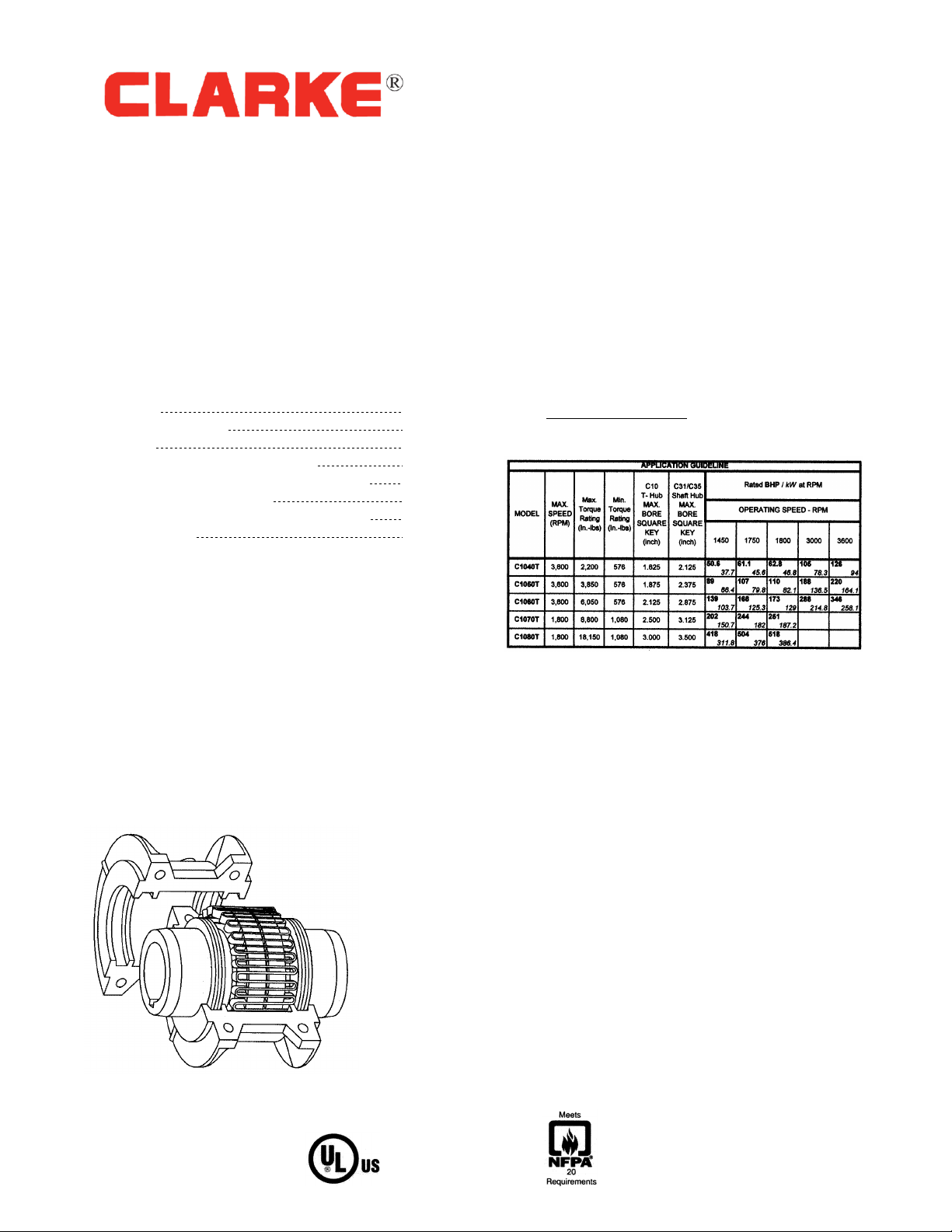
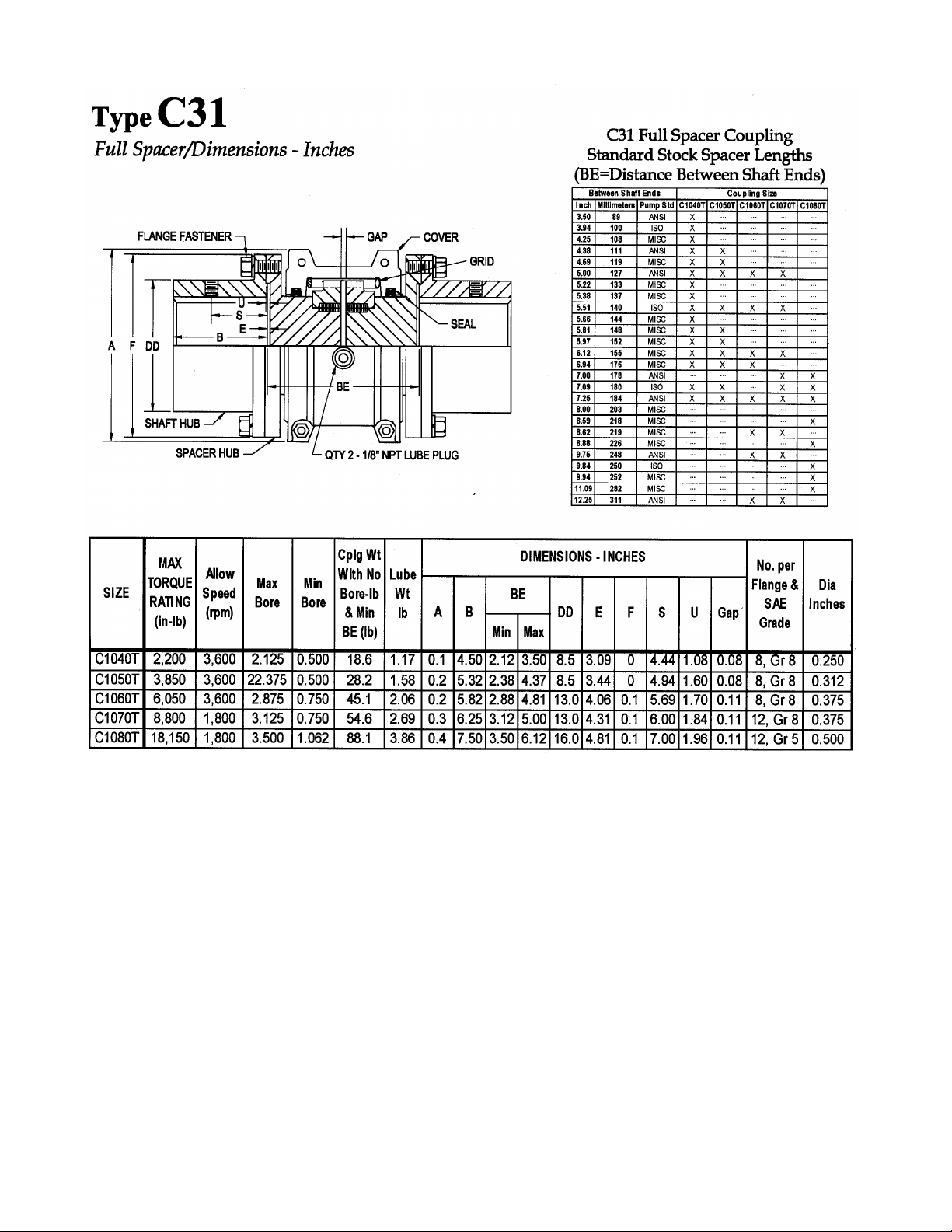
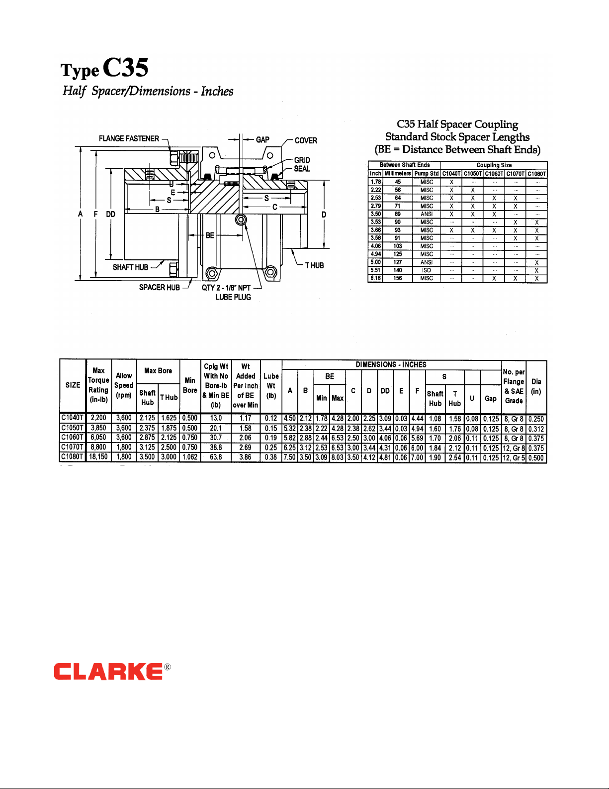
INSTALLATION AND ALIGNMENT OF TYPE C10,
C31 and C35 TAPERED GRID COUPLINGS
Installation
Only standard mechanics tools, wrenches, a straight edge
and feeler gauges are required to install Clarke tapered
grid couplings. Coupling Sizes C1040T thru C1080T are
generally furnished for CLEARANCE FIT with setscrew
over the keyway. Special applications may call for
Interference fit with or without a setscrew over the
keyway.
CLEARANCE FIT HUBS –Clean all parts using a non-
flammable solvent. Check hubs, shafts and keyways for
burrs. Do not heat clearance fit hubs. Install keys, mount
hubs with flange face flush with shaft ends or as
otherwise specified and tighten setscrews.
INTERFERENCE FIT HUBS –Furnished without
setscrews. Heat hubs to a maximum of 275°F (135°C)
using an oven, torch, induction heater or an oil bath. To
prevent seal damage, DO NOT heat hubs beyond a
maximum temperature of 400°F (205°C). When an oxy-
acetylene or blow torch is used, use an excess acetylene
mixture. Mark hubs near the center of their length in
several places on hub body with a temperature sensitive
crayon, 275°F (135°C) melt temperature. Direct flame
towards hub bore using constant motion to avoid
overheating an area.
WARNING: If an oil bath is used, the oil must have a
flash point of 350°F (177°C) or higher. Do not rest hubs
on the bottom of the container. Do not use an open flame
in a combustible atmosphere or near combustible
materials. Heat hubs as instructed above. Mount hubs as
quickly as possible with hub face flush with shaft end.
Allow hubs to cool before proceeding. Insert setscrews
(if required) and tighten.
Maximize Performance and Life
The performance and life of couplings depend largely
upon how you install and maintain them. Before
installing couplings, make certain that foundations of
equipment to be connected meet manufacturers’
requirements. Check for soft foot. The use of stainless
steel shims is recommended. Measuring misalignment
and positioning equipment within alignment tolerances is
simplified with an alignment computer. These
calculations can also be done graphically or
mathematically. Alignment is shown using spacer bar and
straight edge. This practice has proven to be adequate for
many industrial applications. However, for superior final
alignment, the use of dial indicators, lasers, alignment
computers or graphical analysis is recommended.
CAUTION: Consult applicable local and national safety
codes for proper guarding of rotating members. Observe
all safety rules when installing or servicing couplings.
WARNING: Lockout starting switch of prime mover and
remove all external loads from drive before installing or
servicing couplings.
1 –Mount Seals and Hubs
Clean all metal parts using a non-flammable solvent.
Lightly coat seals with grease and place on shafts
BEFORE mounting hubs. If specified, heat interference
fit hubs as previously instructed. Seal keyways to prevent
leakage. Mount hubs on their respective shafts so the hub
face is flush with the end of its shaft unless otherwise
indicated. Tighten setscrews when furnished.
NOTE: Follow the Fire Pump Manufacturer’s
recommendations for baseplate settings, rough alignment
and baseplate grouting prior to performing the following
final alignment steps, 2 and 3.
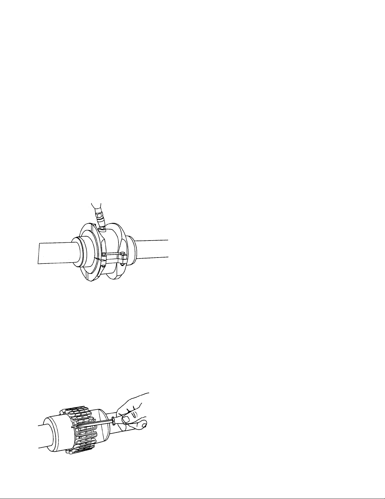
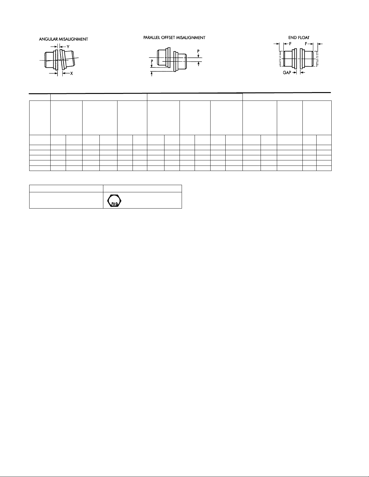
2 –Gap and Angular Alignment (x –y)
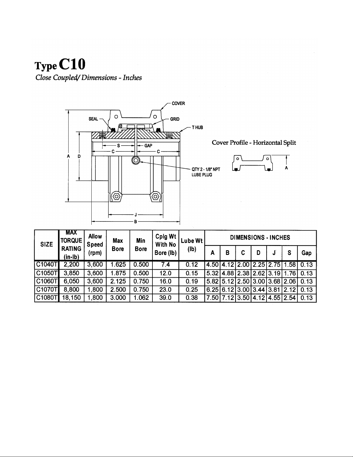
Use a spacer bar equal in thickness to the gap specified in
Table 2, Page 5. Insert bar as shown, above, to same
depth at 90° intervals and measure clearance between bar
and hub face with feelers. The difference in minimum
and maximum measurements must not exceed the
ANGULAR installation limits specified in Table 2.
Page 4 of 10
3 –Parallel Offset Alignment (P)
Align so that a straight edge rests squarely (or within the
limits specified in Table 2) on both hubs as shown above
and also at 90° intervals. Check with feelers. The
clearance must not exceed the PARALLEL OFFSET
installation limits specified in Table 2.
4 –Insert Grid
Completely pack gap and grooves with LTG Grease (or
equal) before inserting grid. When grids are furnished in
two or more segments, install them so that all cut ends
extend in the same direction (as detailed in the exploded
view picture above); this will assure correct grid contact
with non-rotating pin in cover halves. Spread the grid
slightly to pass over the coupling teeth and seat with a
soft mallet.
5 –Pack with Grease and Assemble Covers
Completely pack the spaces between and around the grid
with as much LTG Grease as possible and wipe off excess
flush with top of grid. Position seals on hubs to line up
with grooves in cover. Position gaskets on flange of
lower cover half and assemble covers so that the match
marks are on the same side (see above). If shafts are not
level (horizontal) or coupling is to be used vertically,
assemble cover halves with the lug and match mark UP or
on the high side. Push gaskets in until they stop against
the seals and secure cover halves with fasteners,
tightening to torque specified in Table 2. Make sure
gaskets stay in position during tightening of fasteners.
CAUTION: Make certain lube plugs are installed before
operating.
Page 5 of 10
ANNUAL MAINTENANCE
For extreme or unusual operating conditions, check
coupling more frequently.
1. Check alignment per steps on Page 3. If the maximum
operating misalignment limits are exceeded, realign the
coupling to the recommended installation limits. See
Table 2 for installation and operating alignment limits.
2. Check tightening torques of all fasteners.
3. Inspect seal rings and gaskets to determine if
replacement is required. If leaking grease, replace.
4. When connected equipment is serviced, disassemble
the coupling and inspect for wear. Replace worn parts.
Clean grease from coupling and repack with new LTG
grease. Install coupling using new gaskets as instructed in
this manual.
Periodic Lubrication
Cover halves have 1/8” NPT lube holes.
Use a standard grease gun and lube fitting as instructed,
below.
The required frequency of lubrication is directly related to
the type of lubricant chosen, and the operating conditions.
Tapered grid couplings lubricated with common industrial
lubricants, such as those shown in Table 1, should be
relubed annually. The use of LTG Grease provided by
Clarke will allow relube intervals to be extended to
beyond five years. When relubing, remove both lube
plugs and insert a standard lube fitting in one of the 1/8”
NPT openings. Fill with recommended lubricant until an
excess appears at the opposite hole. CAUTION: Make
certain all plugs have been inserted after lubricating.
Coupling Disassembly and Grid Removal
Whenever it is necessary to disconnect the coupling,
remove the cover halves and grid. A round rod or
screwdriver that will conveniently fit into the open loop
ends of the grid is required. Begin at the open end of the
grid section and insert the rod or screwdriver into the loop
ends. Use the teeth adjacent to each loop as a fulcrum
and pry the grid out radially in even, gradual stages,
proceeding alternately from side to side.
TYPE C10, C31 and C35 COUPLING
INSTALLATION & ALIGNMENT DATA
Maximum life, reduced equipment vibration, and
minimum maintenance for the coupling and connected
machinery will result if couplings are accurately aligned.
Coupling life expectancy between initial alignment and
maximum operating limits is a function of load, speed and
lubrication. Maximum operating values listed in Table 2
are based on cataloged allowable rpm. Values listed are
based upon the use of the gaps listed, standard coupling
components, standard assemblies and cataloged allowable
speeds. Values may be combined for an installation or
operating condition. Example: C1060T maximum
operating misalignment is .016” parallel offset plus .018”
angular.
Angular misalignment is dimension x minus y as
illustrated below. Parallel misalignment is distance P
between the hub center lines as illustrated below. End
float (with zero angular and parallel misalignment) is the
axial movement of the hub(s) within the cover(s)
measured from “0” gap.
Page 6 of 10
Table 2 –Misalignment & End Float
Installation Limits
Operating Limits
Size
Parallel
Offset
(P)
Angular
(x-y)
Hub Gap
10%
Parallel
Offset
(P)
Angular
(x-y)
End Float
Physical
Limit (Min)
2 x F
Cover
Fastener
Tightening
Torque Values
Inch or Metric
Series
Fasteners
Maximum
Allowable
Speed
(rpm)
Lube Wt.
Max
Inch
Max
Mm
Max
Inch
Max
Mm
Inch
mm
Max
Inch
Max
Mm
Max
Inch
Max
Mm
Inch
mm
in-lb
Nm
lb
kg
C1040T
.006
0,15
.003
0,08
.125
3
.012
0,30
.013
0,33
.211
5,36
100
11,3
3600
.12
0,05
C1050T
.008
0,20
.004
0,10
.125
3
.016
0,41
.016
0,41
.212
5,38
200
22,6
3600
.15
0,07
C1060T
.008
0,20
.005
0,13
.125
3
.016
0,41
.018
0,46
.258
6,55
200
22,6
3600
.19
0,09
C1070T
.008
0,20
.005
0,13
.125
3
.016
0,41
.020
0,51
.259
6,58
200
22,6
1800
.25
0,11
C1080T
.008
0,20
.006
0,15
.125
3
.016
0,41
.024
0,61
.288
7,32
200
22,6
1800
.38
0,17
Table 3 –Coupling Cover Fastener Identification
Size
Metric Fastener
C1040T –C1080 T
Property Class 10.9
PARTS IDENTIFICATION
All coupling parts have identifying part numbers as
shown below. When ordering parts, always SPECIFY
SIZE and TYPE shown on the COVER.
PARTS INTERCHANGEABILITY
GRIDS –Size C1040T thru C1080T tapered grid
couplings use blue or non-painted grids.
CAUTION: Blue or non-painted grids may be used in all
applications, but DO NOT substitute orange grids for
blue or non-painted.
COVERS –CAUTION:DO NOT mix cover halves of
different designs.
HARDWARE –The new style covers use hex head
metric cap screws. Specify the style cover when ordering
replacement parts.
Page 7 of 10
C10, C31, C35 COMPONENT PARTS
IDENTIFICATION
C10 PART DESCRIPTION:
1. Seal
2. Cover
3. Hub (Specify bore & Keyway)
4. Grid
5. Gasket
6. Metric Fasteners
7. Lube Plug
PARTS ORDERING INFORMATION:
1. Identify part(s) required by name
above.
2. Furnish the following information:
Example:
Coupling Size: C1030T
Bore 1.375”
Keyway: .375”x .187”
3. Contact Clarke Fire Protection
Products or Clarke UK LTD
Contact Info:
USA –Dave Goodfriend
Email: dgoodfriend@clarefire.com
Phone: 1.513.719.2352
Fax: 1.513.771.5375
UK –Duncan Murray
Email : [email protected]om
Phone : 44 (0) 1236 429946
Fax : 44 (0) 1236 427274
Page 8 of 10
DIMENSIONAL DATA / WEIGHTS
Page 9 of 10
Page 10 of 10
100 Progress Place, Cincinnati, OH 45246 Grange Works, Lomond Rd, Coatbridge, ML5-2NN
United States of America United Kingdom
Tel +1-513-475-3473 Fax + 1-513-771-0726 Tel +44-1236-429946 Fax +44-1236-427274
Specifications and information contained in this brochure subject to change without notice.

This manual suits for next models

2

Other Clarke Water Pump manuals

Clarke PSE1A Instruction Manual

Clarke

Clarke PSE1A Instruction Manual

Clarke LVP1A Instruction Manual

Clarke

Clarke LVP1A Instruction Manual

Clarke CPE20A1 Instruction Manual

Clarke

Clarke CPE20A1 Instruction Manual

Clarke CSV4A Instruction Manual

Clarke

Clarke CSV4A Instruction Manual

Clarke CGP870 Instruction Manual

Clarke

Clarke CGP870 Instruction Manual

Clarke ECP20A1 Instruction Manual

Clarke

Clarke ECP20A1 Instruction Manual

Clarke CVP1000 Quick guide

Clarke

Clarke CVP1000 Quick guide

Clarke BIP1500 Instruction Manual

Clarke

Clarke BIP1500 Instruction Manual

Clarke CPE Series Instruction Manual

Clarke

Clarke CPE Series Instruction Manual

Clarke CBM240E Instruction Manual

Clarke

Clarke CBM240E Instruction Manual

Clarke DWP210A Instruction Manual

Clarke

Clarke DWP210A Instruction Manual

Clarke CPE15A1 Instruction Manual

Clarke

Clarke CPE15A1 Instruction Manual

Clarke ISP10A Installation and operation manual

Clarke

Clarke ISP10A Installation and operation manual

Clarke PSV5A Instruction Manual

Clarke

Clarke PSV5A Instruction Manual

Clarke ISP11A Manual

Clarke

Clarke ISP11A Manual

Clarke SWP900A Instruction Manual

Clarke

Clarke SWP900A Instruction Manual

Clarke DWP300A Instruction Manual

Clarke

Clarke DWP300A Instruction Manual

Clarke TAM100 7230035 Installation and operation manual

Clarke

Clarke TAM100 7230035 Installation and operation manual

Clarke PSP105 Instruction Manual

Clarke

Clarke PSP105 Instruction Manual

Clarke PF75 Instruction Manual

Clarke

Clarke PF75 Instruction Manual

Clarke DFT12 Instruction Manual

Clarke

Clarke DFT12 Instruction Manual

Clarke PS75 Instruction Manual

Clarke

Clarke PS75 Instruction Manual

Clarke CPE20A3 Instruction Manual

Clarke

Clarke CPE20A3 Instruction Manual

Clarke CSV1A Instruction Manual

Clarke

Clarke CSV1A Instruction Manual

Popular Water Pump manuals by other brands

Lutz-Jesco MEMDOS SMART LK operating instructions

Lutz-Jesco

Lutz-Jesco MEMDOS SMART LK operating instructions

BVA Hydraulics P570FP instruction manual

BVA Hydraulics

BVA Hydraulics P570FP instruction manual

Einhell Royal HWA 810 operating instructions

Einhell Royal

Einhell Royal HWA 810 operating instructions

GORMAN-RUPP HO3/4A4-36DK PARTS LIST AND MAINTENANCE MANUAL

GORMAN-RUPP

GORMAN-RUPP HO3/4A4-36DK PARTS LIST AND MAINTENANCE MANUAL

Eckerle Gotec SP32/01 technical information

Eckerle

Eckerle Gotec SP32/01 technical information

Graco GBL 7500 instructions

Graco

Graco GBL 7500 instructions

Espa CKE Series instruction manual

Espa

Espa CKE Series instruction manual

Teryair DP 12 Metal Series Operation and maintenance guide

Teryair

Teryair DP 12 Metal Series Operation and maintenance guide

Grundfos AP80-100 Safety instructions and other important information

Grundfos

Grundfos AP80-100 Safety instructions and other important information

Homa Saniquick A Installation and operation instruction manual

Homa

Homa Saniquick A Installation and operation instruction manual

Gasboy 61 Special installation instructions

Gasboy

Gasboy 61 Special installation instructions

KSB Omega Installation & operating manual

KSB

KSB Omega Installation & operating manual

FUXTEC FX-WP152 Original user manual

FUXTEC

FUXTEC FX-WP152 Original user manual

Grundfos JPA Series Safety instructions and other important information

Grundfos

Grundfos JPA Series Safety instructions and other important information

Flotec FPWG-145SP owner's manual

Flotec

Flotec FPWG-145SP owner's manual

ProMinent vonTaine 1010 PP Assembly and operating instructions

ProMinent

ProMinent vonTaine 1010 PP Assembly and operating instructions

AxFlow Aturia ND Series Operation & maintenance manual

AxFlow

AxFlow Aturia ND Series Operation & maintenance manual

PYD Electrobombas KS Series Operating and maintenance manual

PYD Electrobombas

PYD Electrobombas KS Series Operating and maintenance manual

manuals.online logo
manuals.online logoBrands
  • About & Mission
  • Contact us
  • Privacy Policy
  • Terms and Conditions

Copyright 2025 Manuals.Online. All Rights Reserved.