© Copyright 2015. All rights reserved.
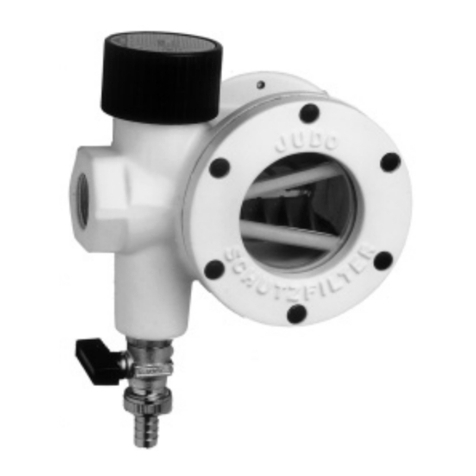
Pressure Switch Installation P/N 5000-0006
1. Install the Pressure Switch in the upper part of the tank riser.
2. Attach the switch mount to the side of the riser. If the riser is plastic,
secure it with a SS screw. If the riser is cement, use a plastic anchor
and SS screw. Seal any holes through the riser.
3. Attach the switch
to the mount.
Secure with strap if
necessary.
4. Route the 1/4" tubing
down to the 1/4" port
on the lter or where
the pressure is to be
monitored. Remove
the plug. Apply Teon
tape to the male
threads on the 90°
tting. Install the 90°
tting in the 1/4" port.
Install the 1/4" tube
in the 90° tting and
tighten to seal.
Be sure the tubing
does not interfere
with moving parts,
oats, valves, etc.
6. To adjust the switch:
A. Remove the 1/8" plug on
top of the switch and insert
the 7/32" hex wrench.
B. Start the pump. Let it
run for one minute to
allow the pipes to ll. If
the alarm sounds, turn
the switch adjustment
screw clockwise one turn
to increase the switch
resistance pressure.
Reset the alarm and repeat
this step until no alarm is triggered by the switch.
C. With the pump running and the alarm reset, turn the wrench
counter-clockwise until the alarm sounds (or lights). This is the
running pressure.
D. Now turn the wrench one full turn clockwise . This is approximately
3 psi above the running pressure. If nuisance tripping of the alarm
occurs, increase the switch resistance pressure by turning the switch
adjustment screw clockwise by small degrees until it stops.
E. IMPORTANT! Replace the 1/8" plug after adjusting the switch.
5. Route the wire safely
out of the tank with other
wires to the alarm. The
pressure switch can be
wired with a high level
oat or on its own.
SK2208C
SK2208B
WATERTIGHT
JUNCTION BOX
PANEL
HIGH WATER
ALARM FLOAT
PRESSURE
SWITCH
WHITE
WIRES
BLACK
WIRES
DECREASE
INCREASE
Limited Warranty
Manufacturer warrants, to the purchaser and subsequent owner during the warranty
period, every new product to be free from defects in material and workmanship under
normal use and service, when properly used and maintained, for a period of one year
from date of purchase by the end user, or 18 months from date of original manufacture
of the product, whichever comes rst. Parts that fail within the warranty period, one
year from date of purchase by the end user, or 18 months from the date of original
manufacture of the product, whichever comes rst, that inspections determine to be
defective in material or workmanship, will be repaired, replaced or remanufactured at
manufacturer's option, provided however, that by so doing we will not be obligated to
replace an entire assembly, the entire mechanism or the complete unit. No allowance
will be made for shipping charges, damages, labor or other charges that may occur
due to product failure, repair or replacement.
This warranty does not apply to and there shall be no warranty for any material or
product that has been disassembled without prior approval of manufacturer, subjected
to misuse, misapplication, neglect, alteration, accident or act of God; that has not
been installed, operated or maintained in accordance with manufacturer's installation
instructions; that has been exposed to outside substances including but not limited to
the following: sand, gravel, cement, mud, tar, hydrocarbons, hydrocarbon derivatives
(oil, gasoline, solvents, etc.), or other abrasive or corrosive substances, wash towels
or feminine sanitary products, etc. in all pumping applications. The warranty set out
in the paragraph above is in lieu of all other warranties expressed or implied; and we
do not authorize any representative or other person to assume for us any other liability
in connection with our products.
Contact manufacturer at, 3649 Cane Run Road, Louisville, Kentucky 40211, Attention:
Customer Support Department to obtain any needed repair or replacement of part(s) or
additional information pertaining to our warranty.
MANUFACTURER EXPRESSLY DISCLAIMS LIABILITY FOR SPECIAL,
CONSEQUENTIAL OR INCIDENTAL DAMAGES OR BREACH OF EXPRESSED
OR IMPLIED WARRANTY; AND ANY IMPLIED WARRANTY OF FITNESS FOR A
PARTICULAR PURPOSE AND OF MERCHANTABILITY SHALLBE LIMITED TO THE
DURATION OF THE EXPRESSED WARRANTY.
Some states do not allow limitations on the duration of an implied warranty, so the above
limitation may not apply to you. Some states do not allow the exclusion or limitation
of incidental or consequential damages, so the above limitation or exclusion may not
apply to you.
This warranty gives you specic legal rights and you may also have other rights which
vary from state to state.
SK2208D
All Clarus Environmental products must be installed and maintained in accordance with all applicable codes.
Product information presented here reflects conditions at time of publication. Consult factory regarding discrepancies or inconsistencies.
TO POWER
/ALARM
1/4" PORT
1/4" TUBE


