Classic AutoAir Flex FIt Series User manual

Installation Manual
Custom Colder The Climate Control System
DOCUMENT #1-1090
©2016 ClassicAutoAir / 07.16
©
©


You have just purchased the highest quality, best performing
A/C system ever designed for your classic vehicle.
To obtain the high level of performance and dependability our systems are known for, please pay close attention to the
following instructions. Our installation steps and procedures are derived from a long history of research and
development and the combined experience achieved thru thousands of successful installations (and feedback from
customers like you). Please remember that our #1 goal is that you’ll have a successful installation and a system that
performs at a very high level for many years to come.
Before starting, read the instructions carefully, from beginning to end, and follow the proper sequence. On the next
page you’ll find a safety and general checklist that you should read before starting your installation.
Again, thank you from our entire staff.
CLASSIC AUTO AIR
Page 1

Check List, Pre-Installation:
Procedures, During Installation:
Before beginning the installation check the shipping box for the correct components. YOUR BOXED UNIT INCLUDES A LIST OF
MAJOR COMPONENTS AND A LIST OF BAGGED PARTS. We have a 5 stage check process to make sure you have everything you’ll
need.
If your vehicle has been or is being modified, some procedures will need to be adjusted to fit your particular application.
A basic cleaning of the engine compartment and interior before beginning will make things go more smoothly.
Check condition of engine mounts. Excessive engine movement can damage hoses to A/C and/or heater.
Before starting, check vehicle interior electrical functions (interior lights, radio, horn, etc). Make a note of anything that does not work as
it’s supposed to. During the installation you might find the opportunity to repair or upgrade non-working or out of date components.
When you’re ready to start the installation, DISCONNECT THE BATTERY FIRST.
Drain the radiator. Retain the coolant and reuse, or dispose of properly.
SAFETY FIRST: Wear eye protection while drilling/cutting, deburr sharp edges, and never get in a hurry or force a part.
Tools: Your installation only requires the basic tools everyone has in their garage, nothing exotic or specific to A/C or Heat equipment.
Fittings: Use one or two drops of mineral oil (supplied with your kit) on ALL rubber o-rings, threads and rear of bump for o-ring where
female nut rides. Do not use thread tape or sealants.
Measure twice (or more), cut once
Should you have any technical questions, or feel you have defective components (or missing items), call us immediately,
we will be glad to assist you. Our toll-free number is listed on every page, we’re here to help!
YOU CAN NOW BEGIN THE INSTALLATION...
CLASSIC AUTO AIR
Page 2

The air conditioning system in your car is comprised of a compressor,
condenser, expansion valve, receiver/drier, and evaporator. Refrigerant (also
known as Freon) is compressed in the compressor. In the condenser, gas is
cooled to a liquid state and travels to the expansion valve. As the liquid refrigerant
goes through the expansion valve it rapidly cools in the evaporator. A fan blows
over the evaporator and cools the air that blows out your vents
Evaporator with Blower Fan
In order to remove the heat from the air in the vehicle, the
A/C evaporator allows the refrigerant to absorb the heat from the air passing over it. The blower fan
moves cool air out into the car interior.
Compressor
The compressor pumps and circulates the refrigerant through the system.
Condenser
The condenser is a heat exchanger mounted at the front of the vehicle. Heat drawn
out of the interior of the car is expelled here.
Receiver/Drier
The drier not only dries refrigerant, it also filters the refrigerant and stores it
under certain operating conditions.
High Pressure Switch
A pressure switch is used to shut down the system if high or low
pressure is detected, basically it acts as a safety switch.
A Basic Overview of Automotive A/C....
Receiver
Drier
Compressor
Evaporator Unit
Expansion Valve
Condenser
Suction
Valve Discharge
Valve
Firewall
OUTSIDE AIR
COLD AIR INTO VEHICLE
AIR FROM INSIDE VEHICLE
GROUND
POWER
SUCTION HOSE
DISCHARGE HOSE
LIQUID HOSE
1
1
2
3
4
5
2
3
4
5
COOLED AIR
CLASSIC AUTO AIR
Page 3
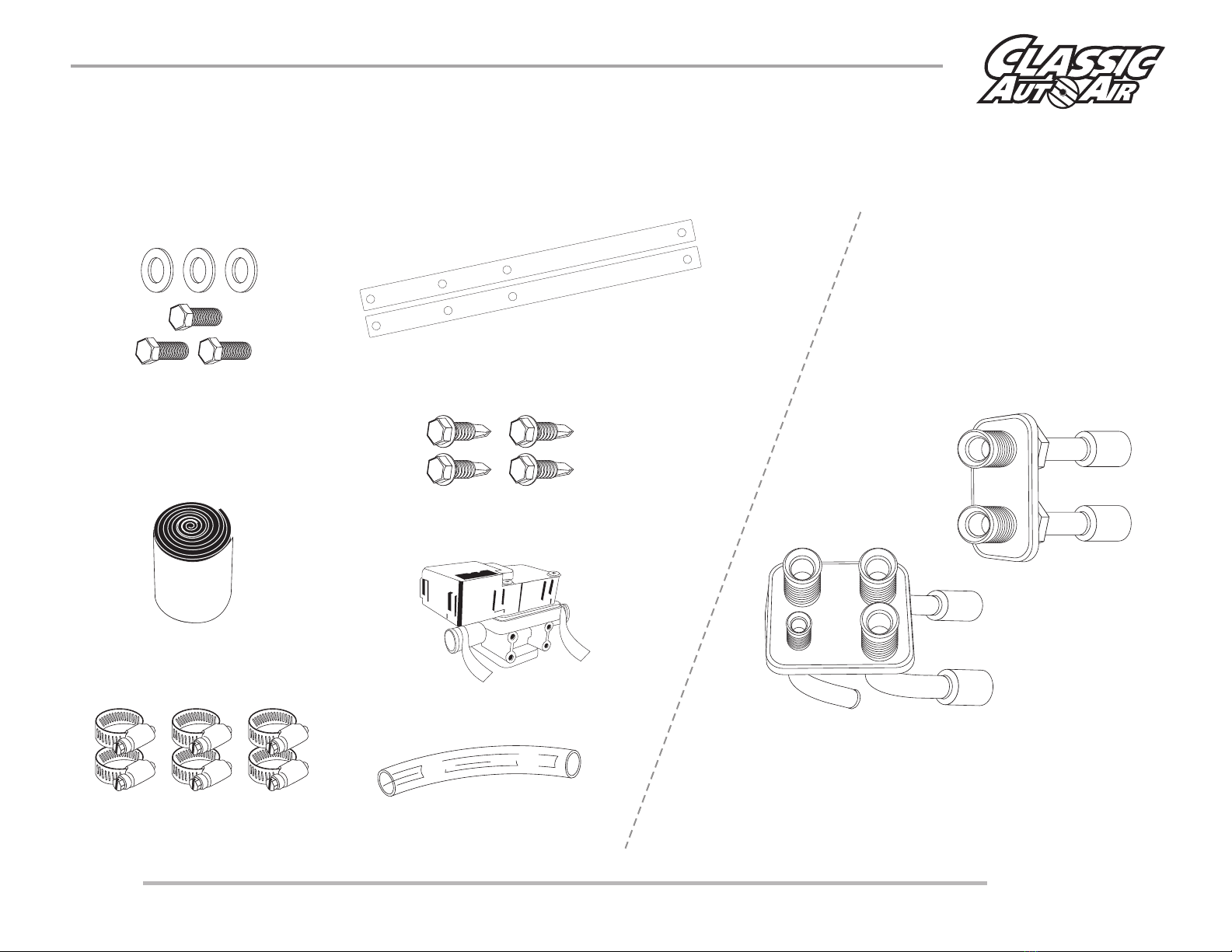
THESE ARE THE PARTS YOU WILL FIND IN BAG KIT A
You will use all of these parts and hardware during the next series of installation steps.
Electronic Water Control Valve
Six Worm Gear Clamps
Three 1/4 - #20 x 1" Bolts
and Washers
Clear Plastic Drain Tube
Refrigerant Tape
If you purchased these
OPTIONAL bulkhead plates they
will be located in unit box.
CLASSIC AUTO AIR
Page 4
Two Installation Brackets
Four #10 - 16 x 3/4" Tek Screws
H
E
A
T
E
R
C
O
R
E
W
A
T
E
R
P
U
M
P
CLASSIC AUTO AIR
Page 5
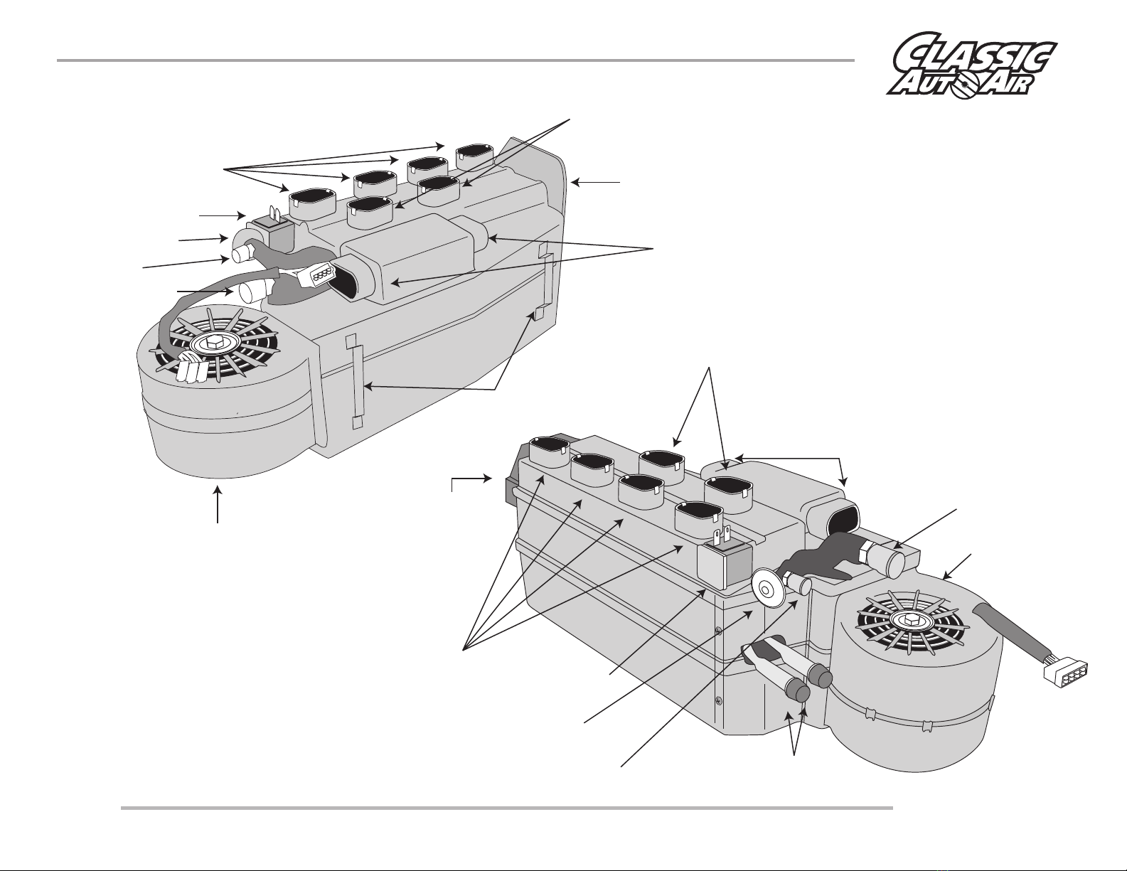
Floor Hose Connection
Thermostat
Blower Motor
Actuator Motors
Expansion Valve
Blower Motor
Dash Hose Connections
Actuator
Motors
Suction Line
Heater Hose Connections
Thermostat
Defrost Hose Connections
Expansion Valve
Liquid Pressure
Line
Liquid Pressure
Line
Dash Hose Connections
Mounting Brakets
Floor Hose Connection
Suction Line
Defrost Hose Connections

Calibration Key
Blue
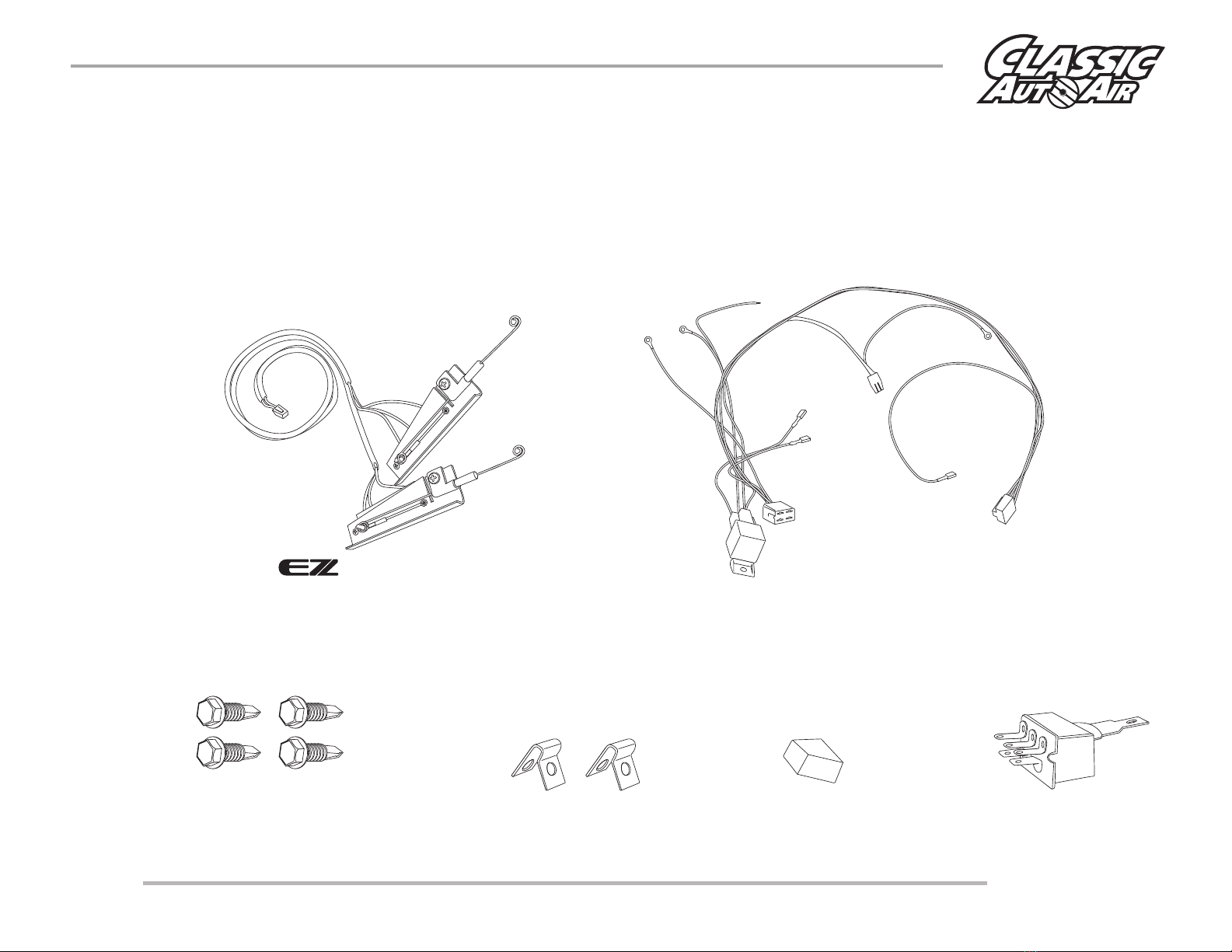
THESE ARE THE PARTS YOU WILL FIND IN BAG KIT B
You will use all of these parts and hardware during the next series of installation steps.
FACE/FLOOR
POWER
CONTROL
WATER VALVE
DEFROST
The ECU will be attached for shipping
purposes to the body of the
main unit. You will need to detach and mount
near your evaporator unit.
Harness System
Yellow
Orange
Two #10 - 16 x 3/4" Tek Screws
CLASSIC AUTO AIR
Page 6
NOTE: Illustrations NOT shown actual size
Blower Switch
Blower Switch Knob
Two - Cable Clips
CONTROLS
You will use these parts and hardware during the next series of installation steps.
Wiring Harness -
Power Supply
GroundGround Ground
OEM Power
Supply
ECU
Pressure Switch
(engine compartment)
Thermostat
Relay
Blower Switch
Connection
Fan
Plug
Four #10 - 16 x 3/4" Tek Screws
CLASSIC AUTO AIR
Page 7
Cable Integrators
EZ CABLE INTAGRATOR WITH LEVER SWITCH

NOTE: Illustrations NOT shown actual size
Two - Cable Clips
CONTROLS
You will use these parts and hardware during the next series of installation steps.
Rotary Wiring Harness -
Power Supply
GroundGround Ground
OEM Power
Supply
ECU
Pressure Switch
(engine compartment)
Thermostat
Relay
Blower Switch
Connection
Fan
Plug
Four #10 - 16 x 3/4" Tek Screws
CLASSIC AUTO AIR
Page 8
Cable Integrators
Rotary Blower Switch Rotary Blower Switch Knob
EZ CABLE INTAGRATOR WITH ROTARY SWITCH

NOTE: Illustrations NOT shown actual size
CONTROLS
You will use these parts and hardware during the next series of installation steps.
Wiring Harness -
Power Supply
GroundGround Ground
OEM Power
Supply
ECU
Pressure Switch
(engine compartment)
Thermostat
Relay
Blower Switch
Connection
Fan
Plug
Four #10 - 16 x 3/4" Tek Screws
CLASSIC AUTO AIR
Page 9
BILLET CONTROLS
Billet Controls
OFF 1
2
3
Adapting to OEM Contols:
If you specified our EZ Wire Cable system, we’ve included all the parts necessary for you to retain your OEM controls and adapt to your new A/C system. In order to
do this, you’ll need to remove your OEM temperature control head and move it to a workbench and follow thru the steps listed below. Because there is such a wide
variety of controls, these steps may have to be modified to adapt your particular controls. Adhere to some simple rules and you’ll be done in a short amount of time.
•Step 1: Remove the OEM blower switch and discard. Attach the included blower switch to your control head in place of the OEM switch. This may require some
fabrication.
•Step 2: Looking at your OEM controls, identify which lever you want to use to control TEMPERATURE and which to control the MODE. Then from the back of the
control head, mark the appropriate levers with masking tape and their intended function (i.e. mode and temp).
•Step 3: Attach the included cable clips to each adaptor as shown in. You’ll use the these cable adaptors to secure the integrators to your OEM control head, or
you may have to attach the integrators in another manner. v
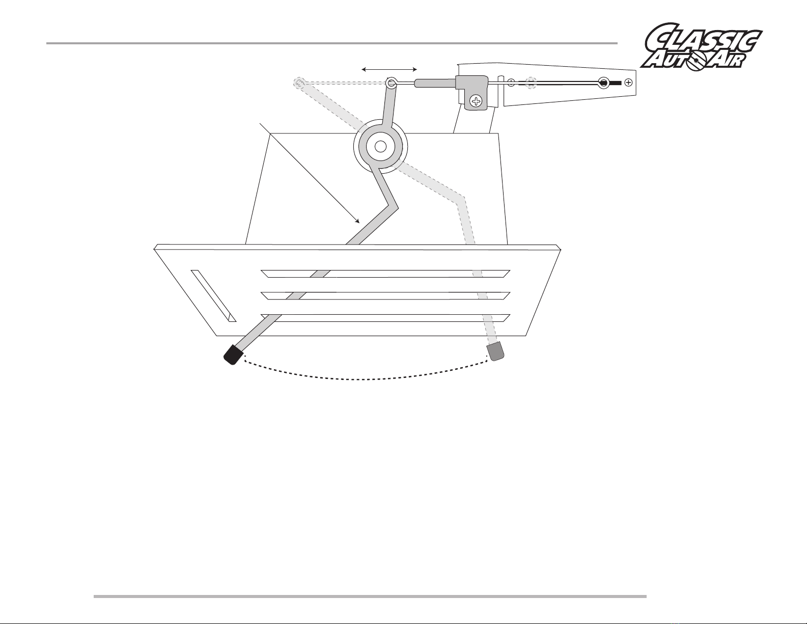
•Step 4: Position our EZ Wire Cable Adaptors in a manner that the wire-ends can be secured to the appropriate lever ends, and when you move the OEM levers
from one extreme to the other that the wire can move the actuators in a smooth and straight manner. The most important aspect is that your OEM levers,
which ever two you choose to use, move their entire possible distance of travel (when viewed from the front of the control head).
CLASSIC AUTO AIR
Page 10
FULL MOTION
EZ CABLE INTERGRATOR WILL BE
CALIBRATED TO MOTION OF OEM ARM.
OEM CONTROL MODIFICATIONS

Bench Calibration Steps 1
1
Connect Yellow Harness into Defrost/Heat Servo Motor
Connect Blue Harness into Dash Servo Motor
Click!
CLASSIC AUTO AIR
Page 11
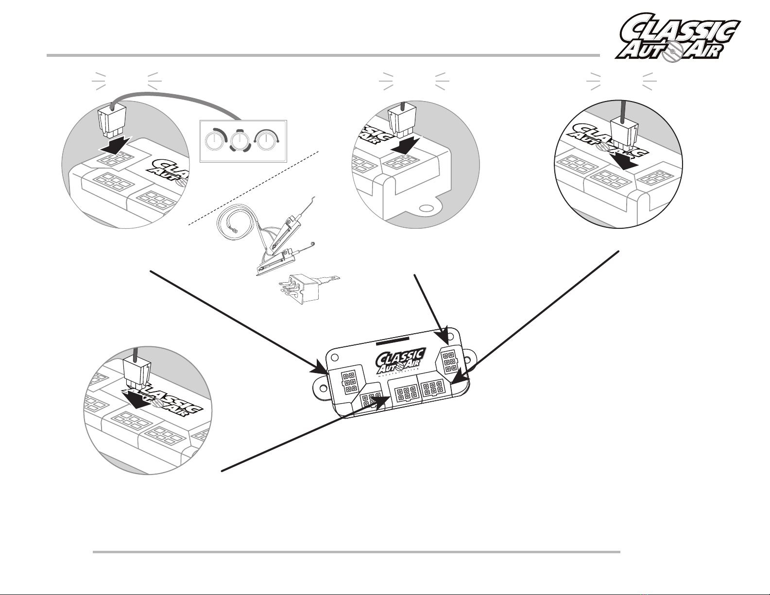
Bench Calibration Steps 2 thru 5
FACE/FLOOR
POWER
CONTROL
WATER VALVE
DEFROST
2
Connect Yellow Harness into Face / Floor Port on ECU
Power
Control Water Valve
Face/Floor Defrost
Click!
3
Connect Orange Harness into Water Valve Port on ECU
Next route other end of harness out of firewall
opening
Power
Control Water Valve
Face/Floor Defrost
Click!
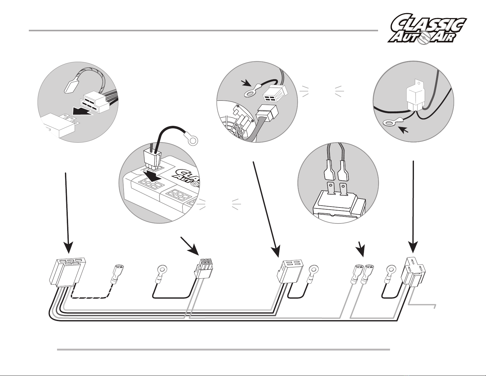
The next step is to utilize the main
wiring harness and the two
wire control harnesses we’ve
included, wiring per this diagram.
You have three ground wire
connections on the main harness
to make, one relay to secure, and
one power supply to connect to
your OEM fuse box. The wiring
harneses are color coded, just
follow the connections as
specified.
4
5
Click!
From your Controls,
Connect Green Harness into
Control Port on ECU
Power
Control Water Valve
Face/Floor Defrost
CLASSIC AUTO AIR
Page 12
Connect Blue Harness into Defrost Port on ECU
Power
Control Water Valve
Face/Floor Defrost
CLASSIC AUTO AIR
Page 13
2
3
4
15
12V
Power
Control Water Valve
Face/Floor Defrost
Grd -
Grd
Grd
Connect both BLUE leads into thermostat
(either lead into either terminal)
Connect ground.
Connect corresponding Fan Switch
harness to the Bower Switch on Controls
Connect Power lead
to 12V.
Connect corresponding fan motor harness.
Connect ground.
Connect red tagged power harness to POWER port on ECU.
Connect ground.
Grd -Grd -
12V Power
(20 amp fuse) Grd -
(Single white lead
is to be connected to the
pressure switch on the drier)
Click!
Click!

THE FOLLOWING BENCH CALIBRATION & OPERATION PAGES
ARE FOR BILLET AND SPECIALTY CONTROLS.
IF YOU PURCHASED A EZ CABLE INTEGRATOR SET UP
PLEASE SKIP TO PAGES 18-22.
ATTENTION
CLASSIC AUTO AIR
Page 14
OFF 1
2
3
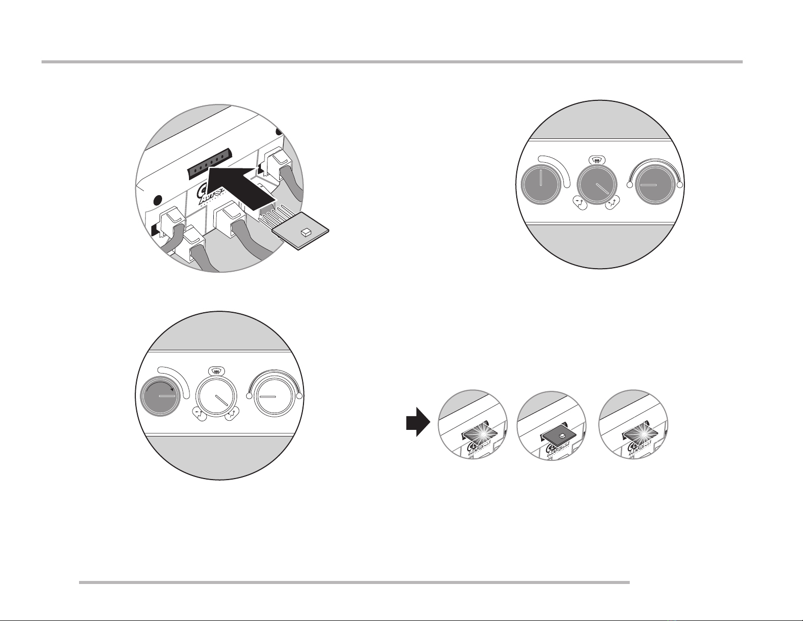
BENCH CALIBRATION & OPERATION •Calibration, Steps 1 thru 3
CLASSIC AUTO AIR
Page 15
CONTROL
POWER
DEFROST
WATER VALVE
FACE/FLOOR
Calibration KeyCalibration Key
LED OFF
1
3
Insert Calibration Key as shown (LED side up) into 6-pin
connection in ECU
CONTROL
POWER
DEFROST
WATER VALVE
FACE/FLOOR
YOU WILL SEE...
CONTROL
POWER
DEFROST
WATER VALVE
FACE/FLOOR
Calibration KeyCalibration Key
LED ON
CONTROL
POWER
DEFROST
WATER VALVE
FACE/FLOOR
Calibration KeyCalibration Key
LED ON
Calibration KeyCalibration Key
2
Start by positioning the knobs as shown:
Fan: Off
Mode: Floor
Temp: Cold
Move Fan Knob to High...
OFF 1
2
3C H
OFF 1
2
3C H

BENCH CALIBRATION & OPERATION •Calibration, Steps 4 and 5
CLASSIC AUTO AIR
Page 16
4
5
CONTROL
POWER
DEFROST
WATER VALVE
FACE/FLOOR
Calibration KeyCalibration Key
LED OFF
Move MODE knob to DASH
in one motion
AFTER YOU MOVE THE KNOB YOU WILL SEE...
CONTROL
POWER
DEFROST
WATER VALVE
FACE/FLOOR
Calibration KeyCalibration Key
LED ON
CONTROL
POWER
DEFROST
WATER VALVE
FACE/FLOOR
Calibration KeyCalibration Key
LED OFF
Move TEMP knob to HOT
in one motion
AFTER YOU MOVE THE KNOB YOU WILL SEE...
OFF 1
2
3C H
OFF 1
2
3C H

BENCH CALIBRATION & OPERATION •Calibration, Steps 6 thru 8
CLASSIC AUTO AIR
Page 17
6
CONTROL
POWER
DEFROST
WATER VALVE
FACE/FLOOR
Calibration KeyCalibration Key
7
8
CONTROL
POWER
DEFROST
WATER VALVE
FACE/FLOOR
Calibration KeyCalibration Key
LED OFF
Move FAN knob to OFF
REMOVE CALIBRATION KEY FROM ECU AND
STORE IN A SAFE PLACE
You will be able to hear the
internal door(s) move back
and forth and feel air
coming out of the outlets
OFF 1
2
3C H
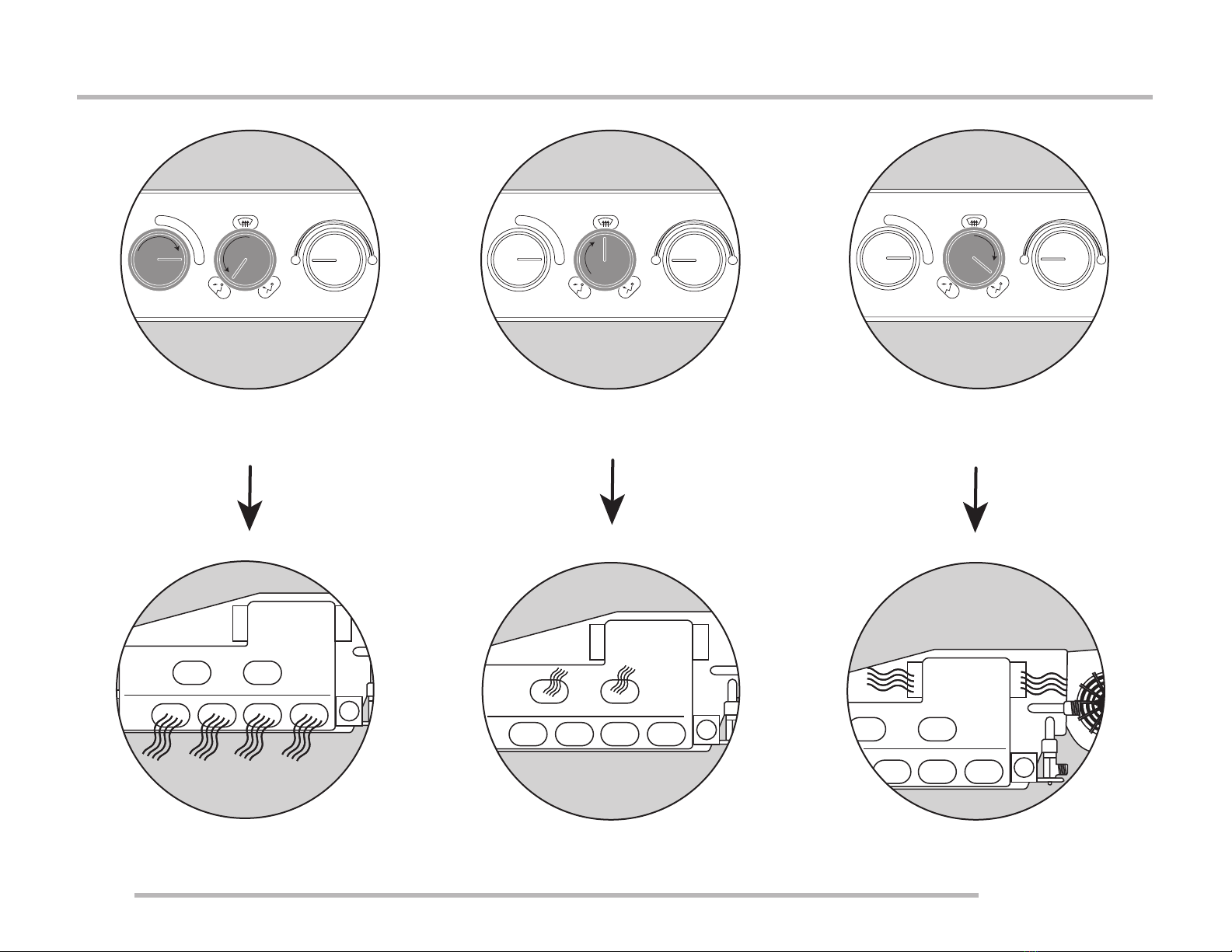
BENCH CALIBRATION & OPERATION •Function Test, Steps 1 thru 3
CLASSIC AUTO AIR
Page 18
2 3
Move FAN knob to HIGH
Move MODE knob to DASH
Move MODE knob to DEFROST Move MODE knob to FLOOR
AIR OUT OF DASH VENTS AIR OUT OF DEFROST VENTS AIR OUT OF FLOOR
1
OFF 1
2
3C H
OFF 1
2
3C H
OFF 1
2
3C H
This manual suits for next models
1
Table of contents
Other Classic AutoAir Automobile Accessories manuals

Popular Automobile Accessories manuals by other brands


Whelen Engineering Company
Whelen Engineering Company SA315 installation guide

Diode Dynamics
Diode Dynamics Demon Eyes installation guide

Innovate Motorsports
Innovate Motorsports PSB-1 user manual

Havis-Shields
Havis-Shields Side Slide-Out Step 1997-2007 Chevrolet Full Size Van... installation instructions

Yakima
Yakima LOCKN'LOAD instructions

Dobinsons
Dobinsons BU59-3506 installation guide


