Classic AutoAir Perfect Fit Elite Series User manual

1968-74 Corvette
DOCUMENT #1-2053
©


PAGE
3
You have just purchased the highest quality, best performing
A/C system ever designed for your Corvette.
To obtain the high level of performance and dependability our systems are known for, please pay close
attention to the following instructions. Our installation steps and procedures are derived from a long history of
research and development and the combined experience achieved thru thousands of successful installations
(and feedback from customers like you). Please remember that our #1 goal is that you’ll have a successful
installation and a system that performs at a very high level for many years to come.
Before starting, read the instructions carefully, from beginning to end, and follow the proper sequence. On the
next page you’ll find a safety and general checklist that you should read before starting your installation.
Again, thank you from our entire staff.
www.classicautoair.com • 866.435.7801
PAGE
4
Check List, Pre- Installation:
Procedures, During Installation:
Before beginning the installation check the shipping box for the correct components. YOUR BOXED UNIT INCLUDES A LIST
OF MAJOR COMPONENTS AND A LIST OF BAGGED PARTS. We have a 5 stage check process to make sure you have
everything you’ll need.
If your vehicle has been or is being modified, some procedures will need to be adjusted to fit your particular application.
A basic cleaning of the engine compartment and interior before beginning will make things go more smoothly.
Check condition of engine mounts. Excessive engine movement can damage hoses to A/C and/or heater.
Before starting, check vehicle interior electrical functions (interior lights, radio, horn, etc). Make a note of anything that does
not work as it’s supposed to. During the installation you might find the opportunity to repair or upgrade non-working or out of
date components. When you’re ready to start the installation, DISCONNECT THE BATTERY FIRST.
Drain the radiator. Retain the coolant and reuse, or dispose of properly.
SAFETY FIRST: Wear eye protection while drilling/cutting, deburr sharp edges, and never get in a hurry or force a part.
Tools: Your installation only requires the basic tools everyone has in their garage, nothing exotic or specific to A/C or Heat
equipment.
Fittings: Use one or two drops of mineral oil (supplied with your kit) on ALL rubber o-rings, threads and rear of bump for o-ring
where female nut rides. Do not use thread tape or sealants.
Measure twice (or more), cut once
Should you have any technical questions, or feel you have defective components (or missing items), call us immediately,
we will be glad to assist you. Our toll-free number is listed on every page, we’re here to help!
YOU CAN NOW BEGIN THE INSTALLATION...
www.classicautoair.com • 866.435.7801

PAGE
5
www.classicautoair.com • 866.435.7801
The air conditioning system in your car is comprised of a compressor,
condenser, expansion valve, receiver/drier, and evaporator. Refrigerant (also
known as Freon) is compressed in the compressor. In the condenser, gas is
cooled to a liquid state and travels to the expansion valve. As the liquid refrigerant
goes through the expansion valve it rapidly cools in the evaporator. A fan blows
over the evaporator and cools the air that blows out your vents
Evaporator with Blower Fan
In order to remove the heat from the air in the vehicle,
the A/C evaporator allows the refrigerant to absorb the heat from the air passing over it. The blower fan
moves cool air out into the car interior.
Compressor
The compressor pumps and circulates the refrigerant through the system.
Condenser
The condenser is a heat exchanger mounted at the front of the vehicle. Heat drawn
out of the interior of the car is expelled here.
Receiver/Drier
The drier not only dries refrigerant, it also filters the refrigerant and stores it
under certain operating conditions.
High Pressure Switch
A pressure switch is used to shut down the system if high or low
pressure is detected, basically it acts as a safety switch.
A Basic Overview of Automotive A/C....
Receiver
Drier
Compressor
Evaporator Unit
Expansion Valve
Condenser
Suction
Valve Discharge
Valve
Firewall
OUTSIDE AIR
COLD AIR INTO VEHICLE
AIR FROM INSIDE VEHICLE
GROUND
POWER
SUCTION HOSE
DISCHARGE HOSE
LIQUID HOSE
1
1
2
3
4
5
2
3
4
5
COOLED AIR
Control & Operating
Instructions
Your new Perfect Fit-Elite system offers
complete comfort capabilities in virtually
every driving condition. This includes
temperature control in all of the modes. This
system also provides the ability to blend the
air between Face, Heat, and Defrost modes
simultaneously. To illustrate the various ways
you can adjust the airflow direction and
temperature - we’ve provided these handy
illustrations and chart to show exactly how
you can adjust your Perfect Fit-Elite for
ON ON
Left Lever Position
Distribution
Compressor State
1 2 3 4 5 6 7 8 9 10 11
Dash
100%
Dash
90%
Defrost/Floor
10%
Dash
80%
Defrost/Floor
20%
Dash
70%
Defrost/Floor
30%
Dash
60%
Defrost/Floor
40%
Defrost
50%
Dash
50%
Defrost
100%
Dash
40%
Defrost
60%
Dash
20%
Defrost
80%
Dash
30%
Defrost
70%
Dash
10%
Defrost
90%
Floor
100%
DASH DEF/
FLOOR
PAGE
6
There are 11 levels of adjustment within
the range of the DASH/DEF lever
The FAN switch works like the OEM switch,
the far left position is OFF (all power to the
system is OFF in this position)
The COLD/HOT positions works like
any traditional adjustment lever
www.classicautoair.com • 866.435.7801
MODE LEVER
FAN SWITCH
TEMP LEVER
DEF HOT
OFF HI
COLD
DASH

PAGE
7
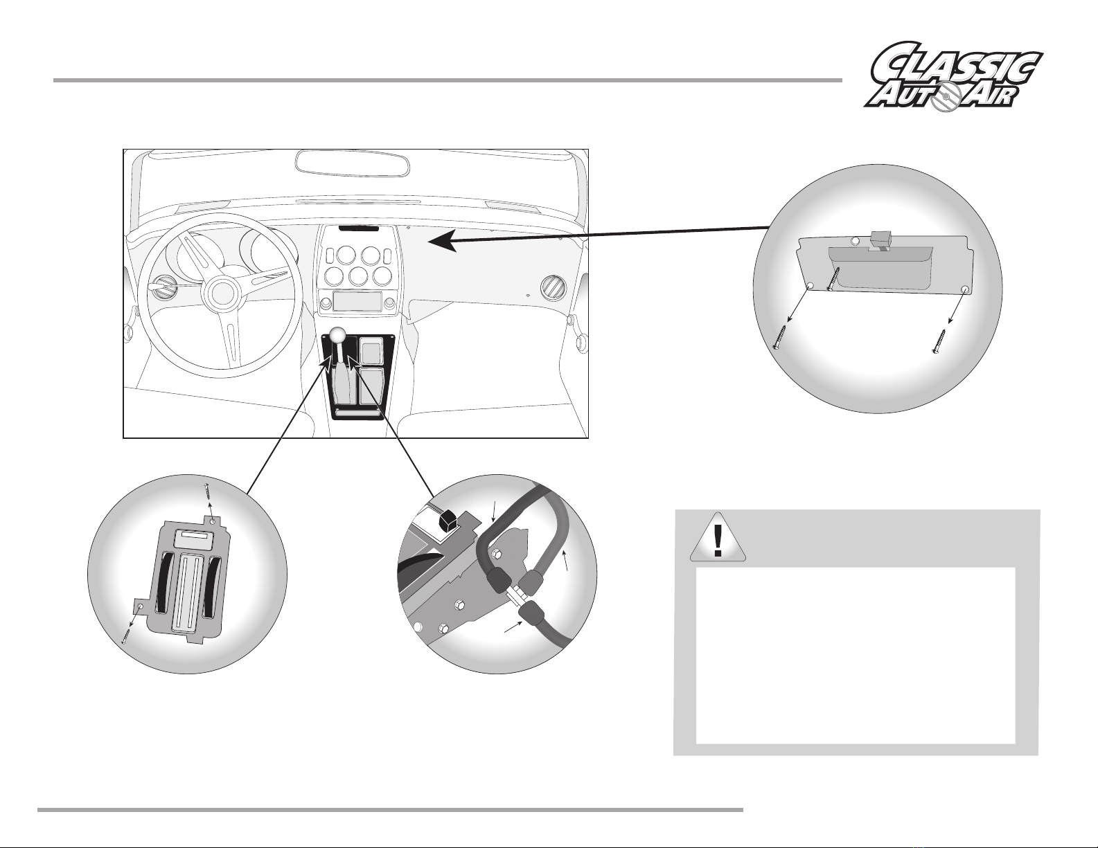
Remove Glovebox, Console
(optional) Radio and Bezel, and
set them aside for reinstall later
(see figure 1).
The removal of the Original Heater Assembly can be
accomplished by disconnecting three control cables.
One is attached to the Heat/Defrost door (see figure 2).
One is attached to the Temperature door, and one is
attached to the Vent / Heat door (see figure 3).
Disconnect the electrical harness from the assembly.
Also remove attachment screw located in front of the
INTERIOR
COMPARTMENT
When retaining parts it’s a
good idea to store parts in
a zip lock bag, labeled
with info where the parts
came from and what
size/type of tool is needed to
reinstall. Cleaning the parts before
you need to reinstall them is a good
GOOD IDEA
FIGURE 4
FIGURE 3
FIGURE 2
www.classicautoair.com • 866.435.7801

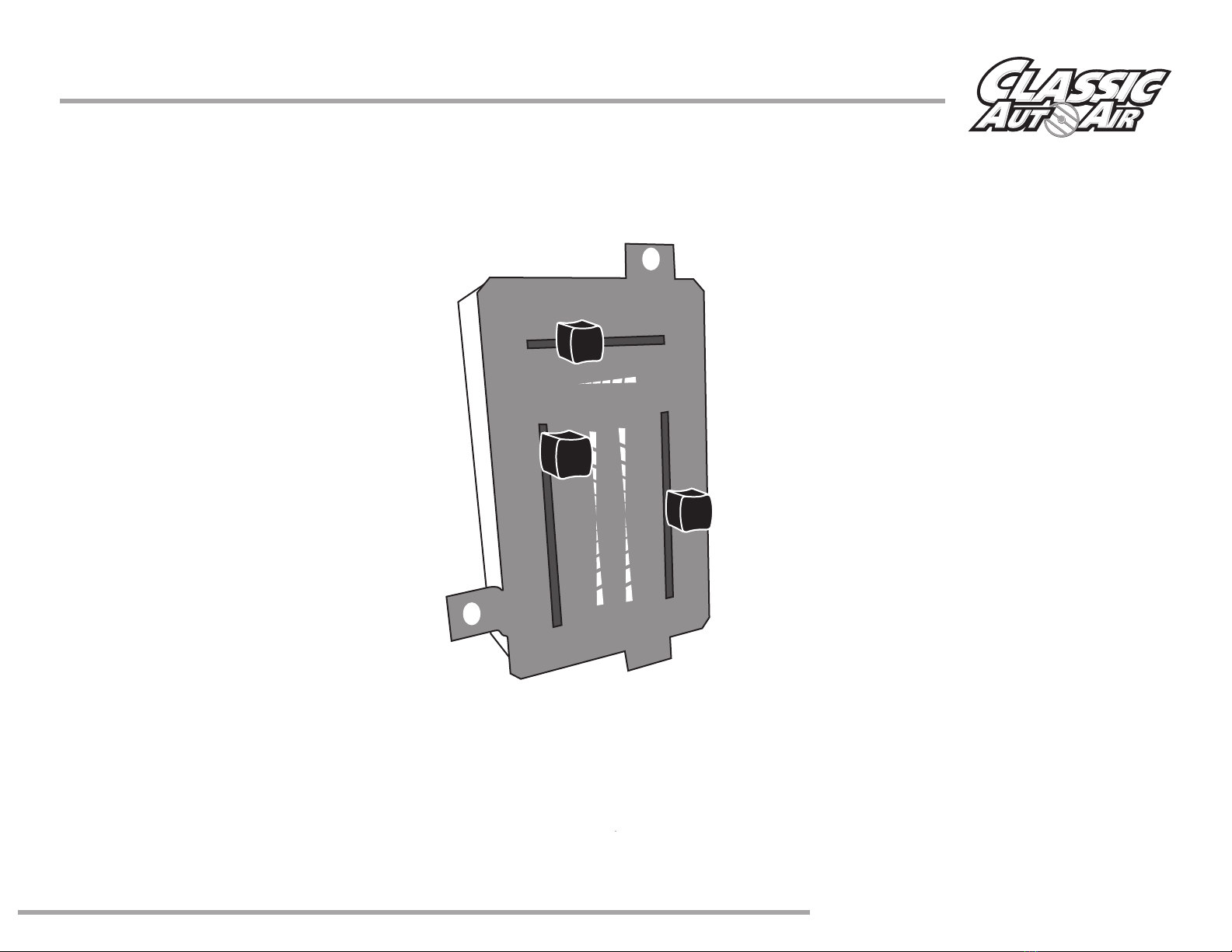
Interior Preparation
FIGURE 5
Disconnect the electrical harness at the resistor block (see Figure 5).
Remove the (4) screws that hold the console control assembly.
Remove the “Vent” knobs using an allen wrench. Retain knobs.
Remove the console cover. Retain all original hardware.
(you will need the bezel later).
CAUTION:
WHEN VEHICLE IS EQUIPPED WITH FIBER OPTICS.
CAREFULLY REMOVE THE CONSOLE COVER.
PAGE
8
www.classicautoair.com • 866.435.7801
When removing controls make certain to plug
any open vacuum source.
Remove passenger kick panel and retain
hardware, remove vacuum motor and mounting
hardware. Use existing spring to keep fresh air
door.
Factory A/C Cars
www.classicautoair.com • 866.435.7801
Interior Preparation
DISCONNECT BATTERY. (BATTERY IS LOCATED INSIDE THE CAR BEHIND THE DRIVERS
PAGE
9
Remove the (3) screws that hold the
center bezel in place. Retain bezel screws.
Remove the OEM control head,
which is held in with two screws.
Retain the OEM screws.
Locate the vacuum Tee from Bag
Kit B. Attach the red stripped, the
blue stripped and the black
vacuum source to the Tee.
Red Stripped
Blue Stripped
Vacuum
www.classicautoair.com • 866.435.7801
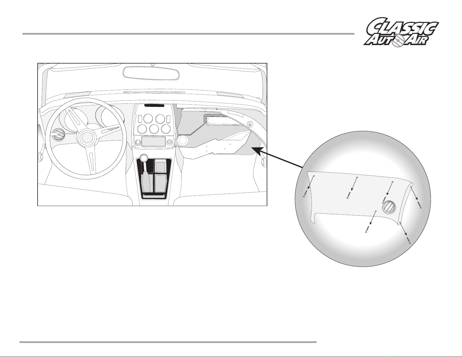
Interior Preparation
On the passenger side of the instrument panel.
Locate and remove the (5) screws that attach the cover to the car.
Retain all original hardware.
PAGE
10
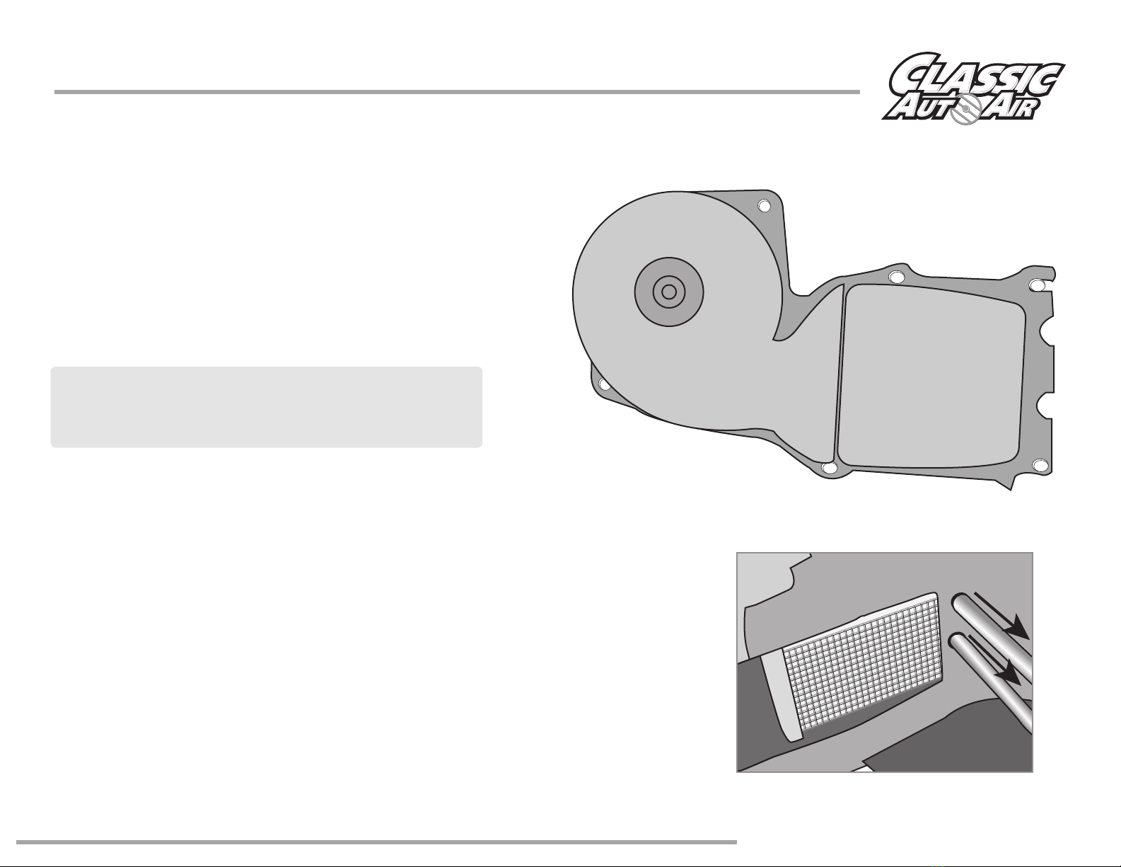
OEM Heater and Defrost System Removal
FIGURE 7
FIGURE 8
Moving to the engine compartment:
In order to remove your heater assembly it is
necessary to remove the heater case housing first.
Located on the engine side of the firewall, remove six
(6) bolts around the perimeter of the heater case
housing (see Figure 7). Remove the housing (Discard).
NOTE: To remove the two bolts at locations 1A and
6B, it may be necessary to lower the inner fender.
Retain these screws.
Drain coolant from radiator. Remove the heater
hoses from heater coil and firewall (see Figure 8).
You will also cut a power lead to the blower motor. This will not be re-used.
www.classicautoair.com • 866.435.7801
PAGE
11
1A
23
4
5
6B

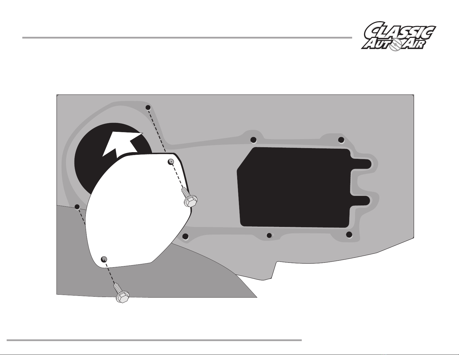
You should now be able to remove the heater assembly located behind
the dash area.
Rotate upward being careful not to drain any coolant left in the heater coil.
www.classicautoair.com • 866.435.7801
OEM Heater and Defrost System Removal, continued
PAGE
12
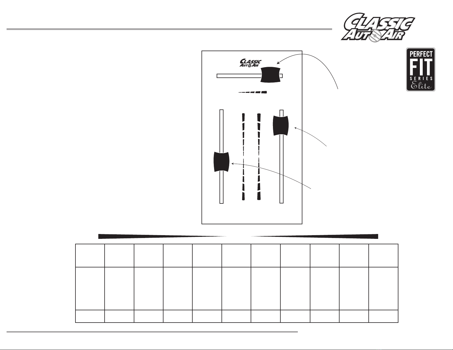
Illustrations NOT shown actual size
D.E.R. Controller, 1968-74 Corvette
PN #16-3053
DASH COLD
DEF
HOT
OFF HI
Control Box
THESE ARE THE PARTS YOU WILL FIND IN CONTROL BOX
You will use all of these parts and hardware during the next series of installation steps.
PAGE
13
www.classicautoair.com • 866.435.7801

Illustrations NOT shown actual size
Two #10 - 16 x 3/4" Tek Screws
Six #10 - 10 x 5/8" Phillips Screws
Evaporator Support Brackets
PN#0023-7
Fresh Air Inlet Block Off
PN#10-1048-2 One Male Spade Connector
THESE ARE THE PARTS YOU WILL FIND IN BAG KIT B
You will use all of these parts and hardware during the next series of installation steps.
One Flange Nut
One Air Inlet Block Off
PN#0088-9
PAGE
14
www.classicautoair.com • 866.435.7801
BAG KIT B
Two 1 1/2" Cap Plugs
One #6 - 20x3/8" Screws
One 1/4" Washer
Two 1/4 - #20 x 5/8" Bolts
3/16” Vacuum Tee
PAGE
15
Air Block Off
www.classicautoair.com • 866.435.7801
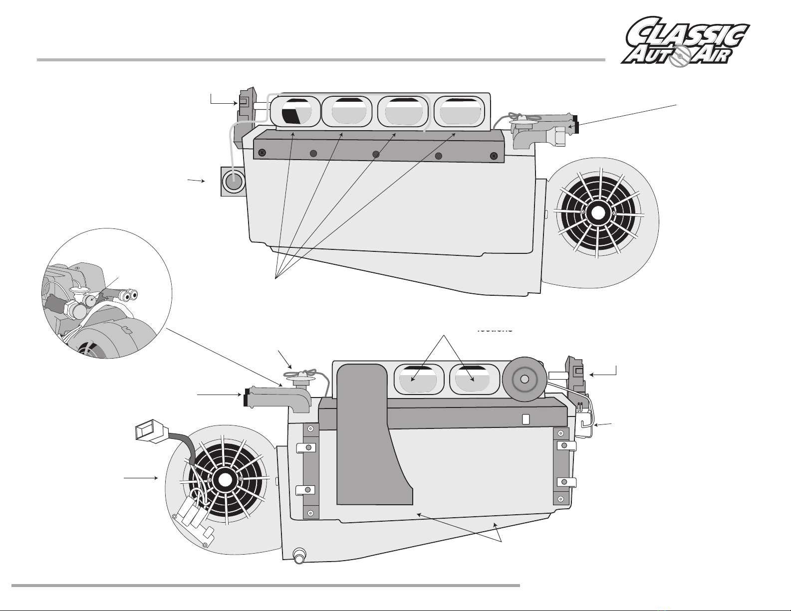
www.classicautoair.com • 866.435.7801
Familiarize yourself with the Evaporator
Dash Hose Connections
Actuator Motor
Actuator Motor
Thermostat
Expansion Valve
Heater Hose
Connections
Hose Connection
Blower Motor
Defrost Hose Connections
Heater Air Dumps
Thermostat
Liquid Pressure Hose Connection
Defrost Hose Connections

WIRING PREP •Items Needed for Bench Calibration
CLASSIC AUTO AIR
Page 17
DASH COLD
DEF
HOT
OFF HI
Locate main wiring harness from Bag Kit
FACE/FLOOR
POWER
CONTROL
WATER VALVE
DEFROST
Calibration Key
Locate ECU and Calibration Key from Bag Kit
DO NOT USE CALIBRATION KEY WITHOUT TECH SUPPORT
Locate the Controls
Locate Yellow, Orange wiring harness from Bag Kit
12V Power Source
Acquire a 12V Battery (NOT a battery charger)
Locate Evaporator Unit from Main Box Locate electronic water valve from Bag Kit
H
E
A
T
E
R
C
O
R
E
W
A
T
E
R
P
U
M
P

WIRING PREP •Wiring Preparation Steps 1 & 2
CLASSIC AUTO AIR
Page 18
1
Connect Yellow Harness into Defrost/Heat Servo Motor
Click!
2
Connect Orange Harness into water valve
Click!
H
E
A
T
E
R
C
O
R
E
W
A
T
E
R
P
U
M
P
H
E
A
T
E
R
C
O
R
E
W
A
T
E
R
P
U
M
P
FACE/FLOOR
POWER
CONTROL
WATER VALVE
DEFROST
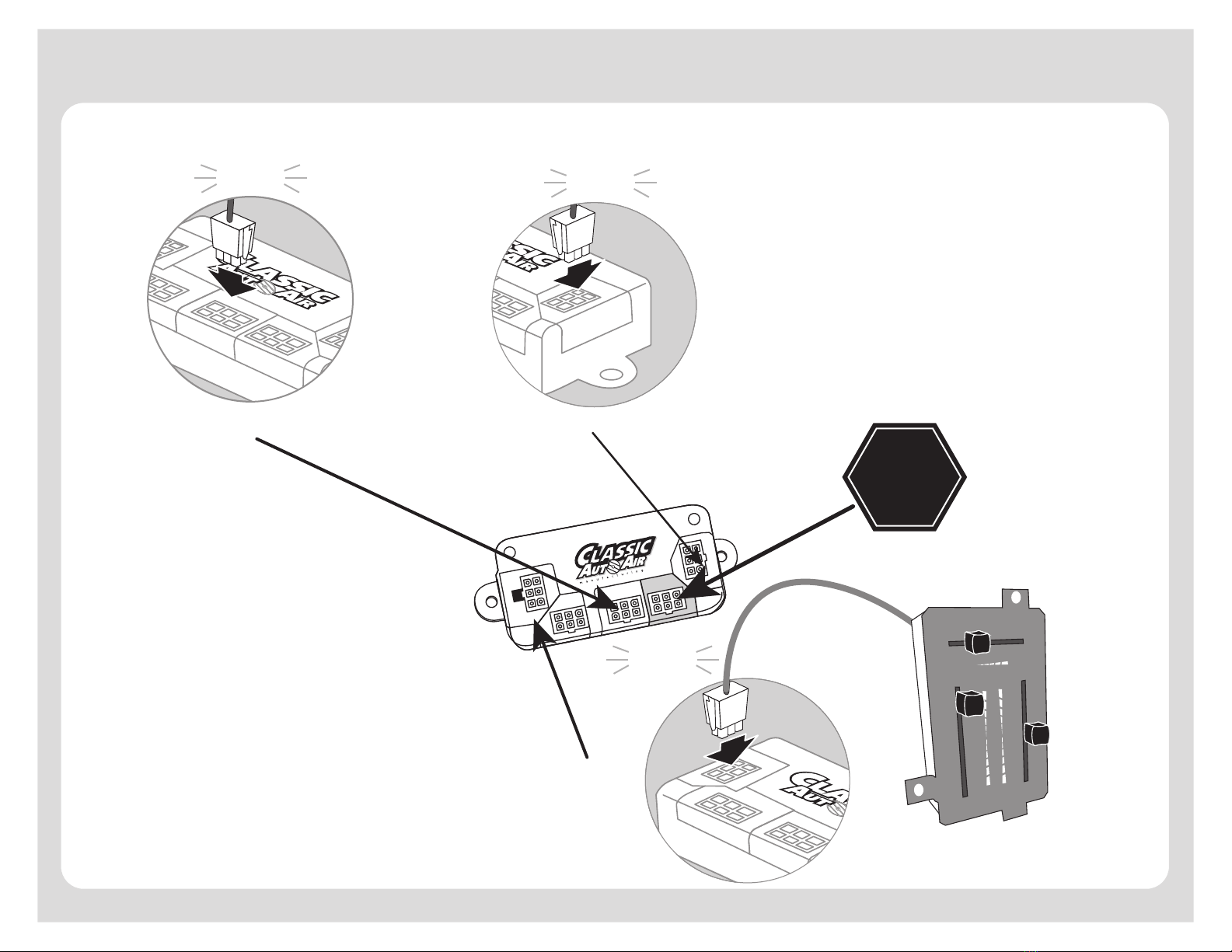
3
5
4
Connect Orange Harness into Water Valve Port on ECU
DO NOT USE
Connect Yellow Harness into Face/Floor Port on ECU
From your D.E.R.,
Connect Green Harness into
Control Port on ECU
Power
Control Water Valve
Face/Floor Defrost
Power
Control Water Valve
Face/Floor Defrost
Power
Control Water Valve
Face/Floor Defrost
Click!
Click!
Click!
DASH COLD
DEF
HOT
OFF HI
WIRING PREP •Wiring Preparation Steps 3 though 5
CLASSIC AUTO AIR
Page 19

WIRING PREP •Wiring Preparation Steps 6 through 10
CLASSIC AUTO AIR
Page 20
7
8
9
610
12V
Power
Control Water Valve
Face/Floor Defrost
Grd -
Grd
Grd
Connect both BLUE leads into thermostat
(either lead into either terminal)
Connect ground.
Connect corresponding Fan Switch
harness to the Bower Switch on Controls
Connect Power lead
to 12V.
Connect corresponding fan motor harness.
Connect ground.
Connect red tagged power harness to POWER port on ECU.
Connect ground.
Grd -Grd -
12V Power
(20 amp fuse) Grd -
(White lead is to be
connected to compressor)
Click!
Click!
Other manuals for Perfect Fit Elite Series
1
Table of contents
Other Classic AutoAir Automobile Accessories manuals


