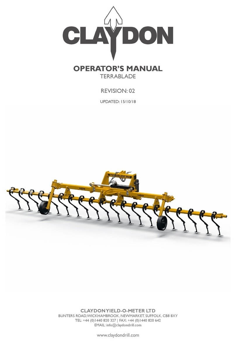
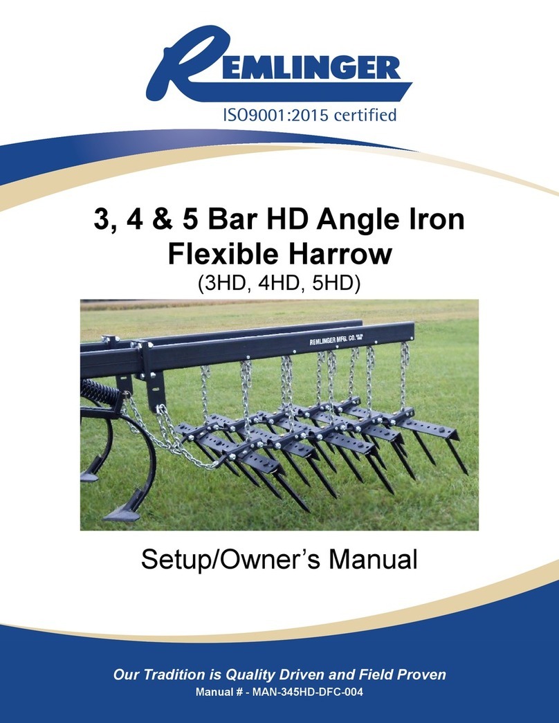
Claydon Straw Harrow - 7.5m User manual

7.5m - Straw Harrow
Contents
1.0. Straw Harrow Warranty Registration ................................................................................ 1
2.0. Safety.............................................................................................................................. 3
2.1. Warning Symbols.........................................................................................................................3
3.0. Introduction..................................................................................................................... 5
3.1. Identification of the Machine ........................................................................................................5
3.2. Warnings and Cautions................................................................................................................6
3.3. Equipment Overview....................................................................................................................6
4.0. Connecting the Straw Harrow to the Tractor..................................................................... 7
4.1. Transportation..............................................................................................................................8
5.0. Straw Harrow Set-up........................................................................................................ 9
5.1. Set Machine Level........................................................................................................................9
5.2. Working Height.............................................................................................................................9
5.3. Field Use....................................................................................................................................10
6.0. Care and Maintenance ................................................................................................... 11
6.1. Lubricating Points.......................................................................................................................11
Part's Manual
7.5m Straw Harrow Spare Parts............................................................................................ 14
Straw Harrow Front Chassis.............................................................................................................15
Wing Assembly –RH ........................................................................................................................17
Wing Assembly –LH.........................................................................................................................20
Straw Harrow Bars and Assembly - LH ............................................................................................22
Straw Harrow Bars and Assembly - RH............................................................................................23
Hydraulics –Rake Angle...................................................................................................................24
Hydraulics –Wing Folding ................................................................................................................25
Appendix A –Declaration of Conformity............................................................................... 26

7.5m - Straw Harrow
[1]
1.0. Straw Harrow Warranty Registration
In order to activate your Claydon Warranty this page must be completed and returned to:
Claydon Yield-O-Meter Ltd
Gaines Hall,
Wickhambrook,
Newmarket,
Suffolk,
CB8 8YA
Tel: +44 (0) 1440 820 327
Fax: +44 (0) 1440 820 642
IF THE REGISTRATION DOCUMENT IS NOT RETURNED THEN THE STRAW HARROW
WARRANTY WILL BE VOID
Straw Harrow Warranty Registration
NAME:
ADDRESS:
CONTACT NUMBER:
DELIVERY DATE:
SERIAL NUMBER:
PLEASE ENSURE:
The Machine is washed off upon delivery to remove any road salt.
SIGNATURE:
PLEASE RETURN WITH A COPY OF YOUR INVOICE AND THE DELIVERY NOTE.
THE HYDRAULIC FREE FLOW SERVICE MUST BE PL THE HYDRAULIC FREE
FLOW SERVICE MUST BE PLUGGED IN PRIOR TO THE DRILL BEING
OPERATED.UGGED IN PRIOR TO THE DRILL BEING OPERATED.

7.5m - Straw Harrow
[2]
Commissioning Check Sheet and Conformation Form –Straw Harrows
All points in this form must be completed on the commissioning of a new Claydon machine with the
end user. This form along with a filled in Warranty Card (located in the instruction manual) must be, fully
completed, signed by the customer and returned to: The Service Department, Claydon Yield-O-Meter
Ltd, Gaines Hall, Wickhambrook, Newmarket, Suffolk, CB8 8YA within 7 days of the commissioning of the
machine for Warranty to be valid. It is the customer’s responsibility to return these forms.
Customer Name:……………………….………………………............ Telephone Number:……………………………..
Machine serial number:………………….………………………………. Date of commissioning:……………………..
Address:…………………………………………………………………………...……………………………………………….
County:…………………………………..Country:………………………………………Postcode:…………………………
Task
Completed
The customer (and any operator of the machine) has been issued with and read the
operators manual.
Customer is aware of all transport locks on the machine and knows how to operate
them correctly.
The customer understands the correct sequence for folding and unfolding the
machine.
The customer understands how to set the machine level (front to rear).
The customer understands how to set the machine level (left to right).
The customer understands how to adjust and set the operating height of the
machine.
The customer understands how to adjust and set the operating angle of the tines.
The customer knows all the lubrication/maintenance points on the machine.
I …………………………………………. (representative name)
have on behalf of ……………………………………….(the
dealer name) commissioned the machine above to the
best of my ability and have covered all the points in this
check as a minimum.
Signed………………………………………………..
Date…………………………..
I …………………………………………(end user name) have
received the commissioning of my machine from a
qualified Claydon representative and am happy with the
competence of the representative and the level of
service I have received. All the details on this form are
correct to the best of my knowledge.
Signed…………………………………………………
Date…………………………..

7.5m - Straw Harrow
[3]
2.0. Safety
Safety stickers can be found located on your Claydon Straw Harrow at numerous locations
(Figure 1), these stickers must be observed to ensure your safety and that the machine is
operated in a safe manner.
2.1. Warning Symbols
Location of safety stickers –7.5m Straw Harrow:
Figure 1: Position of Safety stickers on 7.5m Straw Harrows
If any of the stickers become illegible or peel off, new stickers can be ordered and attached
in the appropriate position. The stickers must not be removed.
Meaning of warning symbols and caution labels:
Read the operating manual carefully.
Prior to operating the machine the manual must be read
fully and understood. Special attention should be applied
to the Warnings and Cautions section.

7.5m - Straw Harrow
[4]
Do not stand between the tractor and the machine.
Standing between tractor and the Harrow is especially
prohibited during coupling and uncoupling.
Retighten all nuts.
All nuts should be checked and retightened after a few
operating hours. Nuts may come loose due to machine
vibration.
Overhead Cables
When folding the wings watch out for overhead
electricity cables.
Proceed with care in the event of leaking hydraulic fluid.
Defective hydraulic hoses or incorrectly seated hydraulic
couplings can trigger unpredictable machine
movements and cause injury.
Keep clear of slewing range.
There is an extreme risk of injury from slewing or folding
machine parts.
Risk of crushing.
Gaps between components may become smaller or
disappear completely.
Riding on the machine is prohibited.
Serious or fatal injury can occur as a result of riding on the
machine.

7.5m - Straw Harrow
[5]
3.0. Introduction
Thank you for your purchase of a new Claydon Straw Harrow. The Claydon Straw Harrow is a
fast and low cost operation which can be used numerous times to create a micro-tilth, for
fast weed germination, hoeing out weeds, killing slugs and levelling out straw prior to drilling.
Using the Claydon Straw Harrow will result in a cost effective way of germinating weeds and
creating stale seedbeds.
The Claydon Straw Harrow will gather and carry some straw in its tines in the heavier patches,
and slowly release it out of the rear of the machine in a steady/even flow through the lighter
covered patches. By carrying a small amount of straw at each tine the Harrow acts like a
broom dragging along the ground. This broom effect destroys the delicate eggs by moving
and breaking them or exposing them to UV light at the surface.
Slugs tend to lay their eggs just below the straw layer in the dark damp atmosphere that suits
the eggs perfectly, and as a result are right next to a perfect food source (freshly germinated
seeds) when they hatch.
The purpose of this Operator's Manual is to comprehensively explain to the operator how to
set up, use and maintain the machine. It is important that the operator reads this manual
carefully to correctly set up, use and maintain the machine safely. For any further assistance
or explanation please contact Claydon Yield-O-Meter using the contact details given on the
front cover and quoting the serial number stamped on the left hand plate near where the
top link attaches.
3.1. Identification of the Machine
The Claydon Straw Harrow range offers the following specification:
Machine
Working
Width
Transport
Width
Approximate
Weight
Number of
Tines
Horse Power
Requirement
(Estimated)
7.5m
7.5m
2.85m
1400kg
60
135 HP
In addition to the machine identification plate, the serial number can also be found stamped
on the machine into the left hand main mounting beam.
Location of serial number
Detail of serial number (enhanced)
Record your serial number here: …………….………………………………………………………
You may need to quote the serial number of your machine when you order spare parts in the
future.

7.5m - Straw Harrow
[6]
3.2. Warnings and Cautions
These warnings and cautions must be observed when operating the Straw Harrow.
Observing the warning signs and other notices will serve the operators safety.
Ensure total weight of tractor/harrow combination does not exceed permitted
limits and the weight of tractor is sufficient for safe field and road use.
Do not allow anyone to stand between tractor and Harrow during
coupling/uncoupling procedures.
Ensure a safe distance from the machine is obeyed by spectators whilst the
machine is in work.
Pressurised hydraulic oil is dangerous therefore connecting and disconnecting
of the Harrow must only be undertaken with the tractors engine turned off
and the pressure in the hoses released.
Before operating the machine ensure no-one is standing within range of its
turning circle-including when the wings are unfolded.
BEWARE OF OVERHEAD OBSTRUCTIONS when the machine is folded up in the
transport position.
Ensure all bolts are retightened after the first eight hours of use.
Prior to transport ensure the hydraulic tap is in the lock position (adjacent to
the hydraulic pipes) to prevent the wings unfolding.
Persons are forbidden to ride on the machine.
Do not work underneath suspended loads; ensure adequate props are
positioned before maintenance work is carried out, preventing machine
falling under its own weight.
Take care not to trap body parts within moving or pivot points.
3.3. Equipment Overview
The terms ‘front’ ‘rear’ ‘left’ and ‘right’ in this manual refer to the machine as follows:
1. ‘Front’ indicated the three point linkage end of the machine.
2. ‘Rear’ indicates where the lights are mounted on the machine.
3. ‘Left’ indicated the left of the machine as you look at the machine from the rear.
4. ‘Right’ indicates the right of the machine as you look at the machine from the rear.
Figure 2: Straw Harrow overview

7.5m - Straw Harrow
[7]
4.0. Connecting the Straw Harrow to the Tractor
The Claydon Straw Harrow mounts to the 3 point linkage of the tractor on CATIIIN linkage
pins, you will need to use the correct size balls (not supplied) to fit the pins. The hydraulic
services should be paired together in spools for the main folding ram and the tine angle
adjustment rams (Figure 3).
Connections
Colour
1. Light cable
2. Folding ram
3. Tine angle adjustment
-
Yellow
Blue
Figure 3: Tractor connections
The following labels (Figure 4) can be found located on the front of the Straw Harrow, these
labels specify the corresponding hydraulic connections and there color coded indicators.
Folding cylinder
Tine adjustment
Figure 4: Labels for hydraulic services
Once the Straw Harrow is attached and at the correct working height, the top link should be
set at an angle in which the convergence point between the upper and lower link arms
should fall at the front axle (Figure 5). This can be achieved by altering the top link pin
attachment points on the tractor and the Harrow. This ensures stability and the mass of the
implement is used correctly.

7.5m - Straw Harrow
[8]
1. Upper link point
2. Upper hitch point
3. Lower link point
4. Lower hitch point
5. Vertical virtual hitch
point
Figure 5: Top link convergence position
4.1. Transportation
Raise the machine off the ground and fold the wings fully upright, ALWAYS FOLD THE
HARROW TINES BACK BEFORE FOLDING THE MACHINE UP, N.B. ensure sufficient clearance
is present between the rear of the Straw Harrow and the ground prior to folding. Once
folded, turn the hydraulic tap parallel to the cylinder to lock the wings in the upright position
(Figure 6). To unfold the wings turn the hydraulic tap in the opposite direction and operate
the spool valve. Never transport along public highways without isolating the folding cylinder.
Hydraulic tap to
lock folding
wings in
transport.
Figure 6: Location of wing isolation tap

7.5m - Straw Harrow
[9]
5.0. Straw Harrow Set-up
5.1. Set Machine Level
For optimal working, the Claydon Straw Harrow must be set level from front to rear on the top
link of the tractor. Failure to achieve this will result in the harrow blocking with straw in the
front if the top link is too short or in the back if the top link is too long. To confirm the Straw
Harrow has been set level, it is advised that whilst one person is operating the machine,
another person should ensure the harrow is set parallel to the ground.
5.2. Working Height
The Claydon Straw Harrow has no depth wheels and is designed to carry its own weight on
the tines. If you are finding that the Harrow is doing more work than you would like you can
more of the harrows weight on the tractors three point linkage.
The tine angle can be altered for aggressiveness from the cab with the hydraulic rake angle
adjustment. For chopped OSR or Bean stubble the rake angle can be at maximum if so
required (this position is most aggressive and moves the most soil, Figure 7). However, on
chopped Wheat or Barley stubble the tines will need to be angled back to allow the straw to
flow through the machine without blocking up (Figure 7).
Aggressive Rake Angle –OSR or Beans
Shallow Rake Angle –Wheat or Barley
Figure 7: Example of different rake angles in various crops
If you find that the tines are not at an equal angle on both sides of the machine the following
steps should be carried out:
Firstly you should operate the tine adjustment until they reach either of their maximum
stop positions; (fully forward or fully back).
Then return the tines to the required working position, the tine angles should now be
equal on both sides.
If one side of the Harrow tines seem to be always creeping back you should check that there
are no leaks in the hydraulic system.

7.5m - Straw Harrow
[10]
5.3. Field Use
For best results it is suggested that the Straw Harrow should be used at an angle of 30º to the
direction in which the field was harvested, this will ensure straw and chaff is spread evenly
across the field. If you are using a Claydon Drill after the harrowing operation it is advisable to
travel in the same direction as you are intending to drill.
Whilst in use, the Harrow should be dragging a small amount of straw along the ground and
slowly distributing it out the back of the machine. This will even out the straw and chaff layer
across the entire field (Figure 8).
Figure 8: Straw and chaff being distributed out the back of the Harrow
The Claydon Straw Harrow can be used on stubble fields where the straw has been baled, or
on OSR/Bean stubble as a method to start weeds chitting and a form of slug control. In this
scenario the tines can be set to a very aggressive angle to maximise soil movement.
You should pull the Claydon Straw Harrow as quickly as you can (within reason). From time to
time (very rarely) the Straw Harrow can catch a lump or a tramline and start to bounce, in
this scenario you should slow down or stop until the machine has settled and then carry on as
normal. To avoid this completely, it is recommended that a small amount of the Straw
Harrows weight (about 10%-20%) should be carried on the tractors 3-point linkage.
When in use the Straw Harrow should be kept on the ground at all times and not lifted up
when making headland turns. On completion of the field, ensure the harrows tines are fully
folded back before the machine is folded up.
TIP:
Rape straw should be harrowed in the morning whilst the morning dew is present and
Wheat straw should be harrowed in heat of the sun. This will ensure the correct
shattering effect is achieved.
When harrowing a field it is recommended that the operator should turn inside the
headland tramline, this will avoid pulling grass or weeds into the field.

7.5m - Straw Harrow
[11]
6.0. Care and Maintenance
The Claydon Straw Harrow requires very little maintenance in order to provide reliable
service. Prior to using the machine, the Straw Harrow should be checked for any broken tines
or hydraulic fluid leaks. Ensure all bolts are retightened after the first eight hours of use.
6.1. Lubricating Points
Lubrication should be performed using multi-purpose grease on a daily basis. An overview of
the 7.5m Straw Harrow can be seen in Figure 9, with the identification numbers
corresponding to the details of the lubrication points in Figure 10.
N.B. Lubrication should also be placed on the Harrows top link pin to prevent excessive wear
from the upper link ball at regular intervals.
Figure 9: Lubrication points

7.5m - Straw Harrow
[12]
Lubrication Points to be Greased Daily
1. Folding cylinder rod end
2. Left wing pivot pin
3. Right wing pivot pin
4. Right wing pivot pin
5. Folding ram base end
6. Left wing pivot pin
Figure 10: Details of lubrication points

7.5m - Straw Harrow
[13]
7.5m Part's Manual

7.5m - Straw Harrow
[14]
7.5m Straw Harrow Spare Parts
ITEM NO.
PART NUMBER
DESCRIPTION
QTY.
1
SHA15
Straw Harrow Front Chassis
1
2
SHA71
Wing Assembly - RH
1
3
SHA70
Wing Assembly - LH
1
4
SH0415
Clamping Plate - No Locating Holes
2
5
SH0411
Clamping Plate
2
6
HEX HEAD BOLT M16 x 200
10.9 BZP
16
7
PLAIN WASHER M16 FORM
A BZP
32
8
NYLOC NUT M16
16

7.5m - Straw Harrow
[15]
Straw Harrow Front Chassis
ITEM NO.
PART NUMBER
DESCRIPTION
QTY.
1
SHA01
HEADSTOCK W/ASSY
1
2
SHA02
BEAM ASSY RH
1
3
SHA03
BEAM ASSY LH
1
4
SHA16
Harrow Folding Ram
1
5
SH1103
Pivot Washer
2
6
SHA12
Big Folding Ram Pin
2
7
SHA11
2
8
DU808560
DU BUSH 80 X 60
8

7.5m - Straw Harrow
[16]
9
PIN32X125
32MM TOP LINK PIN
1
10
PIN36X130
36MM TOP LINK PIN
2
11
LP11X50
LINCH PIN 11 x 50
3
12
HEX HEAD BOLT M12 x
120 10.9 BZP
2
13
PLAIN WASHER M12
8
14
NYLOC NUT M12
4
15
HEX HEAD BOLT M12 x 40
10.9 BZP
2
16
MH85X320
MANUAL HOLDER
1
17
SELFDRILLHEX121
12 x 1 [5.5 x 25] Hex Head Self Tapping
Drill Screw
6
18
WASHMUDM625Z
6 x 25 BZP Mudgaurd Washer
5
19
HC14
1/4" 2 WIRE HOSE CLAMP
2
20
JB001
Junction Box - Light Units
1
21
PC8MM
P-Clip 8mm Closed Diameter
1
22
HEX HEAD BOLT M6 x 65
10.9 BZP
HEX HEAD BOLT M6 x 65 10.9 BZP
3
23
PLAIN WASHER M6
FORM A BZP
3
24
Data Plate Straw
Harrow 7.5m
Data Plate Straw Harrow 7.5m
1
25
PR 4X10.2
POP RIVET 4mm x 10 ALUMINIUM Blind
Rivet Dome
2

7.5m - Straw Harrow
[17]
Wing Assembly –RH

7.5m - Straw Harrow
[18]
ITEM NO.
PART NUMBER
DESCRIPTION
QTY.
1
SHA62
Centre Bar No Hose Clamps
2
2
SHA60
TINE SUPPORT FRAME - RH
1
3
SHA59
TINE SUPPORT FRAME - LH
1
4
PLAIN WASHER M16
FORM A BZP
36
5
NYLOC NUT M16
18
6
HEX HEAD BOLT M16
x 50 10.9 BZP
HEX HEAD SCREW M16 x 50 10.9
BZP
8
7
7.5m SH Bar 6
7.5m SH Bar 6 RH
1
8
7.5m SH Bar 7
7.5m SH Bar 7 RH Assembly
1
9
7.5m SH Bar 8
7.5m SH Bar 8 RH Assembly
1
10
7.5m SH Bar 9
7.5m SH Bar 9 RH Assembly
1
11
7.5m SH Bar 10 RH
7.5m SH Bar 10 RH Assembly
1
12
SH0412
Harrow Bar Washer
5
13
SP910_100
SPLIT PIN 10 x 100
4
14
HEX HEAD BOLT M16
x 110 10.9 BZP
10
15
PLAIN WASHER M12
FORM A BZP
16
16
NYLOC NUT M12
8
17
MB423X423RW
Marker Board 423mm x 423mm
Red & White
1
18
SHA17
Angle Adjustment Ram
1
19
SHA05
Angle Adjustment Bar
1
20
LP11X35 UH
LINCH PIN 11 x 35mm Under
Head Linch Pin
5
21
RL002
LED Bolt on Rear Light
1
22
SHA13
Small Ram Base Pin
1
23
SHA14
Small Ram Rod Pin
1
24
SHA58
Harrow Stand RH
1
25
HEX HEAD BOLT M12
x 40 10.9 BZP
8
26
PIN19x57
Pin 19mm x 57mm
5
27
PP4040
END PLUG 40 SQ.
2
Table of contents
Other Claydon Tractor Accessories manuals

