TeeJet 5000 User manual

1. GENERAL USE
2. GENERAL FUNCTIONS
3. SPRAYER
4. FERTILISER DISTRIBUTOR
5. DRILL
6. BALER
7. SLURRY SPREADER
8. OTHER IMPLEMENTS
9. DGPS FUNCTIONS
10.
11. OVERVIEW
12. FITTING INSTRUCTIONS

Contents
GENERAL USE................................................................................................................ 1.1
GENERAL FUNCTIONS .................................................................................................. 2.1
SPRAYER ........................................................................................................................ 3.1
FERTILISER DISTRIBUTOR, OTHER TYPE .................................................................. 4.1
FERTILISER DISTRIBUTOR, OTHER TYPE WITH REG.............................................. 4.13
FERTILISER DISTRIBUTOR, BØGBALLE (D, E, DZ & EX) .......................................... 4.23
FERTILISER DISTRIBUTOR, BREDAL (B2, B3, B4 & B6)............................................ 4.35
FERTILISER DISTRIBUTOR, BREDAL (HYDR. B) ....................................................... 4.47
FERTILISER DISTRIBUTOR, BREDAL (HYDR. K) ....................................................... 4.61
FERTILISER DISTRIBUTOR, BREDAL K RAMP .......................................................... 4.75
FERTILISER DISTRIBUTOR, RAUCH AERO ............................................................... 4.89
FERTILISER DISTRIBUTOR, RAUCH BETA/DELTA.................................................. 4.101
FERTILISER DISTRIBUTOR, RAUCH AXERA H ........................................................ 4.113
FERTILISER DISTRIBUTOR, REIβL ........................................................................... 4.125
SEED DRILL, OTHER TYPE ........................................................................................... 5.1
SEED DRILL, NORDSTEN ............................................................................................ 5.15
SEED DRILL, LEMKEN.................................................................................................. 5.31
SEED DRILL, SIMBA ..................................................................................................... 5.61
BALER ............................................................................................................................. 6.1
SLURRY SPREADER, OTHER TYPE ............................................................................. 7.1
SLURRY SPREADER, HYDRAULIC CONTROL........................................................... 7.15
SLURRY SPREADER, HORSCH .................................................................................. 7.27
SLURRY SPREADER, ZUNHAMMER........................................................................... 7.41
OTHER IMPLEMENT....................................................................................................... 8.1
DGPS ............................................................................................................................... 9.1
FITTING INSTRUCTIONS ............................................................................................. 12.1

INTRODUCTION
Welcome to many hours of pleasurable work with your new TeeJet 5000 Multi-
Implement Computer.
We recommend that you read at least the general information chapters in this
manual, before you start using the computer.
Please remove the implement chapters in this manual that you do not require, but
don’t throw them away, as you will need them again when you expand your TeeJet
5000 system.
We have tried to write this manual as readable as possible using as little
“computer talk” as possible.
Please read chapters 1 and 2; sit in the cab with this manual, switch the computer
on and “page” your way through the many new possibilities the TeeJet 5000
provides.
Try to learn only 1 program: i.e. the program relating to the implement to be used
first. As once you have learnt one program, you have learnt them all.
Please don’t be confused by the constantly changing pictures and text on the
screen, this will soon become second nature for you when operating the TeeJet
5000.
Be selective: avoid using too many functions to start with, i.e. “warnings”. These
functions can always be selected when, at a later date, you feel more confident
with the computer.
A TeeJet 5000 is not just a “TeeJet 5000”, but a product that is under constant
development.
The computer “version” is displayed on the screen each time the computer is
started. Please use this reference should you need to contact your local dealer.
You are always welcome to contact your local dealer with questions or
suggestions for the TeeJet 5000 plus the wide range of implement equipment
available that is always under development in close co-operation with leading
machinery manufacturers.
This manual is written so that many of the functions that are available in all of the
programs are described in chapters 1 and 2, e.g. forward speed calibration and
the task function.
TeeJet 5000 version 4.16

IMPORTANT
We have endeavoured to deliver a fault free product. To ensure optimal use of the
equipment we ask that great attention be paid when reading the manual. Please
contact your local dealer if further support is needed. Regarding responsibility for
use of the product we refer to our sales and delivery terms especially paragraph 7,
which follows:
7. Product usage.
7.1 Any use of the product is at the sole risk of the buyer. The buyer is
therefore not entitled to any form for compensation caused by, for
example, any of the following:
Disturbance to/from any electronic services or products that do not
confirm to the standards for CE marking,
Missing or poor signal coverage or a succession hereof from external
transmitters/receivers, used by the buyer,
Functional faults, which apply to or from a PC-program or PC-
equipment, not delivered by the seller,
Faults that may arise from the buyers negligence to react to
warnings and fault messages from the product, or which can be traced
to negligence and/or absent constant control of the work carried out
in comparison to the planned job.
7.2 When implementing any new equipment the buyer must take great care and
pay attention. Any doubts as to correct operation/use should result in
contacting the sellers service department.
This manual may not be altered, copied or manipulated in any way. Unoriginal
manuals can lead to operational faults damaging machines or crops as a
consequence thereof. TeeJet Technologies can therefore not be held responsible
for damages incurred, which can be traced to the use of unoriginal or manipulated
manuals. Original manuals can be requisitioned at any time from TeeJet
Technologies.
With regards
Mølhavevej 2
9440 Aabybro
Denmark
Tel. +45 9696 2500
Fax. +45 9696 2501
www.teejet.com

General use
GENERAL USE................................................................................................................ 1.2
CONSTANT KEYS ........................................................................................................... 1.3
RETURN KEY.......................................................................................................... 1.3
TRACTOR INFO KEY.............................................................................................. 1.3
CONTRAST ............................................................................................................. 1.3
MEMORY KEY......................................................................................................... 1.4
HOLD KEY............................................................................................................... 1.4
DELETE KEY........................................................................................................... 1.4
BACKGROUND LIGHT............................................................................................ 1.4
NUMERICAL KEYS ................................................................................................. 1.4

GENERAL USE TEEJET 5000 OPERATORS MANUAL
1.2
GENERAL USE
The TeeJet 5000 has been specifically developed to serve all commonly used
implements within agriculture; thus all tasks and implements can be operated and
controlled by the same monitor via sensors.
The TeeJet 5000 menu system has, in principal, been built up as a book in which
you can page through the different menus. The computer functions are divided into
programs. Each program has been “tailored” for the implement in question. The 6
function programs are:
Sprayer
Fertiliser distributor
Drill
Baler
Slurry spreader
Other implements
The functions available for each individual implement are described in each
individual chapter. The first two chapters describe the functions available for all
implements.
In the “SYSTEM” menu all sensors can be tested in “TEST INPUT” and the
outputs to valves, actuators, etc. in “TEST OUTPUT”. This is described in chapter
2.
The "SYSTEM DATA" menu has special encodements to which the operator has
no access.
The required operating language can be selected in “LANGUAGE”.
The TeeJet 5000 standard fitting kit for one tractor includes:
Junction box, trailer plug, wheel sensor, implement sensor, plus all necessary
parts for fitting.
This equipment allows forward speed, area, driven distance and time functions
to be displayed.
The system has been prepared for countless extensions. These will, however,
often depend on the tractor and implement type. TeeJet AGRO offers specially
designed fitting kits for most commonly known makes and models. Ask your dealer
or directly to TeeJet AGRO.
NOTE! Please unfold the page in chapter 11 before proceeding.

TEEJET 5000 OPERATORS MANUAL GENERAL USE
1.3
CONSTANT KEYS
RETURN KEY
The return key is used for returning to previous
displays. It takes one display picture each time the key
is pressed. The key is also used for accepting the
status screens for encoded values (see “STATUS
SCREEN”).
TRACTOR INFO KEY
By pressing this key a number of important tractor
functions can be displayed regardless of which
function has been selected.
The tractor info functions are:
FORWARD SPEED
WHEEL SLIP
DIESEL CONSUMPTION PER HOUR
WORK EFFICIENCY
AREA
REMAINING AREA
Press the “RETURN KEY” to revert to previous screen.
CONTRAST
Pressing this key allows the screen contrast (dark/light)
to be adjusted. This ensures that the information on the
screen can be seen under all conditions.
NOTE: extreme heat or cold may cause the screen to
appear black or totally blank. Using the
CONTRAST key allows for this to be
compensated for, but when the TeeJet 5000
reaches normal operating temperature the
screen will again become un-readable.
The present contrast is shown at the top of the display.
Normal contrast is 45 - 50.
Contrast + = darker display
Contrast - = brighter display
Pressing the “C” key sets the contrast to 50

GENERAL USE TEEJET 5000 OPERATORS MANUAL
1.4
MEMORY KEY
The memory keys works as a bookmark. Pressing this
key stores the currently selected screen. After moving
around through the menus simply pressing the memory
key again will return the screen to the previously
selected screen.
NOTE! The MEMORY KEY works only within one
implement at a time (e.g. sprayer).
HOLD KEY
This key has different functions depending on the
implement selected
Hold key on seed drill
Fill flow menus for sprayers
Start and stop for certain fertiliser distributors
DELETE KEY
The delete key is used together with the numerical keys
for encoding. It deletes the selected value. Also used
for zeroing the pulse counters in “TEST INPUT”.
BACKGROUND LIGHT
This key is used for switching the display light on and
off. switching the light on and off can also be done in
the CONTRAST menu.
NUMERICAL KEYS
The numerical keys are used for encoding.

General functions
GENERAL FUNCTIONS .................................................................................................. 2.2
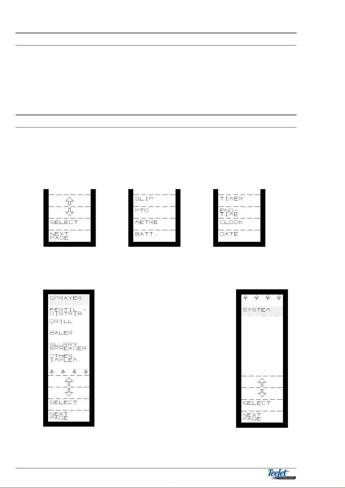
FUNCTION KEYS ............................................................................................................ 2.2
BASIC MENU........................................................................................................... 2.2
STATUS SCREEN................................................................................................... 2.3
TRACTOR FUNCTIONS.......................................................................................... 2.4
AREA FUNCTIONS ................................................................................................. 2.4
TIME FUNCTIONS .................................................................................................. 2.4
TASK FUNCTION ............................................................................................................ 2.5
TASK OPERATION ................................................................................................. 2.6
START TASK........................................................................................................... 2.7
ID NO....................................................................................................................... 2.8
STOP TASK............................................................................................................. 2.8
SEE TASK ............................................................................................................... 2.8
DELETE TASK......................................................................................................... 2.9
PRINT TASK:........................................................................................................... 2.9
PRINT ONE: ............................................................................................................ 2.9
PRINT ALL:............................................................................................................ 2.10
PRINTING TASKS VIA A PC................................................................................. 2.10
CONNECTION OF THE TEEJET 5000 TO THE PC: ............................................ 2.10
SETTING “TERMINAL” UP.................................................................................... 2.11
SETTING “HYPER TERMINAL” UP....................................................................... 2.12
RECEIVE TEXT. .................................................................................................... 2.14
EDITING THE TEXT. ............................................................................................. 2.15
DATA/DELETE............................................................................................................... 2.16
FORWARD SPEED SENSOR........................................................................................ 2.17
WHEEL TRACTOR................................................................................................ 2.17
WHEEL IMPLEMENT ............................................................................................ 2.17
RADAR .................................................................................................................. 2.17
MANUAL CALIBRATION ....................................................................................... 2.18
AUTOMATIC SPEED SENSOR CALIBRATION.................................................... 2.19
SYSTEM:........................................................................................................................ 2.20
TEST INPUT/OUTPUT .......................................................................................... 2.21
TEST INPUT/OUTPUT, SPRAYER ....................................................................... 2.22
TEST INPUT/OUTPUT, FERTILISER SPREADER ............................................... 2.23
TEST INPUT/OUTPUT, SEED DRILL ................................................................... 2.27
TEST INPUT/OUTPUT, BALER............................................................................. 2.29
TEST INPUT/OUTPUT, SLURRY SPREADER ..................................................... 2.30
TEST INPUT/OUTPUT, OTHER IMPLEMENT...................................................... 2.32
DIESEL FLOW FIGURE ........................................................................................ 2.33
SPEED SIMULATION............................................................................................ 2.33
GPS SYSTEM........................................................................................................ 2.33
SYSTEM DATA...................................................................................................... 2.33
IMPLEMENT INFO ................................................................................................ 2.33
GENERAL WARNINGS: ................................................................................................ 2.34

GENERAL FUNCTIONS TEEJET 5000 OPERATORS MANUAL
2.2
GENERAL FUNCTIONS
This chapter deals with the functions that can always be chosen no matter which
implement is used. The functions related to a certain implement will be dealt with
in the chapter on the implement in question.
The encoded values, which are conditional on several of the functions, will be
dealt with under the respective implements as each implement has specially
encoded values.
FUNCTION KEYS
Using the 4 FUNCTION KEYS and the RETURN KEY allows you to “page”
through all the functions of the computer in a clear and systematic manner.
The actual function of each of the 4 function keys is shown on the display to the
left of the key. Pressing one of the keys may change all of the keys to a new
function (see the examples below).
BASIC MENU
The display shown is the first page of
the menu system. From this screen the
first selection is made, i.e. which of the
6 implement programmes you want to
use.
Moving the cursor (the dark area) by
using the arrow keys and then pressing
the SELECT key, selects the required
implement

TEEJET 5000 OPERATORS MANUAL GENERAL FUNCTIONS
2.3
IMPORTANT! IMPORTANT! IMPORTANT!
During operation (driving in the field) with an implement and sensors selected, you
must not return to the BASIC MENU or change to another implement. If this is
attempted the TeeJet 5000 will display "MENU CHANGE PROHIBITED". This is
necessary to avoid incorrect measurements.
STATUS SCREEN
Each time the "OPERATION MENU" of an implement
is selected or you leave an encode menu the status
screen will automatically appear. All the encoded
values are displayed. Check and accept all the
values on the status screen before proceeding by
using the "RETURN KEY".
NB: Before start remember to zero all relevant
counters (area -, litre -, diesel counter etc.) in
"DATA/DELETE", if required.
You can select the following functions, no matter, which implement is
chosen: Some of the functions, such as area, will of course depend on the
related encoded values for the implement.
For some implements there are further functions, e.g. the area functions.
These special functions will be dealt with under the implement in question.

GENERAL FUNCTIONS TEEJET 5000 OPERATORS MANUAL
2.4
TRACTOR FUNCTIONS
SLIP = Wheel slip
PTO = Revolutions from the PTO
METRE = Distance travelled
BATT = Battery voltage
SLIP: Wheelslip in per cent. The relation between speed measured on a
wheel or an axle and speed measured by radar. This function is
active only if a radar is mounted and "ON" is encoded.
PTO: Revolutions per minute on the PTO. This function is active only if a
PTO sensor has been mounted.
METRE: Travelled distance measured in metres and based on chosen
speed sensor. Is started and stopped by the implement sensor or
manually by pressing "METRE". (Chosen under encode).
BATT: Battery voltage supply for the computer.
AREA FUNCTIONS
HA/H = Travelling efficiency
HA = Area
HA LEFT = Remaining area
HA/H: Travelling efficiency. The size of the area worked at the present
speed and with the present implement (working width).
HA: Area counter. Worked area in hectares since zeroing.
NB! A total counter for the area is found in "DATA/DELETE".
HA LEFT: Remaining area. Of the size of the field is encoded before start (in
"ENCODE") the remaining area can be read here.
TIME FUNCTIONS
TIMER: Working time in hours and minutes
END TIME: The time when the work will be finished.
CLOCK: Time in hours:minutes:seconds
DATE: Day:month:year

TEEJET 5000 OPERATORS MANUAL GENERAL FUNCTIONS
2.5
TIMER: Used for measuring the time spent at a certain job. The timer can
be stopped and started manually.
NB: the implement sensor does not control the timer.
END TIME: The time when the present job is expected to be finished
calculated on the present travelling efficiency and the encoded
remaining area.
CLOCK: Time shown in hours: minutes: seconds. Clock is set in
"ENCODE".
DATE: The date shown as day: month: year. Date is set in "ENCODE".
TASK FUNCTION
It is possible to record up to 50 individual tasks in the version 4 TeeJet 5000; these
50 tasks are independent of each other and can be shared between all of the
different implements.
If the task feature is not required, it is possible use the trip & total counters to
record data in the version 4 TeeJet 5000.
If the “Task Feature” is required, then a task number must be selected
before work commences. All trip counters (area, time and quantity) will be
reset automatically when a new task number is selected.
The main functions in the “Task Feature” are as follows:
Start task
Stop task
See task
Delete task
The following is also possible if you possess the correct accessories:
Print task,
Necessary accessories: TeeJet mobile printer incl. cable TeeJet no. 905-242
connected to the System A plug on the TeeJet 5000.
If the System A socket is used by other equipment use connecting cable TeeJet
no. 197-130.
Data transfer to a PC via the RS232 output,
Necessary accessories: Power supply and serial cable.
A PC with Windows 3.xx or Windows 95 is necessary to transfer data to a PC via
serial cable.

GENERAL FUNCTIONS TEEJET 5000 OPERATORS MANUAL
2.6
TASK OPERATION
Select the “Task Feature” as follows:
Pressing the bottom function key displays the
following:
The first menu picture in the task feature shows which
implement is being used and the number of tasks that
already contain data (half filled rectangle). The number
of empty tasks available in the memory are also
displayed (the empty rectangle).
Pressing the “Start Task” function key, displays the
following:

TEEJET 5000 OPERATORS MANUAL GENERAL FUNCTIONS
2.7
START TASK
Moving the cursor and using the “Start” function key
gives you the possibility to either open a task that has
already been worked on, or start a new task.
Note:
It is only possible to start/open, i.e. a sprayer task
when sprayer has been selected as the implement.
This means that only the tasks that relate to the
implement used are displayed in the “Start Task”
menu.
All trip counters (area, time and quantity) will continue from the previous values if
an existing task has been selected.
All trip counters for the task are set to zero if a new task is started.
The following is displayed after starting a task:
KEY IN ID NO.
STOP TASK
SEE TASK
DELETE TASK

GENERAL FUNCTIONS TEEJET 5000 OPERATORS MANUAL
2.8
ID NO.
Pressing the ID NO key allows the operator to encode
an ID. Number, this number could, e.g. be a number
that identifies a customer or an employee. It does not
matter when the ID number is encoded, but the task
must be started.
As the computer uses the task number for its own
reference, it is not necessary to encode an ID. Number
if this is not required.
Use the numeric keypad to encode the ID number. The
ID number can be deleted at any time by pressing the
“C” key.
Pressing the “return” key displays the previous menu.
STOP TASK
Pressing this function key will stop the present task; it is possible to open the task
again at any time as long as the task is still in the computer's memory.
NOTE: It is not possible to exit the implement menu if a task is active. The
computer displays the following message: MENU CHANGE NOT
PROHIBITED, and shows which task should be stopped before the
implement menu can be changed.
SEE TASK
Pressing the “See Task” function key displays the
picture to the left:
Move the cursor to the task to be seen and press the
“See Task” function key.
It is now possible to see the contents of the task
without having to start the task.
NOTE: All tasks that contain data can be seen
regardless of the implement selected for
operation, so it is possible to see tasks for, e.g.
slurry spreader even if the implement chosen
for operation is a sprayer.

TEEJET 5000 OPERATORS MANUAL GENERAL FUNCTIONS
2.9
DELETE TASK
Move the cursor to the task to be deleted and press the “Delete Task” function
key. The entire contents for the selected task will now be deleted.
NOTE: All tasks that contain data can be deleted regardless of the implement
selected for operation, so it is possible to delete tasks for, e.g. slurry
spreader even if the implement chosen for operation is a sprayer.
PRINT TASK:
Pressing the “Print Task” function key displays the
following:
PRINT ONE:
Move the cursor to the task to be printed and press the “Print Task” function key.
The contents of the selected task will be printed.
NOTE: All tasks that contain data can be printed regardless of the implement
selected for operation, so it is possible to print tasks for, e.g. slurry
spreader even if the implement chosen for operation is a sprayer.

GENERAL FUNCTIONS TEEJET 5000 OPERATORS MANUAL
2.10
PRINT ALL:
Pressing the “Print All” functions key prints all the tasks that contain data. Once
the computer has finished printing pressing the return key, displays the following:
Pressing the “Delete” function key will delete all tasks.
If this is not desired, pressing the “cancel”
function key will return the computer to the
previous screen
PRINTING TASKS VIA A PC
To transfer and print tasks to a PC, the follow items are required:
TeeJet 5000 PC interface, incl. Power supply, TeeJet stock number 905-168
PC with Windows 3.xx or Windows 95/98 operating software
Office printer
Windows has 2 programs that you can use for transfer and printing tasks.
“Write or Word pad” are word processing programs that come with Windows 3.xx.
or Windows 95/98.
“Terminal or Hyper Terminal” are communication programs that can, amongst
other things, be used to import text files via the PC’s serial port.
Other similar Windows programs can of course be used if this is desirable
CONNECTION OF THE TEEJET 5000 TO THE PC:
The TeeJet 5000 PC interface consists of a special serial cable, a 9 to 25 pin
adapter and a transformer to connect to the mains power supply.
The adapter that changes the 9-pin plug to a 25-pin plug is used when the PC has
a 25 pin serial port. Connect one end of the PC. Interface to the flying lead on the
TeeJet 5000, and the other end to the serial port being used on the PC. Connect
the transformer to the mains power supply.

TEEJET 5000 OPERATORS MANUAL GENERAL FUNCTIONS
2.11
SETTING “TERMINAL” UP.
Double click on the “Terminal” icon. You can find the program icons in various
places, depending on the way that Windows has been set-up. Refer to the
Windows operator manuals for further instruction.
Figure 1. Screen shot of settings/terminal preferences. (Windows Terminal)
Figure 2. Screen shot of settings/communications set-up. (Windows Terminal)
When you have finished set-up, choose “Save As” in the file menu. A dialogue box
is shown where it is possible to save the set-up to a file. The program suggests
.trm as the file type. Next time you wish to transfer data, all you have to do is open
this file and all the settings will be correct.
Choose the
Com. Port that
corresponds to
the serial port
being used

GENERAL FUNCTIONS TEEJET 5000 OPERATORS MANUAL
2.12
SETTING “HYPER TERMINAL” UP.
Click on the “Hyper Terminal” icon. You can find the program icons in various
places, depending on the way that Windows95 has been set-up. Refer to the
Windows95/98 operator manuals for further instruction. Double click on the
“Hypertrm.exe” icon.
Figure 3. Screen shot of “Hyper Terminal”
Select a name and an icon for this connection. Then choose the correct serial port
for your PC.
Figure 4 “New Connection”
Table of contents
Popular Tractor Accessories manuals by other brands

BROWNS
BROWNS BALE HANDLER Owners Illustrated Instruction Book & Parts List

SpeedEPart
SpeedEPart Agri-Fab 45-0302 owner's manual

McConnel
McConnel EZI-EDGER Operator's & parts manual

CARRE
CARRE ROTANET Instruction

GRIBALDI & SALVIA
GRIBALDI & SALVIA ROTOR R 4 204 Operator's manual

Homestead
Homestead Pinnacle HI-P-BX-60 Operator's manual