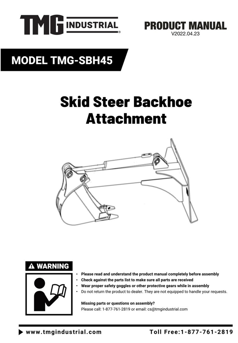
TMG TMG-SBH60 User manual

9 FT SKID STEER
SWING BACKHOE ATTACHMENT
PRODUCT MANUAL
v2023.02.07
TMG-SBH60
Please read and understand the product manual completely before assembly
Check against the parts list to make sure all parts are received
Wear proper safety goggles or other protective gears while in assembly
Do not return the product to dealer. They are not equipped to handle your requests.
Missing parts or questions on assembly?
Please call: 1-877-761-2819 or email: cs@tmgindustrial.com

IMPORTANT SAFETY INFORMATION....................................................................................................... 3
SAFETY DECAL LOCATIONS ......................................................................................................................8
PARTS DESCRIPTION AND FUCTION..................................................................................................... 10
PRODUCTS SPECIFICATIONS.................................................................................................................. 11
UNPACKING & ASSEMBLY........................................................................................................................12
CONNECTING SKID STEER LOADER...................................................................................................... 20
CHECK BEFORE OPERATING....................................................................................................................21
LUBRICATION POINTS SUMMARY..........................................................................................................22
CONTROLS.................................................................................................................................................. 23
OPERATING ESSENTIAS........................................................................................................................... 25
OPERATING FINISH....................................................................................................................................30
MAINTENANCE SCHEDULE...................................................................................................................... 31
TROUBLE SHOOTING.................................................................................................................................32
EXPLODED VIEW & PARTS LIST...............................................................................................................33
TABLE OF CONTENTS

Before operating the BACKHOE read the following safety instructions. Failure to comply with these
warnings may result in serious injury or death.
Safety Instructions
The alert symbol is used throughout this manual and this manual and on the product safety decals. This symbol indicates
attention is required and identifies hazards concerning your personal safety and the safety of others. Please follow the
recommended precautions
The safety alert symbol means...
ATTENTION! BECOME ALERT! YOUR SAFETY IS INVOLVED!
NOTICE -Indicates a situation that could result in damage to the machine or other property.
IMPORTANT SAFETY INFORMATION
WARNING
Indicates a potentially hazardous situation that, if not avoided, could result in death or serious injury, and includes
hazards that are exposed when guards are removed. It may also be used to alert against unsafe practices.
CAUTION
Indicates a potentially hazardous situation that, if not avoided, may result in minor or moderate injury. It may also
be used to alert against unsafe practices.
DANGER
Indicates an imminently hazardous situation that, if not avoided, will result in death or serious injury. This signal
word is to be limited to the most extreme situations typically for machine components which, for functional
purposes, cannot be guarded.

Safety Rules
It is the operator's responsibility to read, understand and follow ALL safety and operation instructions
In this manual. If you do not understand any part of this manual and require assistance, contact your
dealer.
The operator of this backhoe must be a responsible, physically able person familiar with machinery and trained in this
machine's operation.
Provide instructions to anyone else who is going to operate the machine. This equipment is dangerous to anyone unfamiliar
with its operation.
Review safety related items annually with all personnel who will be operating or performing maintenance.
Make sure all safety signs on the machine are understood before operating, servicing, adjusting or cleaning. Being unfamiliar
with a machine can lead to injuries.
Replace any safety sign or instruction sign that is not readable or is missing.
Never exceed the limitations of the machine. If its ability to do the job, or to do it safely is in question–STOP!
Have a first-aid kit and fire extinguisher available for use should the need arise and know how to use them.
Do not modify the equipment in any way. Unauthorized modifications may affect the integrity of the machine or the ability of
the machine to perform as designed. Modifications can impair safety or function. They can affect the life of the equipment and
void warranty.
Make sure the suspension is correctly mounted and all hardware is torqued to specifications to preventbackhoe from moving
when digging.
Never operate the backhoe without the top link installed. Make sure it is correctly adjusted to prevent the backhoe from being
pushed upward by digging force. If thebackhoe moves upward the operator can be crushed against the ROPS, FOPS, or cab.
Make sure there is adequate head room for the operator.
The skid steer loader must be equipped with a front loader and ROPS (Roll Over Protection Structure) or ROPS cab. Always
wear your seat belt when operating the skid steer loader.
Do not install backhoe if the total machine weight exceeds the ROPS weight certification.
Ensure suspension is firmly attached and all hardware is torqued to specifications to prevent backhoe frommoving when
digging.
Operating Safety
• Wear appropriate Personal Protective Equipment (PPE) when using this machine.
This includes but is not limited to:
-Hard hat
-Hearing Protection
-Protective shoes with slip resistant soles
-Protective glasses
• Always wear hearing protection if the noise in any area you work in exceeds 80 dB.
-Noise over 85 dB on a long-term basis can cause severe hearing loss.
-Exposure to noise over 90 dB over a long-term basis may cause permanent, total
hearing loss.
-Hearing loss from loud noise (from engines, chainsaws, radios, and other such sources
close to the ear) is cumulative over a lifetime, without hope of natural recovery.
• Know your controls and how to stop engine and attachment quickly in an emergency.
• Be aware of overhead hazards: branches, cables, electrical wires. Have an underground utility
locating/marking service survey the area before digging.
• Keep boom and bucket away from overhead and underground power lines and utilities. High-voltage power lines can cause
electrocution without direct contact.
• Be sure machine is properly mounted, adjusted and in good operating condition.
• Follow the Pre-operation Checklist before starting work.

• If the backhoe is powered by the tractor / skid steer hydraulic system, oil pressure and flow must beproperly matched. If a
PTO drive is used, be sure speed is correct and PTO shaft is properly shielded.
• Never operate controls from the ground. Operate only from the operator's seat to prevent unexpected boommovement that
can lead to crushing between frame members. Ensure all control levers are in neutral or off position before starting.
• Keep all bystanders in the designated safe zone during operation. Never carry, lift or move people on boom or bucket.
• Do not allow riders on this machine at any time. There is no safe place for any riders.
• Have an assistant on site to help you stay aware of situations that may be dangerous. Have the assistant stay in the
designated safe zone, wearing bright, reflective clothing.
• Inspect and secure all guards before starting.
• Before exiting the equipment, always lower the bucket to the ground and engage the parking brake.
• Operate the equipment at a speed that allows you maintain control at all times. Drive slowly over rough terrain and avoid
obstacles.
• Use extreme caution on inclines and edges where the ground could give way.
• Do not try to turn on a steep slope as this could result in a roll-over.
• Face the equipment when getting on and off.Maintain 3-point contact with steps and handrails.
• Never operate this machine under the influence ofalcohol or drugs. Consult your doctor about using this machine while
taking prescription medications.
• Do not dig under machine or stabilizers. A cave-in could result causing the machine to fall into the excavation.
• Do not exceed machine lift capacity. Overloading cancause structural damage and lead to unsafe operating conditions.
• Position backhoe so that loads extend directlybehind machine when lifting or placing heavy objects.
• Do not walk or work under a raised machine or attachment unless it is securely blocked or held in position. Donot
depend on the skid steer loader’s hydraulic system to hold the load.
• Keep stabilizers and front bucket on the ground to stabilize the machine. Skid steer loader’s wheels must be resting on the
ground during operation. Working with the wheels raised off the ground could result in serious injury or death and may cause
damage to the machine.
• Be careful operating the skid steer bucket/ loader controls if the backhoe is attached that way.It could cause damage to the
tractor subframe or skid steertieback.
• Train all new personnel and review instructions frequently with existing workers. Be certain only a properly trained and
physically able person uses the machinery. A person who has not read and understood all instructions is not qualified to use
the machine. An untrained operator can cause possible serious injury or death.
• If this machine is used by any other person, loaned or rented, it is the owner's responsibility to make certain that prior to
using, every operator:
- has read and understands the instructions in the operator's manual
- is instructed in safe and proper use of the equipment
- knows how to place the machine in a SafeCondition (see next page)
Safe Condition
Throughout this manual, we talk about a '
Safe Condition
'. What this means is parking the machine in a manner that makes it
safe to service or repair.
Place the machine in a Safe Condition before performing any service, maintenance work or storage preparation by performing
the following:
•Install boom and swing lock pins, or rest bucket on ground.
•Shut off hydraulic system.
•Set parking brake and shut off engine. Removeignition key.
•Ensure all components have stopped moving.
•Block or chock wheels.

Maintenance Safety
• Have at least two workers present when performing maintenance on this equipment. Never work alone in case an emergency
should arise.
• Keep service area clean and dry.
• Never operate the engine in a closed building. Make sure there is plenty of ventilation. Exhaust fumes can cause asphyxiation.
• Never work under unsupported equipment.
• Use only genuine OEM replacement parts. The manufacturer is not responsible for injuries or damage caused by the use of
non-approved parts oraccessories.
• Make sure all safety shields and devices are re-installed when a maintenance or service procedure is finished.
• Do not use gasoline or diesel fuel when cleaning any parts. Use a regular cleanser.
• Use proper tools that are in good condition. Make sure the procedure is understood before performing any service work.
Hydraulic System Safety
• Make sure that all the components in the hydraulic system are kept clean and in good condition.
• Make sure all components are tight, and that lines, hoses and couplings are not damaged before
applying pressure to the system.
• Do not use your hand to check for hydraulic oil leaks. Hydraulic fluid escaping under pressure
canpenetrate the skin causing serious injury. Use a piece of cardboard instead.
• Wear proper hand and eyeprotection when searching for a high-pressure hydraulic leak.
• Seek medical attention immediately if injured by a concentrated high-pressure stream of
hydraulicfluid. Serious infection or toxic reaction can develop from hydraulic fluid piercing the
skin surface.
• Do not attempt any makeshift repairs to the hydraulic lines, fittings or hoses by using tape, clamps or cements. Doing so can
cause sudden failure and create a hazardous and unsafe condition.
• Relieve pressure on the hydraulic system beforeworking it. The hydraulic system operates under extremely high pressure.
• Replace any hydraulic hose immediately that showssigns of swelling, wear, leaks, or damage before it bursts.
• Do not bend or strike high-pressure lines, tubes orhoses, or reinstall them in a bent or damaged condition.
• Check to make sure hydraulic hoses are not worn or damaged, and are routed to avoid chafing.
• Never adjust a pressure relief valve or otherpressure- limiting device to a higher pressure than specified.
Safe Zone
For safety of others during operation, set up a Work Zone around the machine. Mark the area with safety cones. Outside of that
would be considered a designated Safe Zone for other workers or bystanders.
Always know where all workers and bystanders are when operating the backhoe. Have them stay outside of the work zone in
the designated Safe Zone. They should only enter the work zone when:
–The person has made eye contact with and signaled the backhoe operator.
–The backhoe is in transport position or backhoe bucket is resting on the ground.
–The engine is shut off.

Work Zone
Establish a Work Zone perimeter the length of maximum boom reach and swing arc. Mark an additional area at least 3 ft (1 m)
around the stabilizers.
While using the backhoe, always be aware of bystanders in the area. A swinging boom can create a collision hazard to workers
or bystanders. Injury may occur from heavy material falling or dropping from the bucket.
Fig. 1 – Establish work zone perimeter
1. Designated Safe Zone
2. Work Zone
3. Boom Swing Arc
4. Safety Cones
Safety within your work zone
The safest place for the operator is in the operator’s seat.
Always operate the backhoe controls from the operator’s seat.
Always be aware of the position of the boom and material being handled.
Be aware of bystanders and workers when lowering stabilizers. Make sure they are in the safe zone where they cannot be
injured.
Always be aware of hazards such as:
Underground utilities
Tree roots
Structures close to the excavation site
Excavating on a slope
Excavating too close to the stabilizers
Modify your work zone to account for overhead hazards:
Telephone lines
Tree branches
Roof overhang
Wash lines, ropes or cables
Power lines—maintain a 20 ft (6 m) distance. Electrocution can occur without direct contact (arcing).

The safety decals and their positions are shown on the illustration below. Good safety requires that you familiarize yourself with
the various safety decals, the type of warning and the area or specific function related to that area that requires your SAFETY
AWARENESS.
SAFETY DECAL LOCATIONS
7
7
7
3
1
4
8
7
7
7
5
2
6

Warning Decals
(4)
(5)
(6)
(8)
(7)
(1)
(2)
(3)

1.Console assembly: Control machine
2.Boom assembly: The arm that performs the digging action
3.Seat assembly: Sit on the seat when operating the machine
4.Skid steer hitch assembly: Connecting Skid steer loader and Backhoe
5.Steering assembly: The left and right digging angle of the boom is adjusted by the hydraulic device
6.Base assembly: Base to support the machine
7.Outrigger assembly: Legs to adjust machine height
8.Bucket assembly: Bucket A barrel-shaped member used for digging loose materials such as soil, sand,
gravel, and construction waste
PARTS DESCRIPTION AND FUCTION
1. Console assembly
2. Boom assembly
5. Steering assembly
6.Base assembly
7. Outrigger assembly
8. Bucket assembly
4.Skid steer hitch
assembly
3.Seat assembly

Specifications
TMG-SBH60
A
Digging Depth(2 ft. flat bottom)
9’
B
Overall Operating Height(fully raised)
123”
C
Reach from Swing POST
129”
D
Loading Height(bucket at 60°rotation)
84”
Dipper Boom Digging Force
2200 lbs
E
Transport Height(with boom fully retracted)
80”
Transport Width(with stabilizers up)
58”
F
Transport Length
72”
G
Ground Clearance
10-12”
Swing Arc
180°
J
Stabilizer Spread (Spread)
89”
K
Stabilizer Spread (Transport)
58”
Bucket Digging force (lbs)
3300
Operating Pressure (psi)
2320
Recommended Skid Steer Loader (HP0
30-100
PRODUCTS SPECIFICATIONS

1. After unpacking, check the following components
The parts marked with numbers in the figure are the parts that need to be assembled.
*. All numbers are not part numbers in the drawings. For correct part numbers, see explosive diagram.
UNPACKING & ASSEMBLY
1
2
3
4
5
6
7
8
9
10
11
12
13
14
15
16
17
18
20
19
21
22

NO.
DESCRIPTION
QTY
NO.
DESCRIPTION
QTY
1
Base assembly
1
12
Outrigger cylinder pin Ø20x133
4
2
Small boom assembly
1
13
Plain washer Ø20
4
3
Seat components
1
14
Cotter pin 4x32
4
4
Skid steer loader hitch assembly
1
15
Pin shaft Ø30x181
1
5
Stabilizer legs assembly
2
16
Pin shaft Ø25x137
1
6
Fully threaded hex bolts M14x45
8
17
Fully threaded hex bolts M6x50
1
7
Plain washer Ø14
16
18
Fully threaded hex bolts M6x60
1
8
Non-metallic insert hex lock nuts M12
8
19
Non-metallic insert hex lock nuts M6
2
9
Fully threaded hex bolts M12x45
4
20
Pin welding 142
1
10
Plain washer Ø12
8
21
Swivel joint pin
1
11
Non-metallic insert hex lock nuts M12
4
22
R pin
1
* All numbers are not part numbers in the drawings. For correct part numbers, see explosive diagram.
After the parts are confirmed to be correct and the tools for installation are ready, start the assembly. The specific operation
steps are described below.
TOOLS FOR INSTALLATION
NO
DESCRIPTION
SPECIFICATION
CONDITIONS OF USE
QTY
1
Open End Wrench
10/13/18/21/30
M6, M8, M12, M14, M20 bolt fastening
2
2
Air Impact Wrench
1280t
Match the corresponding sleeve instead of the wrench to
tighten the bolt
1
3
Hammer
1
4
Torque Wrench
10-220N·m
Measuring torque
1

2. Install the Stabilizer Legs Assembly
Installation steps:
Place the stabilizer legs assembly (5) at the position shown in the figure above, align it with the installation hole on the base
assembly (1), pass through the pin shaft Ø20x133 (A14), and install the washer 20 (A13), and the cotter pin 4x32 (A12) , the left
and right outriggers are installed in the same way.
Importance: All bolts are locked in place without shaking.
WARNING: Once the assembly bolts are not fastened in place, there will be abnormal noises when the machine is
working.
PART NO.
DESCRIPTION
QTY
1
Base assembly
1
5
Stabilizer legs assembly
1
A12
Cotter pin 4x32
4
A13
Flat washer Ø20
8
A14
Outrigger cylinder pin Ø20x133
4
5
A14
A14
A12
A13
1
5

3. Install the skid steer loader hitch assembly
Installation steps:
Align the skid steer loader hitch assembly(7) with the 8 mounting holes on the base assembly , and install the full-threaded
hexagon bolt (G4), plain washer (G2), non-metallic insert hexagon lock nut (G1) in sequence and To lock it, add a flat washer (G2)
on the nut side and on the bolt side.
Importance: All bolts are locked in place without shaking.
WARNING:Once the assembly bolts are not fastened in place, there will be abnormal noises when the machine is
working.
PART NO.
DESCRIPTION
QTY
G1
Non-metallic insert hex lock nuts M14
8
G2
Plain washer Ø20
16
G4
Fully threaded hex bolts M14×45
8
7
Skid steer loader hitch assembly
1
G1
G2
G2
G4
7

4. Install the seat assembly
Installation steps:
Align the seat assembly (1) with the 4 mounting holes on the the base assembly, and install the full-threaded hexagon bolt (A6),
plain washer (A7), non-metallic insert hexagon lock nut (A8), taking care to tighten the bolts after all components are installed.
Importance: All bolts are locked in place without shaking.
WARNING: Once the assembly bolts are not fastened in place, there will be abnormal noises when the machine is
working.
PART NO.
DESCRIPTION
QTY
1
Seat assembly
1
A6
Fully threaded hex bolts M12x45
4
A7
Plain washer Ø12
8
A8
Non-metallic insert hex lock nuts M12
4
A6-A7-A8
1

5. Install small boom assembly
Installation steps:
1. Align the small boom assembly (4) with the mounting hole on the base assembly as shown in the above figure, penetrate
the pin shaft Ø30x181 (D9), install the bolt M6×60 (D8), and the nut M6 (D3) to lock and fix it.
2. Connect the upper oil cylinder and the small boom assembly in series, penetrate the pin shaft Ø25x137 (D26) of the grease
fitting, install the bolt M6×50 (D25), and the nut M6 (D3) to lock and fix it.
Importance: All bolts are locked in place without shaking.
WARNING: Once the assembly bolts are not fastened in place, there will be abnormal noises when the machine is
working.
PART NO.
DESCRIPTION
QTY
4
Small boom assembly
1
D3
Non-metallic insert hex lock nuts M6
2
D8
Fully threaded hex bolts M6x60
1
D9
Pin shaft Ø30x181
1
D25
Fully threaded hex bolts M6x50
1
D26
Pin shaft Ø25x137
1
4
D25
D26
D3
D3
D8
D9

6. Install and connection hydraulic tubing
E3
E16
D23
D24
E3
E1
H2
D27
D13

Connection steps:
As shown in the figure above, there are still 6 oil pipes that need to be connected. One side of these 6 oil pipes has been
connected to the multi-way valve, and the other side needs to be connected to the oil cylinder. The product number is marked on
the oil pipe joint. The oil pipe is connected to the corresponding oil cylinder joint according to the product number shown in the
figure above.
1. Bucket cylinder oil outlet pipe (D23)is connected with the outlet nozzle of the bucket cylinder (D27) on the small boom
assembly (D13). Bucket cylinder oil inlet pipe (D24) is connected with the inlet nozzle of the bucket cylinder (D27) on the small
boom assembly (D13).
2. Right outrigger cylinder oil inlet pipe (E1)and oil inlet pipe of left outrigger oil cylinder (E16) are connected with the intlet nozzle
of the outrigger cylinder (E2) on the strut weldment (E5). Outrigger cylinder oil outlet pipes (E3) are connected with the outlet
nozzle of the outrigger cylinder (E2) on the strut weldment (E5).
Installation steps:
There are two hydraulic tubing installations, one end connected to the flow control valve, the other end connected to the hydraulic
output of the tractor when in using. Now connect one end of the flow control valve.
1. Install one hydraulic tubing to tee joint (H19) connector of flow control valve body (H6).
2. Install other hydraulic tubing to pump suction fitting (H3) connector of flow control valve body (H6).
WARNING: All tubing joints must be tightened, otherwise there will be oil leakage, and the machine operation cannot
achieve the effect.
PART NO.
DESCRIPTION
QTY
H2
Flow control valve connecting oil pipe 1/2”(ID)X78”, 1/2 NPT fitting
2

1. About the backhoe attachment
The backhoe attachment is intended for use in earth digging. The primary use of the backhoe attachment includes digging, land
clearing, landscaping, demolition, construction, and grounds maintenance. Use of this equipment in any other manner is
considered to be contrary to the intended use of the attachment.
2. Attaching the Backhoe to the Skid Steer Loader
NOTE: Before attempting to attach the backhoe to the skid steer loader, verify that all hydraulic couplings are compatible.
WARNING – Improper attachment to the skid steer loader may cause personal injury.
CAUTION – All hydraulic connections must be clean and free of debris before making any connection.
1. Place the backhoe attachment on a level surface.
2. Position and align the skid steer loader to the rear of the attachment, within
proximity of the front of the skid steer loader.
3. Insert and connect the skid steer loader into the attachment.
- Slowly position your skid steer loader towards the rear of the backhoe.
- Slowly insert the top edge of your quick attach into the top rail of the backhoe from
underneath.
- As the top of the quick attach aligns into the backhoe, slowly roll your quick attach
back towards the machine until the entire quick attach locks into the mount. Using
either your power attach or manual levers, lock the backhoe in place.
4. Connect the hydraulic lines from the attachment to the skid steer loader.
(See page 46 of the manual for the specific connection method)
5. Close latches (or other locking mechanism) to secure the attachment to the skid steer
loader.
6. Using the skid steer loader, raise the attachment and move the attachment to ensure
hydraulic lines are clear of air and operate properly.
CAUTION – Hydraulics should operate in an even and smooth manner. Hydraulic
movement that is not even and smooth may indicate that air is in the hydraulic lines.
7. Lower the attachment to ground level.
8. Inspect that the attachment is mounted properly and securely. If the attachment
does not meet this requirement, follow the instructions to remove the backhoe
and re-attach using the instructions above.
3. Removing the Backhoe from the Carrier Machine
WARNING –Improper disconnection may result person injury or damage to the
attachment and carrier machine.
CAUTION –All hydraulic connections must be clean and free of debris before
disconnection.
1. Using the carrier machine, lower the attachment to the ground.
2. To prevent contamination, remove any dirt and debris from the couplings. Disconnect the hydraulic connection between the
attachment and the carrier machine.
NOTE: Hydraulic connections must be disconnected before disengaging latches to prevent damage to the carrier machine or the
attachment.
3. Disengage the carrier machine latches (or other locking mechanisms) from theattachment.
4. Move the carrier machine from the attachment.
CONNECTING SKID STEER LOADER
Table of contents
Other TMG Tractor Accessories manuals