Clayton LPS User manual

Lithium Power Supply User Manual
Document rev: 01.14
Firmware rev: 02:02:01
Date: 16-11-2016
Lithium Power Supply

Lithium Power Supply User Manual
!
Page 2
!
!
!
1. Safety Instructions
The Lithium Power Supply (LPS) is classified as Class 9 hazardous material UN3480, a power source with
high energy density and dangerous materials in a closed metal case!
Installation must strictly follow the national safety regulations in compliance with the enclosure, installation,
creepage, clearance, casualty, markings, and segregation requirements of the end-use application.
Installation must be performed by professional installers only. Switch off the system and check for
hazardous voltages before altering any connection!
The Lithium Power Supply must be handled only by qualified and trained personnel.
The lowest protection degree of specific parts of the LPS is IP21. Ensure that the installation of the Lithium
Power Supply is in accordance with IP21 requirements.
This is a Class I product. Only connect 230VAC In from a source that is connected to electrical earth,
including any extension cords between the source and the unit.
Especially keep these rules:
• Do not open the Lithium Power Supply.
• Do not discharge a new Lithium Power Supply before it has been fully charged first.
• Charge only within the specified limits.
• Do not mount the Lithium Power Supply upside down or on the sides.
• Check if the Lithium Power Supply has been damaged during transport.
• Do not put Lithium Power Supplies in serial or parallel.
Dangers involved in case of fire:
• Danger of dust particle explosions
• Decomposition through fire or heat under development of toxic and cauterizing gases
• Combustion gasses which strongly irritate eyes and respiratory organs
General actions to be taken by the driver if these dangers occur:
• Turn of the engine
• Put a warning signal on the road to warn others
• Inform others about the danger and direct them to stand away from the wind direction
• Call the police and fire department immediately and inform that lithium batteries (UN3480) is on
board
Instruction for fire extinguishing:
• Extinguish with water, if possible cover lithium power supply completely in water
• Extinguishing with water will produce fluoride, phosphate, fluoride-oxide and carbon-oxide.
• Alternatively extinguish with a CO2extinguisher.
Note: when put to storage the battery must be fully charged and must be recharged again every 6 months.
NON-SPILLABLE
LI-ION BATTERY

Lithium Power Supply User Manual
!
Page 3
!
!
!

Lithium Power Supply User Manual
!
Page 4
!
!
!
Table of Contents
1.#Safety#Instructions#...................................................................................................................#2!
2.#General#information#................................................................................................................#5!
2.1.#Transport#........................................................................................................................................#5!
2.2.#Disposal#..........................................................................................................................................#5!
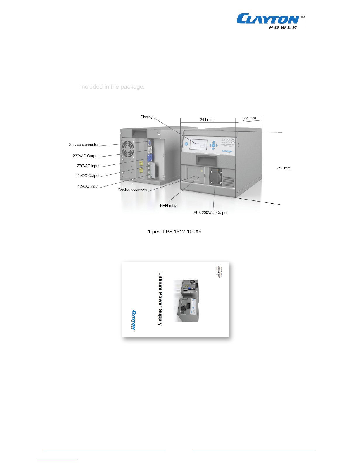
3.#LPS1512=100Ah#Box#.................................................................................................................#6!
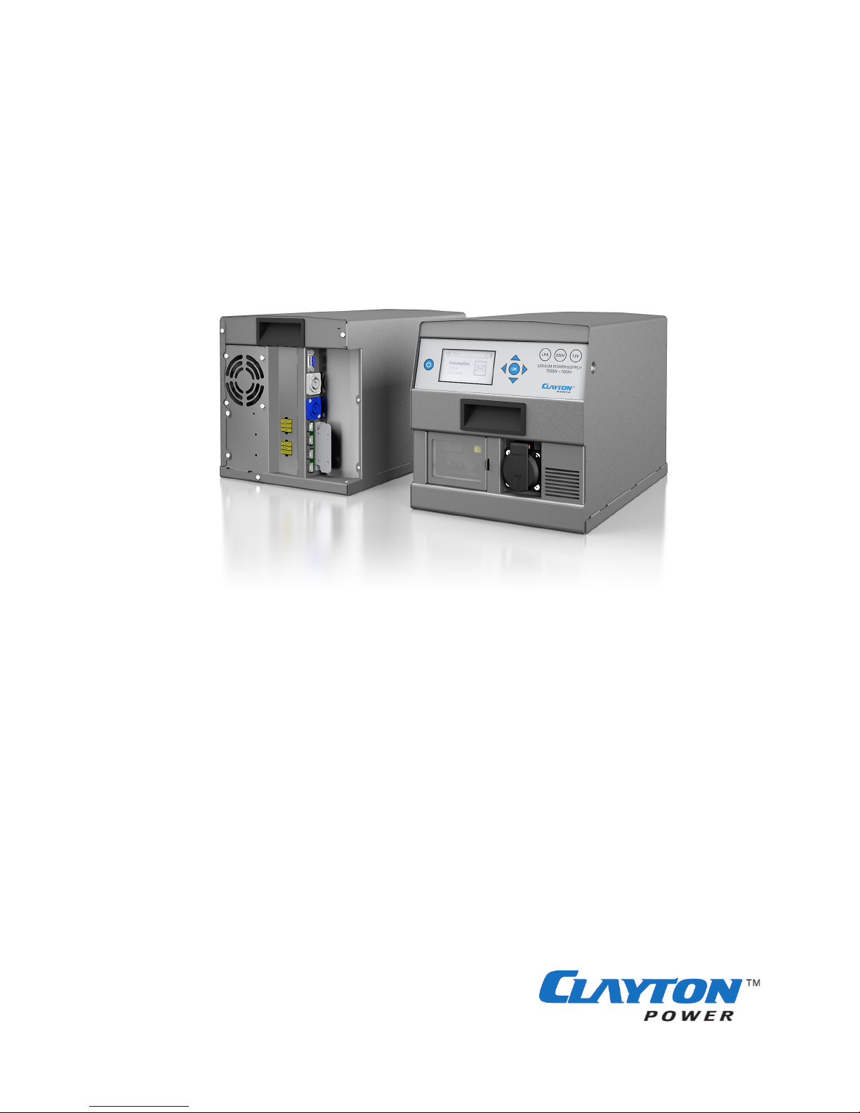
4.#Lithium#Power#Supply#=#General#parameters#............................................................................#8!
5.#Physical#dimensions#and#mounting#overview#.........................................................................#10!
6.#General#Instructions#..............................................................................................................#12!
6.1.#Installation#/#Use#of#230VAC#Input#................................................................................................#12!
6.2.#Installation#/#Use#of#230VAC#Output#..............................................................................................#13!
6.3.#Neutrik#connector#assembly#(230VAC#In/Out)#...............................................................................#14!
6.4.#Use#of#12VDC#Input#.......................................................................................................................#15!
6.5.#Use#of#12VDC#Output#....................................................................................................................#16!
6.6.#Anderson#connector#assembly#(12VDC#In/Out)#..............................................................................#16!
6.7.#Use#of#starter#help#(extra)#.............................................................................................................#17!
6.8.#Data#connector#details#..................................................................................................................#18!
7.#Operations#............................................................................................................................#19!
7.1.#Power#On/Off#...............................................................................................................................#19!
7.2.#Icon#description#............................................................................................................................#20!
7.3.#Menu#overview#.............................................................................................................................#21!
7.4.#Functionality#/#Menu#description#..................................................................................................#22!
7.5.#230VAC#Output#.............................................................................................................................#22!
7.6.#230VAC#Charging#...........................................................................................................................#24!
7.7.#12VDC#Output#...............................................................................................................................#25!
7.8.#12VDC#Charging#............................................................................................................................#26!
7.9.#General#.........................................................................................................................................#26!
8.#Failure#description#.................................................................................................................#28!
9.#Additional#information#..........................................................................................................#30!
10.#Warranty#.............................................................................................................................#31!

Lithium Power Supply User Manual
!
Page 5
!
!
!
2. General information
When the LPS is not used for longer periods of time it must be stored fully charged and recharged every 6
months
ATTENTION: Read the safety instructions before installing the Lithium Power Supply.
ATTENTION: When installing the lithium Power Supply, do not mount it upside down or on the sides. Do not
cover or block the fan or the air inlet to insure the battery does not overheat.
Mounting holes are for pre-fixation, suitable fixation has to be added.
ATTENTION: Do not connect the Lithium Power Supply in series or parallel.
ATTENTION: Make sure the Lithium Power Supply is powered down before starting the installation
The LPS is designed for indoor, household and industrial use.
2.1. Transport
The Lithium Power Supply is classified as Class 9 hazardous material UN3480 and tested according to
UN 38.3. Transport of the Lithium Power Supply must always be in original certified packaging.
The transport of Lithium Power Supply must only be handled by trained people in accordance to ADR, RID
and IMDG. For transport by air (IATA) the packaging has to be in accordance to P965, here the original
packaging complies.
For shipment of defect batteries, contact your retailer for further information.
2.2. Disposal
Batteries marked with the recycling symbol must be processed via a recognized recycling agency. By
agreement, they may be returned to the manufacturer. Batteries must not be mixed with domestic or
industrial waste.
NON-
SPILLABLE
LI-ION
BATTERY

Lithium Power Supply User Manual
!
Page 6
!
!
!
3. LPS1512-100Ah Box
Included in the box:
1 pcs. Manual!

Lithium Power Supply User Manual
!
Page 7
!
!
!
4 pcs. M3 screws!4 pcs. Anderson SB50 pins!
1 pcs. Anderson DC Output connector!1 pcs. Anderson DC Input connector!
1 pcs. Neutrik Input connector!1 pcs. Neutrik Output connector!

Lithium Power Supply User Manual
!
Page 8
!
!
!
4. Lithium Power Supply - General parameters
Table 1
Battery type
100Ah-12V (LiFePO4)
Battery capacity
100Ah (1320Whr)
Available capacity
80Ah (1050Whr)
AC Input Voltage
207 VAC – 253 VAC
AC Input frequency
45 Hz – 65 Hz
AC Input power (Charge power)
1000 W (4,5A)
AC Output voltage
230 VAC pure sine
AC Output frequency
50 Hz
AC Output power – Continuously
1300 Wrms (6A)
AC Output power – 15 min
1500 Wrms (6,5A)
AC Output current Continuously
(with 230VAC input connected)
1800W (8A) / Socket
(Total max 2300W (10A))
AC Output power peak (10sec)
2500 Wrms
DC Input voltage
12 - 15 VDC
DC Input continuous current
< 50 A
DC Output Voltage
13,2 VDC (9,2 - 15 VDC)
DC Output continuous current
60 ADC
DC Output Max Impulse current
20 min
70 A
1 min
100 A
10 Sec
150 A
Operating temperature (Output will be limited below 0°C)
-20°C~50°C
Cooling
Forced air (fan)
Self-discharge rate per month (Sleep mode)
< 3%
Operating mode self consumption (Only DC Output active)
5 W
Operating mode self consumption (Inverter and DC Output active
22 W
Sleep mode consumption
< 25 mW
Connection 230VAC
Neutrik and Schuko
Connection 12VDC
Anderson SB50
IP rating
IP21
Product Weight
28 kg
Product dimensions in mm (H x W x L)
250 x 244 x 390
Package weight
32 kg
Package dimensions in mm (H x W x L)
350 x 355 x 495

Lithium Power Supply User Manual
!
Page 9
!
!
!
Table 2
Protection Class
Class I (Do only connect to a Residual-current device (RCD) protected source)
Certifications
•2014/35/EU (Low voltage directive)
EN 62368-1: 2014 (Safety, Information technology equipment)
•2014/30/EU (EMC directive);
EN 61000-6-3: 2007 + A1:2011 Emission household
equipment
EN 61000-6-2: 2005 Immunity industrial
Safety protections
•230vac Input protected by 10AT fuse (Not replaceable)
•230vac Output Protected by 2 x 8A fuse (Resetable)
•DC Input Protected by 3 x 40A ATO fuses (replaceable)
•DC Output Protected by 3 x 40A ATO fuses (replaceable)
•Lithium battery protected by fuse (Not replaceable)
•L/N relay hazard is hardware protected.
•PE/N relay hazard is hardware protected.
Additional
protections
230vac AC Output protections
•Overload
•Short circuit
230vac AC Input protections
•Over / Under voltage
•Frequency
•Controlled charge levels
DC Input
•Over / Under voltage
•Overload
•Controlled charge levels
DC Output
•Overload
•Controlled charge levels (reverse on output)
Internal Lithium battery protections
•Over charge
•Deep discharge
•Temperature
•Overload

Lithium Power Supply User Manual
!
Page 10
!
!
!
5. Physical dimensions and mounting overview
ATTENTION: Mount the LPS topside up, never upside down or on the side.
ATTENTION: The LPS has forced air cooling. Make sure air can flow freely around the unit.
The LPS has four M5 mounting holes in the bottom as shown in figure 1.
Figure 1
244.00
386.00
25.00
25.00194.00
25.00
194.00
303.00
4 x M5

Lithium Power Supply User Manual
!
Page 11
!
!
!
Figure 2
Figure 3
390.00
250.00
244.00
250.00
250.00
244.00
Data Connector!
230VAC In!
230VAC Out!
12VDC Out!
12VDC In!
390.00
250.00
244.00
250.00
250.00
244.00
230VAC Out!
RCD!

Lithium Power Supply User Manual
!
Page 12
!
!
!
6. General Instructions
ATTENTION: Before installing, make sure that all appliances are turned off.
When installing the LPS the following connections can be used.
- 230VAC Input for charging from external mains plug (Blue Neutrik. Assembly described in section 6.3)
- 230VAC output to power 230vac equipment (Grey Neutrik. Assembly described in section 6.3)
- 12VDC Input for charging from the car generator (12VDC input, Grey Anderson SB50. Assembly
described in section 6.6)
- 12VDC output to power 12VDC equipment (12VDC output, Red Anderson SB50. Assembly described in
section 6.6)
6.1. Installation / Use of 230VAC Input
When connecting the LPS1512-100Ah to a 230VAC source, the unit will start up and begin to charge the
internal battery. Please note that when a 230VAC source is connected the unit will loop the 230VAC directly
through to the output sockets, enabling 230VAC out.
Note: Always use a RCD protected source to supply the LPS 1512-100Ah from 230VAC.
When installing the LPS into a vehicle it is important that the 230VAC in is supplied from an unbroken cable
from the external power source to the 230VAC input on the LPS as shown in figure 4.
If the 230VAC charge wire is connected to anything else, an RCD must be present immediately after the
input socket as shown in figure 5.
Figure 4
Figure 5
LPS!
230VAC'
LPS!
230VAC'
RCD!

Lithium Power Supply User Manual
!
Page 13
!
!
!
6.2. Installation / Use of 230VAC Output
Fuses
Both 230VAC outputs on the LPS (Schuko on the front, Neutrik in the back) are protected with 8A relays
and a RCD, which allows you to make fixed 230VAC installations in the vehicle. If an installation is wired
around the LPS, separate relays must be used.
Connections
For fixed 230VAC installations from the LPS the Neutrik 230VAC Out on the backside must be used. This is
to ensure that vibrations will not loosen the connection.
General function
When 230VAC In is connected the 230VAC power will be looped directly through the unit.
If both 230VAC In and 230VAC Out are running and 230VAC In is subsequently disconnected, the LPS will
change from charge to discharge mode and continue to deliver 230VAC Out.

Lithium Power Supply User Manual
!
Page 14
!
!
!
6.3. Neutrik connector assembly (230VAC In/Out)
Figure 6
For 230VAC installations, 3-core, 1mm2minimum is recommended

Lithium Power Supply User Manual
!
Page 15
!
!
!
6.4. Use of 12VDC Input
In order to charge from the 12VDC starter battery of the vehicle the diagram in figure 7 must be followed.
Please note that a fuse must be placed as close to the starting battery as possible.
Figure 7
Note: Fuses can be purchased at your Clayton Power sales representative.
For the LPS to charge from the surplus energy from the vehicle, the D+ signal from the generator must be
connected to pin 9 of the communications connector.
This signal insures the LPS is activated and only charges from the vehicle when the engine is running.
NOTE: When the signal in pin 9 of the communications connecter is active (high) the power botton on the
fron panel is not functional.
+" #"
*12VDC, 100Ah fuse!
*!
D+

Lithium Power Supply User Manual
!
Page 16
!
!
!
6.5. Use of 12VDC Output
For 12VDC equipment connected to the 12VDC out no fuse is needed, as this is included in the LPS.
Figure 8
6.6. Anderson connector assembly (12VDC In/Out)
When installing the unit, make sure to use 16mm2cables for the DC connections.
Figure 9
Step 1: Use 16 mm2cable. Maximum length 5m. Strip 14 mm.
Figure 10
Step 2: Insert cable in contact and crimp with tool.
Step 3: Insert contact in housing, push until click.
!!
+!!!!!!!!!!
#!!!!!!!!!!!!!!!!!!!!!!!!!!
12VDC!
Load!

Lithium Power Supply User Manual
!
Page 17
!
!
!
6.7. Use of starter help (extra)
Figure 11
Connect plus to both 12VDC out and in. From there the starter battery and 12VDC load(s) is connected
according to figure 12. The blue and black wire must be connected to pin 6 in the DB9 communication plug
as seen in figure 13.
Note: The fuse, CDR and DB9 communication connector can be purchased at your local Clayton Power
sales representative.
!!
"!!!!!!!!!!!!!!!!!!!!!!!!!!
12VDC!
Load!
+!
+" #"
CDR!
*!
*12VDC, 100Ah fuse!
Figure 12

Lithium Power Supply User Manual
!
Page 18
!
!
!
6.8. Data connector details
The data connector pins are numbered according to figure 13. The following table shows all pin details on
the data connector.
Figure 13
Table 3
Connector Pin
Signal name
Description
1
Single Wire
Data connection
2
CAN Low
For firmware update
3
GND
Ground connection for accesories
4
GND/+12V
HW 2.01 and below = Ground connection
HW 2.02 and above = +12V , 500 mA
5
Input 2
Activation of 230VAC inverter
6
Output 1
For jumpstart
7
CAN high
For firmware update
8
Output 2
Is active when battery capacity is below 10%
9
Input 1
Activates DC charging after 10 seconds
The following diagram shows typical setups with the communication connector.
Figure 14

Lithium Power Supply User Manual
!
Page 19
!
!
!
7. Operations
7.1. Power On/Off
To turn the unit on press the power button . The following menu will show.
Figure 15
´To turn on both 230VAC and 12VDC output press . If only 230VAC or 12VDC is needed select either “AC
Out” or “DC Out” and press . The power menu for choosing 230VAC and/or 12VDC can always be
accesed by pressing the power button .
To turn off the unit press the power button and select either “Shutdown” or the indicators in both “AC
Out” and “DC Out”.
Figure 16
Charging
When 230VAC or 12VDC input is connected, the unit will turn on and start charging. The inputs are
automatically inactive when no charging source is detected.
LITHIUM POWER SUPPLY
1500W – 100Ah
LPS 230V 12V
OK

Lithium Power Supply User Manual
!
Page 20
!
!
!
7.2. Icon description
Table 4
12VDC Input
•Shows the status of the 12VDC Input module.
•The power bar shows the level of total 12VDC charge
current.
12VDC Output
•Shows the status of the 12VDC Output module.
•The power bar shows the level of total discharge current.
•A blinking power bar indicates an overload
230VAC Input
•Shows the status of the 230VAC Input module.
•The power bar shows the level of total 230VAC charge
power.
230VAC Output
•Shows the status of the 230VAC Output module.
•The power bar shows the level of total 230VAC output
power.
•A blinking power bar indicates an overload
Battery
•Shows the current battery capacity in 10% steps.
•When the battery is charging, a power symbol is shown.
•If the battery is getting empty a connect to charging
source will show
Warning
•If there is an error or warning the module will be covered
with a warning sign.
Power flow
•Indicates the direction of power flow.
Module on
•Module is on but with no load / consumption (standby).
Table of contents