CLEAN COMFORT AE14-1620-51 User manual

IO-AE14-5 WWW.CLEANCOMFORT.COM 11/15
FILTRATION
FILTRATION
AIR CLEANERS
IMPORTANT: READ AND SAVE THESE INSTRUCTIONS. THIS GUIDE TO BE LEFT WITH EQUIPMENT OWNER.
i
HIGH EFFICIENCY
ELECTRONIC AIR CLEANER
Installation & Operation Manual
MODELS
AE14-1620-51 • AE14-1625-51 • AE14-2020-51
AE14-2025-51 (120 VAC)
AE14-1620-52 • AE14-1625-52 • AE14-2020-52
AE14-2025-52 (240 VAC)

FILTRATION
FILTRATION
WWW.CLEANCOMFORT.COM
2
INTRODUCTION
IO-AE14-5
INTRODUCTION ................................................. 3
What the Air Cleaner Does .............................................3
Features and Benets.....................................................3
How It Works ..................................................................3
SPECIFICATIONS................................................. 4
Components ...................................................................4
Stac Pressure ................................................................5
INSTALLATION ................................................... 5
Locaon ..........................................................................5
Installaon Locaon With Humidier.............................6
Installaon Locaon With Air Condioner .....................6
Installaon Steps ............................................................6
WIRING ...........................................................................7
System Check.................................................................. 7
Operaon........................................................................ 7
CHECKOUT .......................................................... 8
CHECKOUT - Visual..........................................................8
CHECKOUT - Operaonal................................................ 8
MAINTENANCE................................................... 9
Cell and Prelter Cleaning ..............................................9
Cleaning the Collector Cells ...........................................9
Cleaning the Prelters .................................................... 9
Reinstalling the Cells and Prelters ..............................10
Replacing the Carbon VOC lters..................................10
Maintenance Parts ....................................................... 10
TROUBLESHOOTING ........................................ 11
Tesng For High Voltage at Power Board......................11
Measuring High Voltage at Power Board......................11
Tesng Air Proving Switch (APS) .................................. 12
Tesng the 24 V Transformer........................................12
Seng Voltage of Power Board ...................................13
Tesng for Voltage at The Cell ..................................... 13
Tesng Cell for Bad Contacts ........................................13
Tesng Cell with an Ohmmeter ....................................13
SERVICE ............................................................. 16
Replacing a Performance Light .....................................16
Replacing a Power Board.............................................. 16
Replacing the 24 V Transformer ...................................16
Replacing an Air Proving Switch (APS) .........................17
Removing Power Box ...................................................17
Replacing a Tungsten Ionizing Wire..............................17
PARTS LIST ........................................................ 18
LIMITED WARRANTY........................................ 20
Proprietary Notice
This document and the informaon disclosed herein are
proprietary data of Daikin North America LLC. Neither
this document nor the informaon contained herein
shall be reproduced, used, or disclosed to others without
the wrien authorizaon of Daikin North America LLC,
except to the extent required for installaon or
maintenance of recipient’s equipment.
Liability Notice
Daikin North America LLC does not accept any liability
for installaons of air cleaning equipment installed by
unqualied personnel or the use of parts/components/
lters/equipment that are not authorized or approved
by Daikin.
Copyright Notice
Copyright 2015, Daikin North America LLC
All rights reserved.
Our connuing commitment to quality products may
mean a change in specicaons without noce.
© 2015 DAIKIN NORTH AMERICA LLC
Houston, Texas • USA
www.cleancomfort.com
1-800-267-8305 • Fax: 1-416-213-5593

iWARNING!
Before beginning any installaon or modicaon,
be certain that the main line electrical disconnect
switch is in the OFF posion. Unexpected start-up
of system blower may cause serious injury. Tag
disconnect switch with suitable warning labels.
iCAUTION!
Read and follow instrucons carefully. Follow all local
electrical codes during installaon. All wiring must
conform to local and naonal electrical codes.
Improper wiring or installaon may damage air cleaner.
Only a heang/air condioning installer or qualied
service person should install your air cleaner, unless
you are completely familiar with the necessary tools,
equipment and potenal hazards involved. If you plan
to install this air cleaner yourself, please be aware that
the improper use of any tool can be dangerous.
The manufacturer will not assume any responsibility
for failures due to incorrect installaon procedures.
• Homeowners can perform the basic maintenance
funcons of cleaning cells and replacing lters.
• When working on the air cleaner, observe precauons
in the Owner’s Manual, labels aached to the furnace
or air handler, and other safety precauons that may
apply. Follow all safety codes. Wear safety glasses and
work gloves.
READ AND SAVE THESE INSTRUCTIONS
Certied for shock and electrical re hazard only
iWARNING!
This symbol indicates important instrucons. Failure to
heed them can result in serious injury or death.
iCAUTION!
This symbol indicates important instrucons. Failure to
heed them can result in injury or material property damage.
FILTRATION
FILTRATION
WWW.CLEANCOMFORT.COM 3
INTRODUCTION
IO-AE14-5
What the Air Cleaner Does
The Clean Comfort AE14 Series of Electronic Air Cleaners help
remove a wide range of airborne parcles as small as 0.06
micron (1/424,000 of an inch).
Features and Benets
• Two aluminum mesh prelters help prevent lint and
large parcles from entering the collecng cells.
• Features a permanent, washable lter system
• Heavy-gauge aluminum collecng cells are durable and
easy to maintain.
• Washing the collecng cells takes only 15 minutes.
• Acvated carbon VOC lters help remove unpleasant
odors (such as those from cooking, smoking, or other
household acvies).
• Helps protect heang/cooling equipment, prolonging the
operang eciency
• Helps improve indoor air quality for a more comfortable
environment, year-round.
• Electronic air-proving switch automacally cycles
air cleaner ON and OFF with the system fan.
• Power switch (orange) indicates when the air cleaner is powered.
• Performance indicator light (green) indicates when
the air cleaner is operang.
• Heavy-gauge galvanized steel cabinet.
• Can be installed in either vercal or horizontal orientaon.
How It Works
This electronic air cleaner operates on the principle of
electrostac precipitaon. Return air ducts of heang and
cooling systems carry airborne parcles to the air cleaner
where the air is treated with four stages of ltraon.
1. The prelter removes all large, visible parcles such as
lint and pet hair.
2. Smaller parcles not caught by the prelters then enter a
two-stage electrostac collecng cell where they are given
a powerful posive electrical charge by the ionizing wires.
3. These charged parcles then enter the collecng area of
the cell where they are aracted to a series of electrically
grounded plates. Parculates become aached to these
plates by electrostac forces, much like iron lings are
aracted to a magnet. They remain aached to the
collecng plates unl they are washed away when the
unit is cleaned as part of its scheduled maintenance.
4. Finally, air exing the collecng cell passes over acvated
carbon VOC lters which help reduce unpleasant odors,
such as those from cooking, smoking or painng.
Figure 1

FILTRATION
FILTRATION
WWW.CLEANCOMFORT.COM
4IO-AE14-5
SPECIFICATIONS
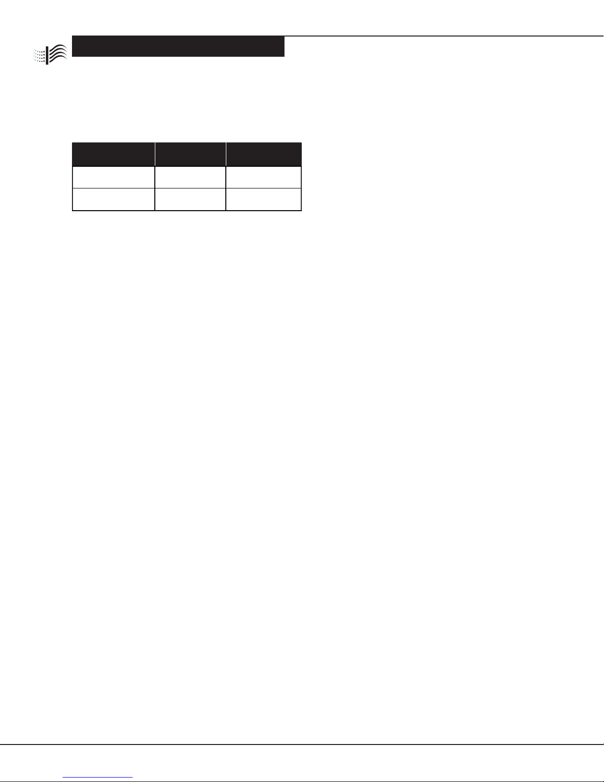
Table 1: Specicaons
Components
Cabinet: Constructed of heavy gauge galvanized steel
to resist corrosion and provide trouble-free installaon.
Holes are provided to facilitate mounng to the
ductwork or air handling equipment.
Power Box: Removable. Contains the power switch,
performance indicator light, safety interlock switch,
high-voltage power board, air-proving switch and
high-voltage contacts.
The power board is equipped with a variable resistor
(potenometer) to adjust high-voltage output. Output
has been pre-set for opmum eciency. As voltage
varies in extreme condions of dryness, humidity, or
proximity to hydro towers, raising or lowering
potenometer allows for proper voltage output.
Air-Proving Switch (APS): Integrated. Automacally
cycles air cleaner ON and OFF with the system fan.
The APS will detect airow (fan on) and energize the
air cleaner.
Collecng Cells: Consist of an ionizing secon and a
collector plate secon. The arrow on the cell must point
toward the system fan (in the direcon of the airow).
Prelters: Constructed of aluminum mesh to prevent lint
and large parcles from entering the collecng cells.
Carbon VOC Filters: Remove odors. Maximum of (3)
carbon VOC lters can be used at the same me.
120V MODELS AE14-1620-51 AE14-1625-51 AE14-2020-51 AE14-2025-51
240V MODELS AE14-1620-52 AE14-1625-52 AE14-2020-52 AE14-2025-52
House Size Area
(typical)
up to 2400 ²
up to 223 m²
up to 3000 ²
up to 279 m²
up to 3000 ²
up to 279 m²
up to 4000 ²
up to 372 m²
Airow
up to 1200 CFM
up to 2040 m³/hr
up to 1400 CFM
up to 2380 m³/hr
up to 1400 CFM
up to 2380 m³/hr
up to 2000 CFM
up to 3400 m³/hr
Duct Size
16 x 20 in
40.5 x 51.0 cm
16 x 25 in
40.5 x 63.5 cm
20 x 20 in
51.0 x 51.0 cm
20 x 25 in
51.0 x 63.5 cm
Unit Weight
35 lbs
15.9 kg
37 lbs
16.8 kg
37 lbs
16.8 kg
41 lbs
18.6 kg
Input Voltage
AE14-XXXX-51 models
AE14-XXXX-52 models
120 V 60 Hz
220 V 50 Hz
120 V 60 Hz
220 V 50 Hz
120 V 60 Hz
220 V 50 Hz
120 V 60 Hz
220 V 50 Hz
Power Consumpon
(when operang)
30 Was
30 Was
30 Was 30 Was
Opons Available • Power Cord • Power Cord • Power Cord • Power Cord
Cercaons: C22.2 NO. 187-09 (R2014) – CSA Standard for Electrostac Air Cleaners UL 867 UL Standard for Electronic Air Cleaners.
This device is cered for shock and electrical hazard only
Figure 2
Collecting cells (2)
Prefilters (2)
Cabinet
Power box
Performance
indicator light
Power switch
Door
Activated carbon VOC
filters (3)
Figure 2: Air Cleaner Components

FILTRATION
FILTRATION
WWW.CLEANCOMFORT.COM 5
IO-AE14-5
INSTALLATION
100% Airow
No Carbon
VOC Filters
100% Airow
With Carbon
VOC Filters
40% Airow
No Carbon
VOC Filters
40% Airow
With Carbon
VOC Filters
0.158 0.250 0.030 0.060
Static Pressure
The stac pressure drop across the air cleaner will vary
with CFM and whether the carbon VOC lters have been
installed in the unit.
Table 2: Pressure Drop (Inches w.c.)
Installation
Locaon:
The air cleaner must only be installed in the return air duct,
as close to the fan compartment as possible. This locaon
provides the most even airow across the collecng cells
and helps the air cleaner to keep the system motor, blower,
and cooling coil clean. The installaon can be vercal or
horizontal. When choosing a locaon, there must be ade-
quate room to wire the air cleaner and remove prelters,
collecng cells, and power box for maintenance.
Note: Once the air cleaner has been installed, do not allow
the placement of any device such as a new hot water heater,
water soener, gas pipe, or electrical cable
to be put 24 in. (61 cm) in front of or within
6 in. (15 cm) from top of air cleaner. This
distance is needed to allow access for the
removal of lters and air cleaner parts, which
are necessary for maintenance or servicing.
Dimensions — in (cm)
MODEL A B C D E F G H
AE14-1620-51
AE14-1620-52
19.8
(50.4)
15.9
(40.5)
23.2
(58.9)
13.1
(33.3)
20.7
(52.5)
1.3
(3.2)
23.7
(60.2)
21.2
(53.9)
AE14-1625-51
AE14-1625-52
19.8
(50.4)
15.9
(40.5)
26.1
(66.3)
13.6
(34.6)
24.1
(61.2)
1.0
(2.5)
26.6
(67.7)
25.8
(65.4)
AE14-2020-51
AE14-2020-52
24.7
(62.8)
20.8
(52.9)
21.2
(53.9)
18.0
(45.7)
18.7
(47.5)
1.3
(3.2)
21.7
(55.2)
21.2
(53.9)
AE14-2025-51
AE14-2025-52
24.7
(62.8)
20.8
(52.9)
25.8
(65.4)
18.0
(45.7)
23.3
(59.1)
1.3
(3.2)
26.3
(66.8)
25.8
(65.4)
Table 3: Air Cleaner Dimensions
Figure 3: Pressure Drop across Air Cleaner
2.80
Figure 4: Dimensions

FILTRATION
FILTRATION
WWW.CLEANCOMFORT.COM
6IO-AE14-5
INSTALLATION
Figure 5: Air Cleaner
Installaon Locaon
Allow 24 in. (60 cm) clearance for maintaining air cleaner
Allow 6 in. (15 cm) clearance for power box removal.
Installation Location with Humidier
A humidier should be installed in the furnace warm
air duct. However, it may be installed in the return duct
without causing problems to the air cleaner. Care must
be taken to ensure that the humidier does not leak, as
this may cause arcing and a mineral deposit to build up
on the collecng cells.
An atomizing type humidier should be installed
downstream from the air cleaner. If the atomizing type
humidier is installed upstream, high humidity, salts and
minerals may decrease the eciency of the collecng
cells and cause service problems.
If the atomizing type humidier must be installed
upstream, the following precauons should be taken:
1. Atomizing type humidier must be installed as far
from the air cleaner as possible.
2. Collecng cells must be washed frequently to
prevent a mineral deposit build-up.
Installation Location with Air Conditioner
Whenever possible, the air cleaner should be installed
upstream of the cooling coil. This locaon will clean the
air before it reaches the evaporator coil.
Installation Steps
1. Remove exisng equipment lter (if present) and
clean blower compartment: Thoroughly clean the
blower compartment, since your air cleaner can not
remove accumulated dirt from the blower chamber
and distribuon ducts.
2. Open air cleaner access door. Slide lters and
collecng cells out of cabinet.
3. Installing the cabinet: Holes are provided to aach
cabinet to ductwork or equipment. If the adjoining
ductwork is anged, install the screws so that the
screw heads are inside the cabinet. This will help
prevent damage to prelter and carbon VOC lters
during removal for cleaning. Never put screws or
rivets into the removable power box.
4. Transions: If the air duct does not t the air cleaner
opening, a gradual transion is recommended to
reduce air turbulence through the air cleaner and
ensure its ecient operaon. A maximum of 20° of
expansion, or approximately 4 inches per running foot
(10 cm per 30 cm ), is recommended for each side of
the transion ng.
Do not reduce ductwork size to t a smaller
air cleaner. This will increase the velocity of
airow and may decrease cleaning eciency.
5. Turning vanes: If the air cleaner is installed adjacent
to an elbow or angle ng, eld-installed turning
vanes are recommended to improve air distribuon
across the collecng cells.
6. Seal the joints in the return air system: All joints
between the air cleaner, the heang / cooling
equipment and the return air duct should be sealed
to prevent dust from entering the clean air stream.
7. Replace the prelters in the track on the air entering
side of the air cleaner. Place new carbon VOC lters
into the air cleaner. Space lters evenly across the
discharge opening of air cleaner. Never put more
than 3 carbon VOC lters in the air cleaner, as this
may cause a problem with airow.
The collecng cells are placed between the tracks, with
the arrow on cell poinng towards the fan. The cell
handle may need to be reposioned if the airow is in
a dierent direcon than the le to right set up. The
handle should face the door. Close access door.
iWARNING!
Electrical shock can cause injury or death. Be certain main
line disconnect switch is OFF before wiring.

FILTRATION
FILTRATION
WWW.CLEANCOMFORT.COM 7
IO-AE14-5
WIRING
Wiring
Wiring should only be performed by qualied personnel.
All wiring must comply with all applicable codes and
standards. The voltage of the power source must match
the voltage indicated on the air cleaner. The air cleaner
must operate ONLY when the system fan is running.
Make sure the air cleaner is properly grounded.
If the air cleaner is equipped with a cord and plug, the air
cleaner can be plugged into an outlet within 6 feet of the
unit. Do not use an extension cord if the outlet is too far
away. Have an electrician wire in a new outlet closer to
the air cleaner.
If the air cleaner is not equipped with a cord, then wire the
air cleaner directly to a power source, as indicated on the
rang label, preferably to the same source that is supplying
power to the furnace or air handler. The APS will power the
air cleaner when there is sucient airow to acvate the
sensor. See Figure 5.
Note: The ORANGE power switch will be lit even if there
is no airow.
This 120VAC air cleaner may only be wired to the EAC
contacts on the system module if these contacts carry
120 VAC power. Before wiring this air cleaner to the system
module, check the specicaons of the furnace or air
handler to ensure the system module has sucient unused
capacity to power this air cleaner with the fan operang in
all condions. The air cleaner uses approximately 30 Was
when operang. Some systems do not power the EAC
contacts on the system module on low speed.
System Check
Perform the following system check before operaon.
1. Replace prelters, collecng cells and carbon VOC
lters. Close the access door.
2. Turn air cleaner power switch ON. Ensure system
fan is operang. Both the power switch light and
performance indicator light should be lit. The power
switch light indicates the air cleaner has unit voltage.
The performance indicator light shows that the
air cleaner is operang.
Note: There may be some arcing or snapping sounds from
the collecng cells. This is normal when the unit is new.
In about two weeks, as the sharp edges of the cells become
smoother, the arcing will disappear.
Operation
The air cleaner will run as long as there is adequate airow
through the ducts. The air cleaner will not run if the system
fan is o.
To improve the performance of your air cleaner, these
simple steps are recommended:
3. Run your heang/cooling system fan connuously,
on low speed if available, since your air cleaner only
removes parculate maer when the system fan is
operang.
4. Ensure there are no obstrucons to airow (for
example, from furniture or carpets) in front of the
return air grilles so that air moves freely to the heang/
cooling equipment.
5. Check for proper operaon of the system fan.
Figure 6: Air Cleaner Schemac
(with Air-Proving Switch)

FILTRATION
FILTRATION
WWW.CLEANCOMFORT.COM
8
CHECKOUT
IO-AE14-5
When operang normally, with the fan running, the air
cleaner should have both the orange power switch
light and the green performance indicator light ON. If the
fan is running and the lights are not on, see the Trouble-
shoong Guide for probable causes and remedies.
iCAUTION!
For most troubleshoong, the cells should be removed
from the air cleaner. A short in one of the cells will cause
the power board to shut down and the performance light
will stay o. Unless otherwise directed, remove the cells
from the unit when tesng.
iWARNING!
Electronic air cleaners use high voltage (low amperage)
power. Only trained personnel should perform service.
Electric shock can cause injury or death.
iWARNING!
When performing LIVE tests in the power box, NEVER touch
any components inside the air cleaner other than what is
menoned in the tests. Components carry dangerous
voltages and extreme care must be taken.
CHECKOUT – Visual
Visually check the air cleaner installaon to verify that:
• The arrows on the front of the collector cells are
poinng in the direcon of the airow.
• The aluminum mesh prelter is installed on the
upstream side of the air cleaner and the acvated
carbon VOC lters are on the downstream side.
• The handles on the collector cells are facing the front
of the air cleaner cabinet.
• The collector cells and aluminum prelters are clean
and dry.
• All joints in sheet metal between the air cleaner and
the heang and cooling system are sealed.
• Previously-installed furnace lter has been
removed (if present) and blower compartment
has been cleaned.
When you have performed the preceding physical
checkout, proceed to do the operaonal checkout
that follows:
CHECKOUT – Operational
1. Replace any access doors removed during the
Installaon.
2. Toggle the air cleaner power switch to the ON
posion and energize the furnace or air handler
(system) fan.
3. Verify that the orange power switch is ON (lighted).
The orange light shows that there is power supplied
to the air cleaner.
4. Verify that the green performance indicator light
is ON. The green light shows that the high voltage
power supply is working correctly.
5. Turn OFF the system fan. The green light should go
OFF aer a few seconds, but the orange light should
remain ON.
6. For furnaces or air handlers with a mul-speed fan,
air cleaner operaon should be veried by repeang
steps 3 through 5 for each fan speed.
7. For any issues related to air cleaner performance,
refer to Troubleshoong and Service secons in this
manual.
FILTRATION
FILTRATION
WWW.CLEANCOMFORT.COM 9
MAINTENANCE
IO-AE14-5
Maintenance
It is important to perform regularly-scheduled mainte-
nance of the air cleaner. For best performance of the air
cleaner and to keep airow restricon low, it is recom-
mended that the collector cells be cleaned at least twice a
year or when the stac pressure across the air cleaner
reaches 0.5 inches w.c. If you nd signicant loading of
parculates on the collector cells when you perform the
rst cleaning, clean the cells more frequently. The prel-
ters should be cleaned regularly and the post lters should
be replaced at least twice per year.
Cell and Prelter Cleaning
The collecng cells and prelters must be cleaned on a
regular basis for best performance of the air cleaner.
As the collector cells become coated with trapped
parculates, the cleaning eciency of the air cleaner is
reduced and the resistance to airow (stac pressure) is
increased. The recommended frequency of cleaning will
depend on several factors, including number of family
members, pets, acvies (such as cooking or woodwork-
ing), leaving the windows open and smoking. Use the
Cleaning Record to help keep track of scheduled cleanings.
Cleaning the Collector Cells
1. Remove access door, collecng cells and prelters.
2. Place cells in a laundry tub. Rinse with hot water
(maximum 120°F/49°C) and spray completely with
DAX Detergent (or a non-chlorine, non-corrosive,
non-abrasive liquid household detergent). Allow de-
tergent to run down both sides of plates and ionizing
wires. Let stand for 5 minutes or ll up laundry tub
with water and DAX Detergent, and dunk cells up and
down unl water is dirty.
3. If dirt remains on the cell plates, let the cells soak in a
soluon of DAX Detergent and water for 30 minutes.
4. When the collector cells are clean, drain the tub
and rinse cells thoroughly with hot water (maximum
120°F/49°C).
5. Remove accumulated parculate from the ionizing
wires with an old toothbrush. Slide the brush bristles
over the wire and gently drag the brush up and down
the wire once. Be very careful when cleaning the
wires as they become very brile with age and can be
very sharp. Tilt collector cells on a 45° angle on their
short side.
6. Tilt collector cells on a 45° angle on their short side,
with arrows poinng sideways. Allow to dry com-
pletely, approximately 12-24 hours. Drying me can
be reduced by using a hair dryer on the collector cells
before replacing them in the air cleaner cabinet.
7. Do not place the cells in the air cleaner if they
are wet.
Cleaning the Prelters
1. To clean the prelters, rst vacuum the upstream side
to remove larger trapped parcles.
2. Then, wash the prelters with DAX Detergent, rinse
and let dry. Do not wash in the same water as
collecng cells.
iWARNING!
Make sure to turn air cleaner and system fan OFF before
performing any maintenance or removing any components.
iCAUTION!
Metal edges of the air cleaner collector cells, ionizing wires
and system ductwork are very sharp and can cause personal
injury. Carefully handle the cell or wear protecve gloves to
avoid cuts from metal edges.
iCAUTION!
Damage to cells may occur if improperly handled or washed.
Do not wash cells in a dishwasher. Never use any object to
clean between the cell plates, as this may cause damage to
plates or ionizing wires. Never place cell in oven to dry.
The edges of the cell may be sharp – handle with care.

FILTRATION
FILTRATION
WWW.CLEANCOMFORT.COM
10
MAINTENANCE
IO-AE14-5
Reinstalling the Cells and Prelters
1. Once dry, inspect the cells for broken ionizer wires
and bent collector plates. Repair as necessary or
contact an authorized Clean Comfort service
technician to repair.
2. Re-insert the prelters into the upstream
prelter guides.
3. Re-insert the collector cells into the guides in the
boom center of the air cleaner cabinet; the airow
arrow points downstream (towards the furnace or
air handler) and the handle faces outward.
4. Firmly close the access door and turn power switch
ON. If the performance light does not come on or
arcing occurs, turn air cleaner OFF and allow air from
system fan to dry cells completely.
Replacing the Carbon VOC Filters
1. The acvated carbon VOC lters help remove odors
and light gases from the air exing the air cleaner.
They should be replaced every six months, or more
frequently with heavy use and should be done as part
of the scheduled cleaning when the cells and prelters
are cleaned. Carbon VOC Filters are NOT washable.
2. Replacement carbon VOC lters are available in the
same size and conguraon as the original unit. They
can be purchased from your Clean Comfort authorized
service technician.
1. Turn air cleaner power switch OFF
2. Turn OFF system fan
3. Open access door
4. Remove collecng cells from air cleaner
5. Remove the used carbon VOC lters from air cleaner
6. Put new carbon VOC lters into air cleaner. Space lters
evenly across the discharge opening of air cleaner.
Never put more than 3 carbon VOC lters in the air
cleaner, as this may cause a problem with airow.
Figure 7: DAX Detergent and Carbon VOC Filters are available
from your installer or dealer.
Maintenance Parts
Item Part #
DAX 32 oz Spray Bole AEP-FS9900
Replacement Carbon VOC Filters:
AE14-1620-51,-52 (Set of 3) AEP-1156-3
AE14-1625-51,-52 (Set of 3) AEP-1156-3
AE14-2020-51,-52 (Set of 3) AEP-1856-3
AE14-2025-51,-52 (Set of 3) AEP-1856-3
Cleaning Record
The collecng cells and prelters must be cleaned on a
regular basis for the air cleaner to funcon at its peak
eciency. The frequency of cleaning will vary from
one house to another. On average, the cells should be
cleaned every 3 months. Use the chart below to keep
track of your cleaning schedule.
Cleaning Record
Date Cleaned Performed by

FILTRATION
FILTRATION
WWW.CLEANCOMFORT.COM 11
TROUBLESHOOTING
IO-AE14-5
1. Remove both cells from the air cleaner cabinet.
Replace the cabinet door.
2. Toggle the air cleaner’s orange power switch ON,
and turn the HVAC fan ON.
3. If the green performance indicator light is sll OFF,
check the power board for an arc to ground at HV1
or HV2. Refer to Troubleshoong secon ①.
4. If there is a good arc and the performance indicator
light is sll OFF, then replace the light. Refer to Service
secon A “Replacing a Performance Light”.
If the performance indicator light comes ON, check
the cells for a fault. Refer to Troubleshoong secons
④, ⑤, and ⑥.
5. If there is no arc, test the output voltage of the
transformer. Refer to Troubleshoong secon ④.
If there is transformer output, replace the power
board. Refer to Service secon B) “Replacing a
Power Board”If there is no transformer output,
check for output of the APS. Refer to Troubleshoong
secon ③.
• If there is output from the APS, replace the trans-
former (refer to Service secon C) “Replacing the
24 V Transformer”) and retest the power board for
an arc. Refer to Troubleshoong secon ①.
• If there is no output from the APS, jumper terminals
3 & 4 on the APS and retest the output. If there is
APS output with the jumper installed, replace the
APS. Refer to Service Secon D) “Replacing an Air
Proving Switch (APS).
6. If there is sll no output from the APS, check the output
voltage from the power switch.
7. If there is no voltage from the power switch, test the input
to the switch. If there is input, replace the power switch.
8. If there is no input to the switch, check the interlock
switch and the supply voltage.
Troubleshooting
The air cleaner, when operang normally with the fan
running, should have both the orange power switch light
and the green performance indicator light ON. If the fan is
running and the lights are not on, follow instrucons below
for probable causes and remedies.
Quick Check (Orange Power Switch Light ON, Green
Performance Indicator Light OFF)Detailed Troubleshooting
① Tesng For High Voltage at Power Board
With the collecng cells out of the unit, the door on the unit
and the system fan on high speed, turn the air cleaner ON.
With a long shaed screwdriver with a plasc handle, short
between the grounded side of the power box and the HV1
terminal of the power board. If you draw a good spark,
there is high voltage from the power board.
② Measuring High Voltage at Power Board
A high voltage meter capable of measuring up to 10,000
VDC is required to test the voltage.
iCAUTION!
For most troubleshoong, the cells should be removed
from the air cleaner. A short in one of the cells will cause
the power board to shut down and the performance light
will stay OFF. Unless otherwise directed, remove the cells
from the unit when tesng.
iWARNING!
When performing LIVE tests in the power box, NEVER
touch any parts other than what is menoned in the tests.
Components carry dangerous voltages and extreme care
must be taken.
1. The air cleaner should be ON with the cells installed,
the door closed and the system fan running.
The air cleaner should be on at least 5 minutes
to allow voltage to stabilize. The cells and ionizing
wires must be clean.
2. Remove the cover from power box.
3. Connect the ground of the high voltage meter to an
unpainted surface in the power box.
4. Check terminals HV1 and HV2 on the power board to
determine if voltage is present. See Table 3 for values
If no voltage is present, remove both cells from the
air cleaner and replace door. Recheck the voltage at
HV1 and HV2
If voltage is present, the problem is with one of the
cells or the wiring to the copper contacts.
With a ashlight, look into the cabinet to check
condion of the copper contacts.
If the contacts are not bent, replace one cell and
retest voltage. If cell is OK, test the other cell. If the
problem is with a cell, see Troubleshoong secons
⑥, ⑦, and ⑧.
If there is no voltage with both cells removed,
check the power board, APS and transformer to
make sure that they are funconing correctly.
FILTRATION
FILTRATION
WWW.CLEANCOMFORT.COM
12
TROUBLESHOOTING
IO-AE14-5
MODEL Max. Voltage on
Plates (KVDC)
Max. Voltage on
Ionizer (KVDC)
AE14-1620-51
AE14-1625-51 4.8 - 5.3 (HV1) 7.2 - 8.0 (HV2)
AE14-2020-51
AE14-2025-51 4.8 - 5.2 (HV1) 7.2 - 7.8 (HV2)
Table 4: Power Board Voltage Sengs (with load)
The voltage will be higher without the cells in the unit.
③ Tesng Air Proving Switch (APS)
The APS sensor must sit in the plasc bushing to operate
correctly. The sensor is very sensive and operaon may
be aected by cold ambient temperatures, an HRV/ERV,
or a fresh air duct connected to the return air duct just
upstream of the air cleaner.
The APS uses a triac in its output circuit, which aects the
voltage sine wave. Measuring voltage with a regular digital
voltmeter may give a false reading. To check the output
from the APS, use a true RMS (root mean square) meter to
measure the output at terminals 1 and 4 of the APS. The
output should be between 102 and 115 VAC or 205-230
VAC, depending on the airow across the sensor
When the air cleaner is turned on without airow, the APS
sensor heats up, and aer 20-30 seconds opens the circuit
to turn OFF the power board. When the fan starts up (the
sensor is cooled), the circuit will close, the power board is
turned on, and the performance light will come on within
a few seconds.
The light on the power switch will be lit even when the
APS is open.
If the power board fails to come on with the fan on, check
that the sensor is properly seated in the boom of the
plasc bushing, in the front of the power box. To check the
APS for proper operaon remove the collecng cells, turn
the unit ON without the fan on. The power board should
come on immediately, and then turn OFF in 20-30 seconds
as the sensor heats up. To check sensor, blow directly on
it lightly. This should acvate the power board within 10
seconds. Service the sensor carefully. The sensor leads
are live. If the APS does not turn the power board and
performance indicator on, by-pass the APS by placing a
jumper between wires 3 & 4 on the APS. This removes the
APS from the circuit.
Note: If the airow through the air cleaner is less than
360 CFM, the APS sensor may not have enough airow
to acvate the air cleaner. In very low airow applicaons,
the air cleaner may need to be controlled by wiring it to
the EAC contacts on the system control module. In this
case, the APS must be disabled by connecng terminals
3 and 4 together.
See Wiring secon for informaon on how to wire the
air cleaner to the EAC contacts on the furnace or air
handler control module.
If there are no EAC contacts on the system control
module or they are not powered on low speed then a
relay will have to be installed to acvate the air cleaner
when the fan starts. The APS will have to be disabled.
④ Tesng the 24 V Transformer
1. Remove power box cover.
2. Disconnect the leads of the 24 V transformer from the
power board. See Fig. 5. Do not short leads.
3. The air cleaner should be ON. The system fan should
be running on high speed. The access door should be
closed.
4. Measure voltage across the leads with a voltmeter.
Voltage should read 25 - 28 VAC.
5. If no voltage is present, check operaon of the APS.
6. Reconnect leads to the power board.
7. Replace power box cover.
⑤ Seng Voltage of Power Board
High voltage can be adjusted with high voltage
potenometer if required. See Table 4 below.

FILTRATION
FILTRATION
WWW.CLEANCOMFORT.COM 13
TROUBLESHOOTING
IO-AE14-5
Voltage on the power board may drop below required level
when installaon area is too damp, too cold, or if there is a
leakage of water from a humidier. Voltage on power board
may be too high when installaon area is too dry or too hot,
or home is in close proximity to hydro towers or situated in
remote farm land areas. By adjusng the HV Adj. potenom-
eter, the voltage can be set to opmum level. A high voltage
meter capable of measuring 10,000 VDC is required. To test
and adjust voltage level, perform the following procedure:
1. Turn the air cleaner OFF.
2. Remove the power box cover.
3. Connect the ground of the high voltage meter to an
unpainted surface in the power box.
4. Turn ON the air cleaner and wait 5 minutes before
checking voltages to allow voltages on cells to stabilize.
The cells and ionizing wires must be clean.
5. Measure the voltages at HV1 and HV2 on the
power board.
6. Adjust the HV Adj. potenometer unl the voltage
reading matches the voltage in Table 3. Adjusng the
potenometer clockwise decreases the voltage and
turning counter-clockwise increases the voltage.
7. Turn OFF the air cleaner.
8. Remove the high voltage meter.
9. Replace the power box cover.
10. Turn ON the air cleaner.
Seng Approximate Voltage without High Voltage Meter
A high voltage meter should be used to set the high
voltage. If one is not available, this method can be used.
This will only set an approximate voltage. Aer using this
method, the voltage should be reset with a high voltage
meter as soon as possible.
1. Remove power box cover.
2. Turn the HV Adj. potenometer fully counter-clockwise.
The air cleaner may arc or snap at this point.
3. Turn the HV Adj. potenometer clockwise unl the
arrow is at the half way point.
4. Replace power box cover.
⑥ Tesng for Voltage at The Cell
1. Open access door to air cleaner.
2. The cells must be in the air cleaner for this test
and the system fan should be on high speed.
3. Turn the air cleaner ON and press the safety
interlock switch lever.
4. Place a plasc handled screwdriver into the
direcon arrow slot. Do not apply excessive force.
5. If there is a good snap, then there is high voltage at the cell.
⑦ Tesng Cell for Bad Contacts
1. Open access door to air cleaner.
2. The cells must be in the air cleaner for this test and the
system fan should be on high speed.
3. Turn the air cleaner ON and press the safety interlock
switch lever.
4. Place a plasc handled screwdriver into the direcon
arrow slot. Do not apply excessive force.
5. There should be an inial snap when the plates are
shorted, then no sound. If a hissing occurs, then there
is a bad contact. Look along the top of the cell, with the
short sll in place. If there is a small arc between the
cell top and copper contact, then that is the bad contact.
Pull cell out and gently pull the copper contact down.
6. If an arc is not seen and there is a bad contact, then the
problem may be an internal contact in one of the cells.
7. Let up on safety interlock.
8. Close access door.
⑧ Tesng Cell with an Ohmmeter
To test the cell for a dead short or a bad contact, an
ohmmeter can be used.
Always discharge the cell with a screw driver before
tesng with an ohmmeter.
1. With the ohmmeter set on its lowest scale, take a
reading between the top center contact of the cell
and the ionizing ngers on the boom of the cell.
You should have connuity. If you do not, then there
is a bad contact between the center contact and the
top set of ionizing ngers.
2. Test the resistance between the top center contact
and the cell frame. You should read innite resistance.
If not, you have a short in the ionizing secon.
3. Take a reading between the two outside contacts on
the top of the cell. You should have connuity. If you
do not, then there is a bad contact between one of the
contacts to the live cell plate. Test each top outside
contact to the last plate in the cell to determine which
contact is not mang properly.
4. Test the resistance between the outside contacts
and the cell frame. You should read innite resistance.
If not, you have a short in the collecng secon.
FILTRATION
FILTRATION
WWW.CLEANCOMFORT.COM
14
TROUBLESHOOTING
IO-AE14-5
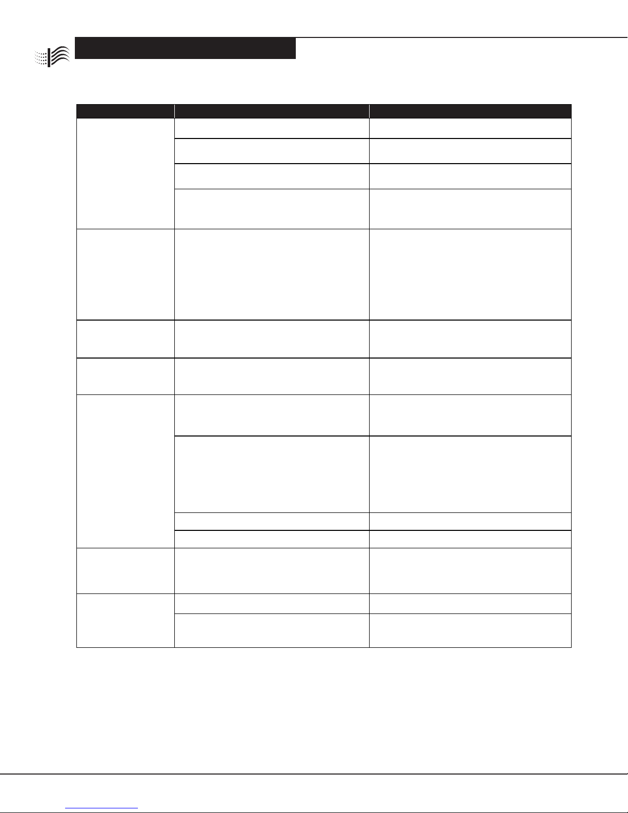
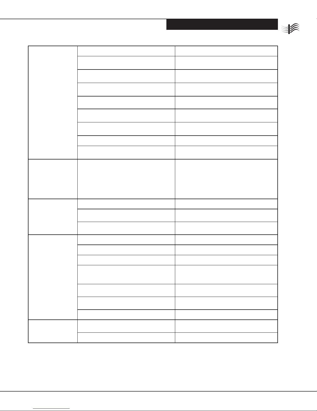
Table 5 Troubleshoong Guide
Problem Probable Causes Remedy
Unit does not
funcon correctly.
Power light and
performance
indicator light
are OFF.
System fan is not on. Turn system fan on.
Wiring improperly connected. Check wiring or verify that plug is inserted in
receptacle and receptacle is powered.
Defecve power switch. Check power switch for connuity with ohmmeter.
Replace if defecve.
Defecve safety interlock. Remove door and press safety interlock with a
screwdriver. If lights come on, bend interlock lever
towards front and close door.
Unit does not
funcon correctly.
Power switch light is
ON and performance
indicator light is OFF.
Short in cells due to:
1. Broken ionizing wire.
2. Large parcles wedged between cell plates.
3. Cells washed recently and are sll wet.
4. Cell end plate insulator is dirty or damaged.
5. Cell plate(s) are bent.
1. Remove wire or wire fragments. Replace.
2. Shake large parcles out or wash cell.
3. Allow cells to dry completely.
4. Clean or replace end plate insulator.
5. Straighten plates with pliers.
Defecve performance indicator light.
Determine whether high voltage is present by tesng
power board ② If voltage is present, replace
performance indicator light.
Defecve power board. Adjust high voltage potenometer on power board
counter-clockwise. If high voltage is not present,
replace power board.
Air Proving Switch (APS) sensor is
burnt out.
Remove power box lid and blow lightly for 10
seconds on APS sensor at boom of power box.
If light does not come on, replace APS.
Air Proving Switch is not geng enough airow
across the sensor.
Check that sensor is located in the plasc bushing
at the front of the power box.
Check that the return duct is installed ush to the
top and front edge of the air cleaner duct opening.
Ensure there is a minimum of 360 CFM of air to
the air cleaner.
O board 24V transformer is not working. Verify output of transformer. Replace if necessary.
Defecve power switch. Verify output of switch. Replace if necessary.
Power switch light is
OFF and performance
indicator light is ON.
Defecve power switch light. Replace power switch.
Cell makes loud
hissing noise
or causes radio
interference.
Internal cell contacts are not touching plates. Test contacts and repair.
Copper contacts on high voltage tray not making
good connecon on cell. With needle-nose pliers, gently pull contacts down
or replace contacts.
FILTRATION
FILTRATION
WWW.CLEANCOMFORT.COM 15
TROUBLESHOOTING
IO-AE14-5
Cells arcing
excessively
(power light and
performance
indicator light ON
or ashing).
Cells wet from washing. Allow cells to dry completely.
Parcles lodged in cell or broken ionizing wire. Wash cell. Shake parcle out of cell. Replace wire,
if necessary.
Ducts were not cleaned prior to installaon of
air cleaner. Clean ducts.
Cell plates are bent. Remove cells and adjust to original spacing using
needle-nose pliers.
Dirty cells. Wash cells and clean ionizing wires.
Voltage is too high. Adjust high voltage potenometer on power
board clockwise.
High voltage wires are on wrong
copper contact. Reposion high voltage wires on proper contact
(see Fig. 6).
Internal contact on cell out of alignment. Realign cell contact.
Humidier (if installed) is leaking water on
air cleaner. Repair humidier. If possible, move humidier to
dierent locaon.
Cells arcing
excessively at top
of cell near copper
contacts (power light
and performance
indicator light ON).
Copper contact on high voltage contact board is
broken or bent upward. If possible, pull down contacts with needle-nose
pliers or remove power box and replace contacts.
Cells not collecng
dirt (power light
and performance
indicator light ON).
Arrow on cells not poinng towards fan blower. Reposion cell handle and place cell in properly.
System fan is on “Automac” seng
(air cleaner not on connuously) Use “Fan On” system fan seng for connuous
fan operaon.
Not enough voltage on collecng cells. Adjust high voltage potenometer counter-
clockwise on power board.
Ozone odor Cell plates are bent. Straighten with needle-nose pliers.
Loose or broken ionizing wire. Replace wires.
Dirty cells. Wash cells and clean ionizing wires.
Air cleaner is on when system fan is not running.
Air cleaner wired incorrectly or air proving switch
is defecve.
Check operaon and wiring of air switch and air
cleaner.
Incoming voltage is higher than rated input. Adjust high voltage potenometer clockwise on
power board.
Air cleaner is oversized for house. Not enough
airow to cover surface area of cells. Use correct size of air cleaner.
Home is extremely dry. Repair or install central humidier.
White dust Clean lint dust is too heavy to remain airborne. Keep fan running connuously. Ensure that return
air grilles are not obstructed.
Gaps around air cleaner. Seal or use duct tape around air cleaner cabinet.

FILTRATION
FILTRATION
WWW.CLEANCOMFORT.COM
16 IO-AE14-5
SERVICE
Service
A) Replacing a Performance Light
Before replacing the performance light, turn OFF power
to the air cleaner at the source.
1. Remove the power box cover.
2. Disconnect the performance light wiring connected
to the LED terminals on the power board. Carefully
cut the wire es from the wire bundle.
3. Push the light out through front of power box.
4. Push the new light into the power box.
5. Connect the wiring to the LED terminals on the power
board. P3 - red; P4 - black. Route the wires away from
the high voltage wires or contacts.
6. Replace cover.
7. Return power to air cleaner. Test light.
B) Replacing a Power Board
Before replacing the power board, turn OFF power to the
air cleaner at the source or remove the plug.
1. Remove the power box cover.
2. Make note of posion of wires connected to the
LED, HV1, HV2 and 24 V terminals, then disconnect
these wires.
3. Remove the three hex nuts from the power board.
4. Remove the power board from the studs.
5. Place the new board onto studs with the 24 volt input
close to the transformer.
6. Replace the hex nuts removed in Step 3. Ensure the
star washer is in place over the steel spacer at the
ground locaon on the power board. For proper
grounding, the washer must be located on the top of
the steel spacer, under the power board.
7. Reconnect wiring to LED, HV1, HV2, and 24 V
terminals on the new power board.
8. Return power to air cleaner. Test power board.
9. Replace power box cover.
C) Replacing the 24 V Transformer
Before replacing the transformer, check the resistance
across the power board’s 24 V input terminals, without
the transformer connected. Resistance should read
above 20K ohms with an analog meter and above 4M
ohms with a digital meter. If the resistance readings are
below these values, the power board may be the cause of
the transformer failure.
Before replacing the 24 V transformer, turn OFF power to
the air cleaner at the source.
1. Remove power box cover.
2. Disconnect the secondary leads from the transformer
to the 24 V terminals on the power board. See Fig. 5.
3. Cut the primary leads (to the APS) close to the
transformer.
4. Remove the 2 hex head nuts from the transformer
studs.
5. Remove the transformer.
6. Place new transformer over studs and re-install 2 hex
head nuts to secure into place.
7. Connect secondary leads (white) to the 24 V terminals
on the power board (P1 & P2).
8. Wire nut primary leads from APS (cut in Step 3) to the
primary leads of the new transformer.
9. Replace power box cover.
10. Turn ON the power to the air cleaner and test
Note: The power board voltage has been set before
shipping. It is not usually necessary to reset the voltage
to the new load. If you do need to adjust the voltage,
refer to ⑤Seng Voltage of Power Board in the
Troubleshoong secon for more informaon.

FILTRATION
FILTRATION
WWW.CLEANCOMFORT.COM 17
IO-AE14-5
SERVICE
D) Replacing an Air Proving Switch (APS)
Before replacing the performance light, turn OFF
power to the air cleaner at the source.
1. Disconnect wiring from terminals 1, 2, 3, and 4 on the
APS. See Fig. 6.
2. Remove the circuit board from the studs by removing
the two nuts. Do not remove the spacers.
3. Install the new APS on the studs and secure with the
nuts. Ensure sensor protrudes only to the boom of the
plasc bushing.
4. Connect wiring to terminals on APS. Wiring from the
power switch is connected to terminals 2 and 3. Wiring
to the transformer is connected to terminals 1 and 4.
5. Test the new APS.
E) Removing Power Box
1. Turn the main system switch OFF or disconnect the
power cord.
2. Remove the power box cover.
3. If the unit does not have a cord, disconnect the source
wires to the air cleaner. Cap o the wires so the system
can sll be operated.
4. Remove the two nuts holding the power box to the
cabinet.
5. Slide the power box forward then up to remove it from
the cabinet.
6. If you are removing the power box for any length of
me, tape a cover over the top opening to prevent air
from entering into the system.
F) Replacing a Tungsten Ionizing Wire
Replacement wires are cut to the correct length and have
eyelets at each end for easy replacement.
1. Turn OFF power to air cleaner.
2. Remove cell from air cleaner.
3. Remove all parts of broken wire from the cell.
If necessary, the cell may be used temporarily with
one wire missing unl a replacement is received.
4. Place one end of the loop over the nger at the boom
of the cell.
5. Using needle-nose pliers, grip the other end of wire near
the boom of the top loop. Pull the wire up toward the
top nger. As you apply tension, the boom nger will
give, allowing the placement of the loop around the
top nger.
6. Install cell in air cleaner.
7. Return power to air cleaner.
8. Test cell for proper operaon.
FILTRATION
FILTRATION
WWW.CLEANCOMFORT.COM
18
PARTS LIST
IO-AE14-5
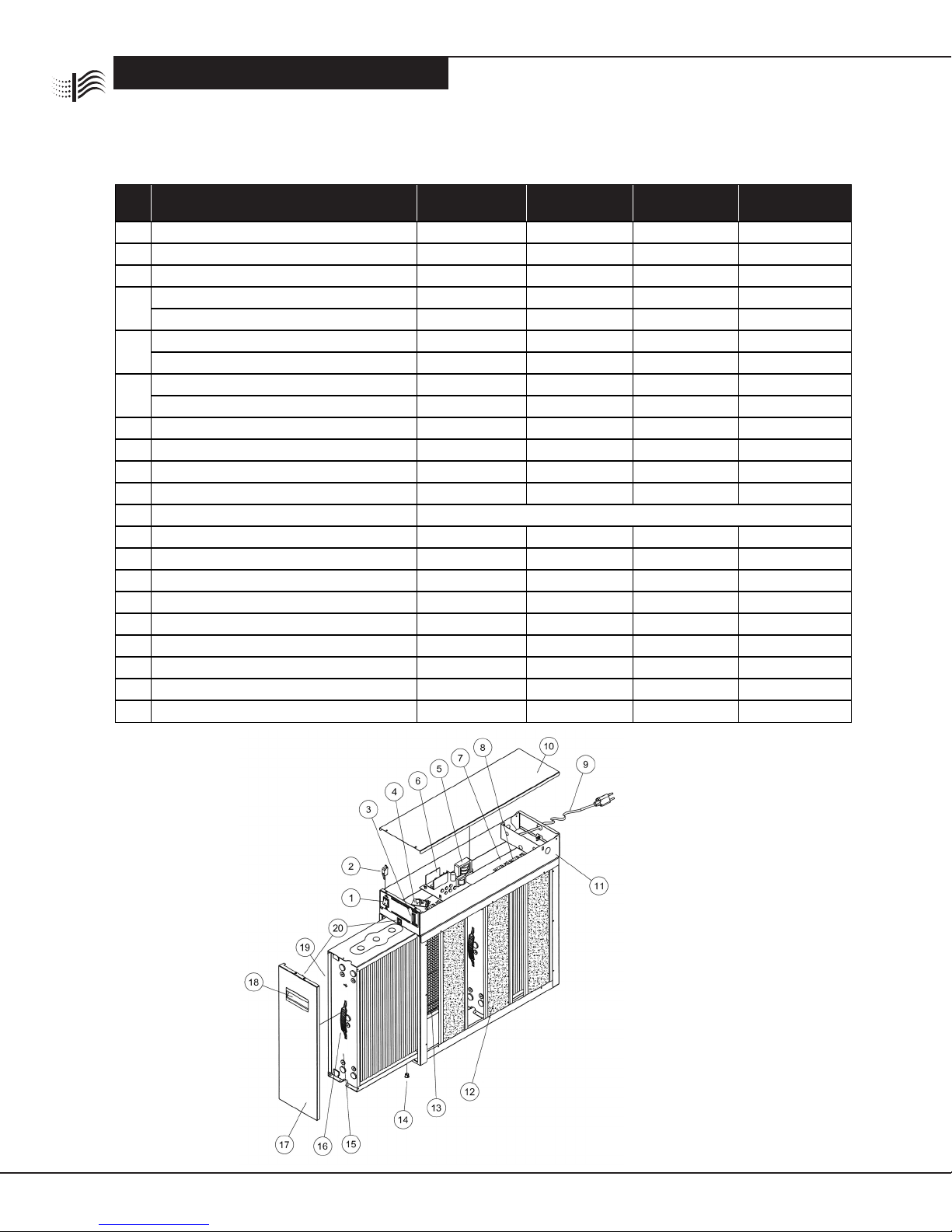
Table 6: Air Cleaner Components List
For more informaon on ordering parts, call 1-800-267-8305 or your installing contractor.
Figure 8: Air Cleaner Component View
#Part Descripon
AE14-1620-51
AE14-1620-52
AE14-1625-51
AE14-1625-52
AE14-2020-51
AE14-2020-52
AE14-2025-51
AE14-2025-52
1 Power Switch
R1-0205 R1-0205 R1-0205 R1-0205
2 Safety Interlock Switch
R1-0202 R1-0202 R1-0202 R1-0202
3 Performance Indicator Light (Green LED)
R1-0123 R1-0123 R1-0123 R1-0123
4 Air Proving Switch - 120VAC models
D1-0217 D1-0217 D1-0217 D1-0217
Air Proving Switch - 220VAC models
D1-0217E D1-0217E D1-0217E D1-0217E
5 24 Volt Transformer - 120VAC models
D1-053D D1-053D D1-053D D1-053D
24 Volt Transformer - 220VAC models
D1-053E D1-053E D1-053E D1-053E
6 Power Board - 120VAC models
D1-055D D1-055D D2-055D D2-055D
Power Board - 220VAC models
D1-055E D1-055E D2-055E D2-055E
7 Fibreboard (with 4 Copper Contacts)
D0-0521 D1-0521 D2-0521 D8-0521
8 Copper Contact
R1-9925 R1-9925 R1-9925 R1-9925
9 Cord Assembly (Oponal)
R1-062D R1-062D R1-062D R1-062D
10 Cover for Power Box
D0-0509 D1-0509 D0-0509 D1-0509
11 Power Box Complete (No Cover) Depends on opons with power box
12 Carbon VOC Filters (Set of 3)
AEP-1156-3 AEP-1156-3 AEP-1856-3 AEP-1856-3
13 Prelter
R0-0855 R1-0855 R2-0855 R8-0855
14 Cell Guide (Plasc)
R1-0603 R1-0603 R1-0603 R1-0603
15 Collecng Cell
D0-0400 D1-0400 D2-0400 D8-0400
16 Cell Handle
R1-0484 R1-0484 R1-0484 R1-0484
17 Door (with Plasc Clip & Handle)
D0-0632 D1-0632 D2-0632 D2-0632
18 Door Handle (Plasc)
R1-0634 R1-0634 R1-0634 R1-0634
19 Ionizing Wire
D1-0443 D1-0443 D2-0443 D2-0443
20 Male & Female Door Clip Set
R1-0636 R1-0636 R1-0636 R1-0636
SERVICE

FILTRATION
FILTRATION
WWW.CLEANCOMFORT.COM 19
IO-AE14-5
NOTES:

20 WWW.CLEANCOMFORT.COM IO-AE14-5
FILTRATION
FILTRATION
AIR CLEANERS
CLEAN COMFORT™ ELECTRONIC AIR CLEANER
LIMITED FIVE YEAR WARRANTY
This Clean Comfort™ product is warranted by Daikin North
America LLC (“Daikin”) to the original owner to be free from
defects in material and workmanship, under normal use and
maintenance, within its listed capacity, for a period of ve years
from the date of purchase, except however, for the prelters
and carbon VOC lters, which will have to be replaced from
me to me depending upon the use. This Clean Comfort™
product must not have been moved from the site of original
installaon. Daikin’s exclusive obligaon, and the owner’s
sole remedy, under this warranty shall be for Daikin to supply,
without charge through a Daikin authorized service dealer,
a replacement for any covered part of the Air Cleaner which
is found to be defecve and is returned by the owner or a
qualied servicing Daikin dealer prepaid, together with the
serial number, date of installaon, and proof of purchase. If the
date of installaon is unknown, Daikin will guarantee the unit
for a period of sixty (60) months from the date of manufacture
listed on the product’s rang plate. Any part replaced pursuant
to this warranty is warranted only for the unexpired poron of
the warranty term applying to the original part.
THIS WARRANTY DOES NOT COVER ANY LABOR OR OTHER
COSTS incurred for diagnosis, repairing, removing, installing,
shipping, servicing, or handling of either defecve parts or
replacement parts.
LIMITATIONS - THE EXPRESS WARRANTY CONTAINED HEREIN
IS IN LIEU OF ALL OTHER EXPRESS WARRANTIES. IMPLIED WAR-
RANTIES INCLUDING WARRANTIES OF MERCHANTABILITY ARE
LIMITED TO THE DURATION OF THE WARRANTY DESCRIBED
HEREIN. THE EXPRESS WARRANTY MADE HEREIN MAY NOT
BE ALTERED, ENLARGED, OR CHANGED BY ANY DISTRIBUTOR,
DEALER OR OTHER PERSON WHATSOEVER.
CONSEQUENTIAL OR INCIDENTAL DAMAGES FOR THE BREACH
OF ANY WARRANTY, WHETHER EXPRESS OR IMPLIED, FOR ANY
OTHER CONTRACT BREACH, OR FOR NEGLIGENCE OR OTHER
TORT, INCLUDING BUT NOT LIMITED TO LOSSES OF PROPERTY
ARISING OUT OF THE FAILURE OF THIS EQUIPMENT TO OPERATE
FOR ANY REASON WHATSOEVER, ARE EXCLUDED.
Some states and provinces do not allow limitaons on how
long an implied warranty lasts or the exclusions of conse-
quenal or incidental damages, so the above limitaons and
exclusions may not apply to you. This warranty gives you
specic legal rights and you may also have other rights which
vary from state to state or province to province.
DAIKIN WILL NOT BE RESPONSIBLE FOR:
1. Normal maintenance including cleaning of electronic collect-
ing cells and replacement of prelters and carbon VOC lters
as outlined in the Installaon and Maintenance Instrucons.
2. Damage or repairs needed as a consequence of any mis-
applicaon, faulty installaon, abuse, improper servicing,
unauthorized alteraon, or improper operaon.
3. Damage as a result of oods, winds, res, lightning,
accidents, corrosive atmosphere, or other condions
beyond the control of Daikin.
4. Parts not supplied or designated by Daikin.
5. Products installed outside the connental U.S.A., Alaska,
Hawaii and Canada.
Model No.
Serial No.
Date Of Installation
Installed By
Owner’s Name & Address
ATTENTION INSTALLING CONTRACTOR: IF FAILURE SHOULD
OCCUR, DO NOT RETURN PRODUCT TO THE DISTRIBUTOR.
CALL THE TOLL-FREE HOTLINE 1-800-267-8305.
Daikin North America LLC
351 North Rivermede Road
Concord, ON L4K 3N2
FOR TECHNICAL ASSISTANCE, CALL THE AIR CLEANER
HOTLINE TOLL FREE 1-800-267-8305
Our connuing commitment to quality products may mean a change in specicaons without noce.
© 2015 DAIKIN NORTH AMERICA LLC
Houston, Texas • USA
Email: info@cleancomfort.com • 1-800-267-8305 • Fax: 1-416-213-5593
This manual suits for next models
7
Table of contents
Other CLEAN COMFORT Air Cleaner manuals

Popular Air Cleaner manuals by other brands


CLEANAIRE
CLEANAIRE CAHP-50 02 Series instruction manual

Sencor
Sencor SDH 1210WH Translation of the original user manual

Wizard
Wizard Lion instruction manual

KRUEGER
KRUEGER PAC Series Installation, operation and maintenance manual

Solution Ozone
Solution Ozone MAP-APSO01 user manual

GLOBAL PLASMA SOLUTIONS
GLOBAL PLASMA SOLUTIONS GPS-2400 Installation, operation & maintenance manual