Clean Energy 60023 User manual
OWNER’S MANUAL
Heang Center
Clean Energy Heating Systems, LLC
540 Maple Street, Honey Brook, PA 19344
www.CleanEnergyHeatingSystems.com
(888) 519-2347
CE70069
Heating Systems
®

7/22/15 Part # 70005
TRADEMARKS
COPYRIGHT
The Clean Energy logo is a registered trademark of Clean Energy Heating Systems, LLC.
Copyright © 2015 Clean Energy Heating Systems, LLC. This manual may not be reproduced or
distributed without the prior written permission of:
Clean Energy Heating Systems, LLC.
540 Maple Street
Honey Brook, PA 19344
Subject to change without notice

TABLE OF CONTENTS
SAFETY CONSIDERATIONS AND GUIDELINES........................................................................ 4
HEATING CENTER ASSEMBLY .................................................................................................. 5
Tank and Support Legs Assembly ..................................................................................... 5
Mounting the Drain Pan ..................................................................................................... 6
Mounting the Pump Assembly ........................................................................................... 6
Installing the 4” Emergency Vent ....................................................................................... 7
Installing the 2” Breather Vent ........................................................................................... 7
MOUNTING THE FURNACE ON THE HEATING CENTER......................................................... 8
HEATING CENTER EXPANDED VIEW........................................................................................10
4
SAFETY CONSIDERATIONS AND GUIDELINES
DANGER: DO NOT store or use gasoline or other flammable/explosive liquids/vapors in
or around the furnace.
DANGER: DO NOT operate the furnace if excess oil, oil vapors, or fumes have
accumulated in or around the furnace.
WARNING: DO NOT mix unapproved substances to the used oil supply, such as:
• Anti-Freeze
• Carburetor Cleaner
• Paint Thinner
• Parts Washer and/or Solvents
• Gasoline
• Oil Additives
• Chlorinated solvents
• Any other inappropriate / hazardous material
Instruct your personnel NEVER to add unapproved substances to your used oil. Burning
any unapproved substance will immediately void the furnace warranty and may cause
damage and unsafe operating conditions.
(1) The tank installation must comply with NFPA 30 and NFPA 31 fire codes.
(2) All oil lines must be constructed of copper, steel, or brass components. DO NOT use
rubber, plastic, or any other inappropriate material for oil lines.
(3) Be sure to follow all instructions for tank installation in the Owner’s Manual.
WARNING: To avoid serious injury or death, do not weld or allow open flames within 35
feet of the used oil supply tank.
Tank and Support Legs Assembly:
HEATING CENTER ASSEMBLY
(1) Refer to Figure 1
(2) Slide the four (4) 2” X 2” Vertical Posts through the channels on each side of the tank until
they rest on the floor. Having the vertical supports down on the floor will ensure the weight
of the furnace is properly supported.
(3) Place the Horizontal Supports across the top of the 2” X 2” Vertical Posts
(4) Install and tighten the twelve (12) set screws to secure all vertical and horizontal supports
(5) Fasten the Furnace Support Brackets to the Horizontal Supports with screws provided.
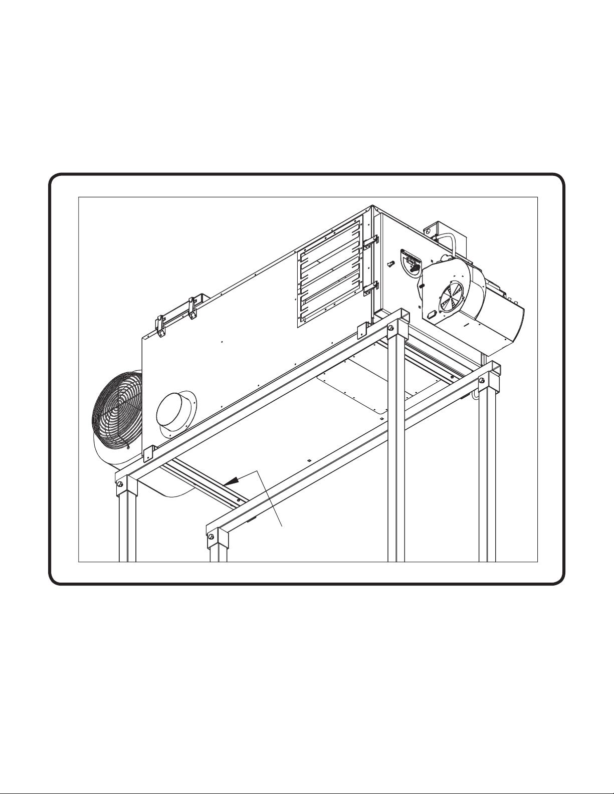
(Refer to Figure 2 which shows the area NOT to screw the Furnace Supports.)

5
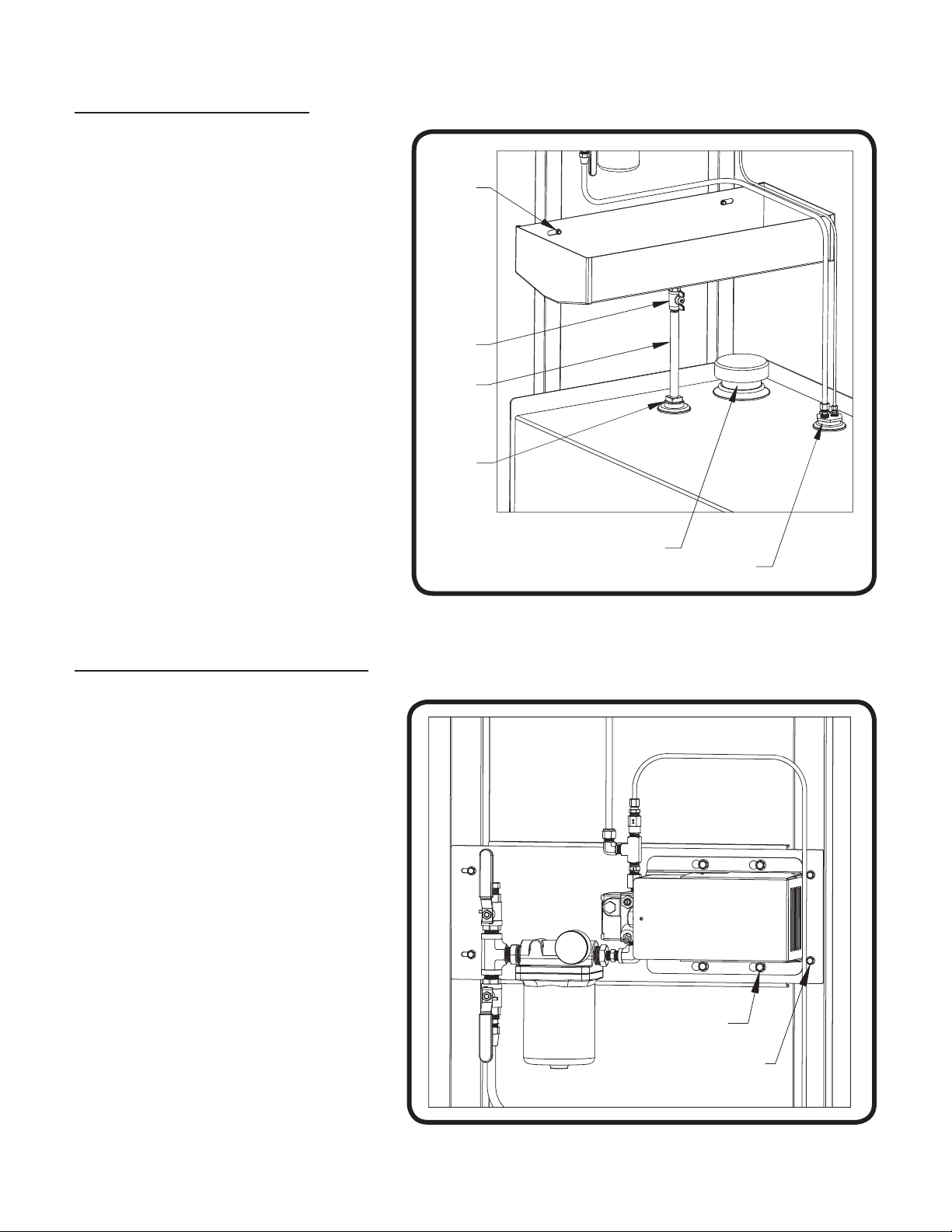
Figure 1: Tank and Support Legs Assembly
SET SCREWS
TIGHTENED (X12)
FOUR VERTICAL 2X2 POSTS
RESTING ON THE FLOOR
CE70072
FASTEN FURNACE
SUPPORTS TO THE
HEATING CENTER (X2)
HORIZONTAL
SUPPORTS (X2)
Figure 2: Area NOT to screw Furnace Supports to the base of the cabinet
FRONT OF
FURNACE
(BURNER)
NO
SCREWS
CE-140
45"
CE-180
50"
62"
CE-250
CE-330
68"
CE-140
35"
40"
CE-180
CE-250
47"
51"
CE-330
BACK OF
FURNACE
(BLOWER)
CE70150
6
Figure 3: Mounting the Pump Assembly
(1) Refer to Figure 3.
(2) Use four large self-drilling screws
to secure the pump mounting plate
to the 2” X 2” vertical posts. It is
recommended to place the pump
directly above the drain pan. This
becomes helpful when the filter is
being cleaned.
(3) Use four serrated flange cap
screws and nuts to secure the
pump to the mounting plate.
(4) Refer to the furnace Owner’s
Manual for instructions on
connecting the oil lines and wiring
the metering pump to the furnace.
Mounting the Pump Assembly:
Mounting the Drain Pan:
(1) Refer to Figure 2
(2) Assemble the drain pan, ball valve,
and pipe
(3) Install the 2” tank bushing in the
open port directly below the location
of the drain pan (on the left side
when facing the tank)
(4) Slide the pipe through the 2”
bushing and use two of the provided
large self-drilling screws to mount
the drain pan to the vertical
2” X 2” posts
HEATING CENTER ASSEMBLY
Figure 2: Mounting the Drain Pan
2" TANK
BUSHING
1/2" PIPE
BALL
VALVE
LARGE SELF
DRILLING
SCREWS
4" EMERGENCY
VENT 2" DUPLEX
FITTING
CE70070
CE70071
SERRATED
FLANGE CAP
SCREWS (X4)
LARGE SELF
DRILLING
SCREWS (X4)
7
Installing the 4” Emergency Vent:
HEATING CENTER ASSEMBLY
(1) Refer to Figure 2 for the 4” Emergency Vent location
(2) Install the 4” Emergency Vent in accordance with all state and local codes
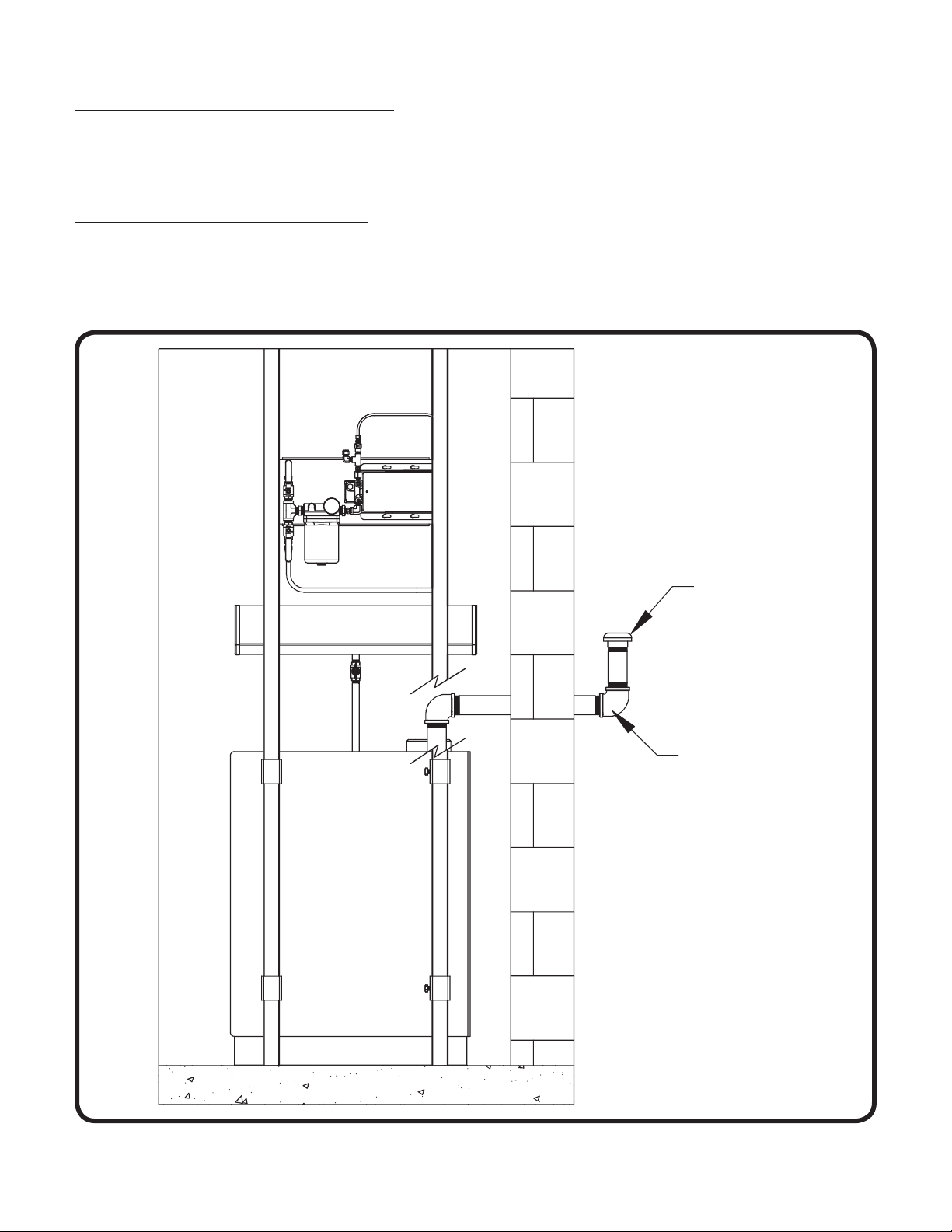
Figure 4: Installing the 2” Breather Vent
Installing the 2” Breather Vent:
(1) Refer to Figure 4
(2) Use proper 2” pipe and fittings (user supplied) to install the breather vent according to all
state and local codes
2" BREATHER
VENT
2" PIPE AND
FITTINGS
(USER SUPPLIED)
CE70074
8
MOUNTING THE FURNACE ON THE HEATING CENTER
Figure 5: Mounting the Furnace on the Heating Center
(1) Refer to Figure 5
(2) Use the self-drilling screws provided to attach the furnace to the two Furnace Support
Brackets. Review Figure 2 and keep screws out of the “no screws” area. No screws should be
in this area to keep from penetrating the bottom of the heat exchanger.
NOTE: To help keep the Heating Center stable it is recommended that braces are added from
the support legs to the nearest wall (refer to Figure 6)
REFER TO THE FURNACE OWNER’S MANUAL FOR ADDITIONAL
INSTALLATION INFORMATION
FURNACE
SUPPORTS (X2)
CE70073

9
Figure 6: Adding Braces From the Support Legs to the Wall
CE70075
BRACE SECURED
TO WALL AND
SUPPORT LEGS
(MIN. 2 PLACES)

10
HEATING CENTER EXPANDED VIEW
4
3
5
2
6
1
ITEM PART# DESCRIPTION QTY.
60023 HeatingCenterAssembly
1 50181 TankLegsandSupport 2
2 50180 TankHeatingCenter 1
3 50182 DrainPan 1
60024 HeatingCenterInstallPack 1
4 20168 PumpMountingBracket 1
5 50179 4"MaleTankEmergencyVent 1
6 50187 VentWeatherResistantBreather2" 1
20218 FurnaceSupport 2
50185 3/8CompressionX1/4MNPT90o1
50186 3/8CompressionX1/4MNPT 1
60025 HardwareBagHeatingCenter 1
80002 CopperTube1/2X7FT. 1
80003 CopperTube3/8X10FT. 1
80004 CopperTube1/4X6FT. 1
75001 LabelLargeLogo 1
70005 Owner'sManualHeatingCenter 1
Table of contents
Popular Heater manuals by other brands


Pakole
Pakole LH-30 operating manual

Dimplex
Dimplex M2GTS instructions

Reznor
Reznor RA 140 Installation/operation/maintenance manual and reference guide

Empire Heating Systems
Empire Heating Systems BF-10W-1 installation instructions

TERMOFOL
TERMOFOL TF750W Installation & operation instructions

Purmo
Purmo V10 manual


