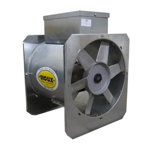
Sioux Tools S224443 Setup guide

1
Ultra Low Heater
Owner’s Parts and Instruction Manual
For the Following Heater Controls:
Thermostat
EQM Board with Relative/Humidity Sensor
Sioux Steel Company
Sioux Falls, South Dakota 57101
800-557-4689
Manual No. 224424
10-31-19/KAG
S TEEL COMPAN Y
R

2

3
Contents
Heater Models . . . . . . . . . . . . . . . . . . . . . . . . . . . . . . . . . . . . . . . . . . . . . . . . . . . . . . . . 4
Safety . . . . . . . . . . . . . . . . . . . . . . . . . . . . . . . . . . . . . . . . . . . . . . . . . . . . . . . . . . . . . . . 5-10
Heater Selection . . . . . . . . . . . . . . . . . . . . . . . . . . . . . . . . . . . . . . . . . . . . . . . . . . . . . . 11
Site Prep Installation………………… . . . . . . . . . . . . . . . . . . . . . . . . . . . . . . . . . . . 12
Centrifugal Fan Model Installation . . . . . . . . . . . . . . . . . . . . . . . . . . . . . . . . . . . . . 13-18
Triumph Fan Model Installation . . . . . . . . . . . . . . . . . . . . . . . . . . . . . . . . . . . . . . . 19-22
Thermostat Control Installation . . . . . . . . . . . . . . . . . . . . . . . . . . . . . . . . . . . . . . . . 23
Thermostat Control Model
Thermostat Operating Instructions . . . . . . . . . . . . . . . . . . . . . . . . . . . . . . . 24
Troubleshooting (Thermostat) . . . . . . . . . . . . . . . . . . . . . . . . . . . . . . . . . . . 25-27
Electrical Schematic . . . . . . . . . . . . . . . . . . . . . . . . . . . . . . . . . . . . . . . . . . . . 28-29
Electrical Layout/Components . . . . . . . . . . . . . . . . . . . . . . . . . . . . . . . . . . . 30
Plumbing Tree Layout/Components . . . . . . . . . . . . . . . . . . . . . . . . . . . . . . 31
EQM Control Model Instructions
EQM Conditioning Principles . . . . . . . . . . . . . . . . . . . . . . . . . . . . . . . . . . . 32-37
Components/Functions . . . . . . . . . . . . . . . . . . . . . . . . . . . . . . . . . . . . . . . . . 38-40
Setup and Operation . . . . . . . . . . . . . . . . . . . . . . . . . . . . . . . . . . . . . . . . . . . 41-47
Troubleshooting . . . . . . . . . . . . . . . . . . . . . . . . . . . . . . . . . . . . . . . . . . . . . . . 48-50
Electrical Schematic . . . . . . . . . . . . . . . . . . . . . . . . . . . . . . . . . . . . . . . . . . . 51
Electrical Layout/Components . . . . . . . . . . . . . . . . . . . . . . . . . . . . . . . . . . 52
Plumbing Tree Layout/Components . . . . . . . . . . . . . . . . . . . . . . . . . . . . . . 53
VFD (Vacon) . . . . . . . . . . . . . . . . . . . . . . . . . . . . . . . . . . . . . . . . . . . . . . . . . . . . . . . 54
General Maintenance . . . . . . . . . . . . . . . . . . . . . . . . . . . . . . . . . . . . . . . . . . . . . . . . . 55
Template (Thermostat) . . . . . . . . . . . . . . . . . . . . . . . . . . . . . . . . . . . . . . . . . . . . . . 57
Warranty . . . . . . . . . . . . . . . . . . . . . . . . . . . . . . . . . . . . . . . . . . . . . . . . . . . . . . . . . . . 59

4
Heater Models
PART # DESCRIPTION
Centrifugal Fan Models
S224443 7.5HP Ultra Low Heater with E M Board and Relative/Humidity Sensor
S224444 7.5HP Ultra Low Heater with Thermostat Control
S224441 10-25HP Ultra Low Heater with E M Board and Relative/Humidity Sensor
S224442 10-25HP Ultra Low Heater with Thermostat Control
Triumph Fan Models
S224443 7.5-10HP Ultra Low Heater with E M Board and Relative/Humidity Sensor
S224444 7.5-10HP Ultra Low Heater with Thermostat Control
Axial Fan Models
NA 24” Axial Ultra Low Heater with E M Board and Relative/Humidity Sensor
NA 24” Ultra Low Heater with Thermostat Control
NA 28” Axial Ultra Low Heater with E M Board and Relative/Humidity Sensor
NA 28” Ultra Low Heater with Thermostat Control

5
Safety
Read and save these instructions
General Safety Statements
Thank you for choosing a Sioux Steel Company product. It is designed to perform and serve you for many years.
It is the goal of Sioux Steel Company to improve our products whenever it is possible and practical to do so.
Sioux Steel Company reserves the right to change, improve, and modify products at any time without obligation
to make changes, improvements, and modifications on previously sold equipment.
Safety is Sioux Steel Company’s main concern for you and those who are associated with the grain handling
equipment. This manual is written to help you understand safe operating procedures, and some of the problems
that may be encountered by operator or other personnel.
It is your responsibility as owner/operator to know what requirements, hazards, and precautions exist, and to
inform all personnel associated with the equipment. Any alterations to equipment are strictly forbidden. Such
alterations may result in serious injury or death and will void any warranty on product.
This equipment shall be installed in accordance with the current installation codes and applicable regulations
which should be carefully followed in all cases. Authorities having jurisdiction should be consulted before
installation is made.
Carefully review this manual and its safety instructions before installing or operating this unit. Failure to read this
manual and its safety instructions may lead to serious injury or death. If you do not understand any part of this
manual or need assistance, contact your dealer.
Save the manual for future reference by personnel operating or maintaining the unit.
THIS MANUAL DESCRIBES THE OPERATION OF THE ULTRA LOW HEATER. THIS PRODUCT
IS IDEAL FOR THE CONDITIONING OF CORN, SOYBEANS, AND OTHER SELECT GRAINS. ANY
OTHER USE IS CONSIDERED A MISUSE OF THE PRODUCT.

6
Safety
Recognize the Safety Alert Symbol
The above symbol means “Attention! Be Alert! Your Personal Safety Is Involved!” Note this symbol in instructions for
important issues concerning your personal safety. Read each message carefully to avoid personal injury or death.
Follow Machine Safety Signs & Messages
Observe safe operating practices. Carefully read this manual and all safety signs on your equipment. Safety signs must be
kept in good condition. Replace missing or damaged safety decals or shields. Safety decals and shields are available free of
charge from Sioux Steel Company, 196 ½ E. 6
th
St., Sioux Falls, SD 57101-1265.
Learn how to use controls and operate equipment. Do not let anyone operate unit (especially youth) without thorough training
of basic operating and safety procedures.
Make no unauthorized modifications to equipment. Modifications may endanger function and/or safety of unit. Periodically
check all mechanical and electrical components. Keep unit in good working condition.
Practice Safe Maintenance
Read and understand correct service procedures before operating. Keep area clean and dry to prevent accidents. Machine
should never be lubricated, serviced, or adjusted while it is in operation. Hands, feet and clothing must be kept away from all
moving parts. Keep all parts in good condition and properly installed. Fix any damage immediately. Qualified service
personnel should replace worn or broken parts. Any built-up grease, oil, and debris around machine should be removed.
Emergencies - Know What To Do
A first aid kit should be made readily available.
In the event of fire, a fire extinguisher should be at hand.
Have emergency numbers near your telephone for doctors, emergency medical squad, ambulance service, hospital, and fire
department and also have written directions to your location.
Wear Protective Clothing
•Clothing- Avoid baggy clothes to avoid catching on moving parts.
•Hearing Protection- When high noise levels are encountered, ear plugs or muffs should be used.
•Eye Protection- Safety glasses should be worn at all times to protect eye from debris.
•Gloves- Always wear gloves to protect hands from sharp edges.
•Steel Toe Shoes- Appropriate shoes should be worn to protect toes from falling debris.
•Respirator- In order to prevent breathing toxic fumes or dust, a respirator may be needed.
•Hard Hat- Appropriate headwear should be worn to protect head from falling debris.
•Fall Protection- Appropriate fall protection should be worn when working at elevations greater than six (6)
feet.
Signal Word Color Potential Injury or Damage Likelihood of Occurrence
DANGER Red
Severe
Indicates an imminently hazardous situation which, if not
avoided will result in death or serious injury.
W LL Occur
if Warning is ignored
WARN NG Orange
Severe
Indicates a hazardous situation which, if not avoided, will
result in death or serious injury.
COULD Occur
if Warning is ignored
CAUT ON Yellow
Minor
Indicates a hazardous situation which, if not avoided, will
result in minor or moderate injury.
W LL or COULD Occur
if Warning is ignored
NOT CE
Blue
or
Yellow
None
Indicates an important message or instruction not related
to personal injury.
N/A
SAFETY ALERT SIGNAL WORDS

7
Safety
Warning: To reduce the risk of fire, electric shock, or injury to persons, observe the following:
1. Use this unit only in the manner intended by the manufacturer. If you have any questions, contact the
manufacturer.
2. Before servicing or cleaning unit, switch power off at service panel and lock the service disconnecting
means to prevent power from being switched on accidentally. When the service disconnecting means
cannot be locked, securely fasten a prominent warning device, such as a tag, to the service panel.
3. Installation work and electrical wiring must be done by a qualified person(s) in accordance with all
applicable codes and standards, including fire-rated construction.
Warning: To prevent explosion or fire:
1. Carefully review the operator’s manual.
2. Clean under floor, as fines may cause a bin fire.
3. Do not use to exhaust hazardous or explosive material and vapors.
4. Disconnect and lock out all power sources before servicing equipment.
Warning: Keep clear of all moving parts
1. Keep people (ESPECIALLY YOUTH) away from equipment, particularly during operation.
2. Keep away from all moving parts. Entanglement can cause serious injury or death.
3. Keep inlet guard in place and in good working condition.
4. If fan is wired for suction, outlet must be shielded to protect an individual from moving parts.
Failure to follow the above precautions may cause serious injury or death.
Caution: To avoid electrocution, all equipment must be properly wired and grounded according to electrical
codes. Have unit wired by a qualified electrician.
Have your electrician install a main power disconnect switch capable of being locked only in the Off position.
Mark disconnect clearly as to the equipment it operates. Always Lock Out main power disconnect switch
whenever equipment is not in use or when servicing the unit.

8
Safety
Danger: Never enter bin, unless all power is locked off and another person is present. Rotating augers can kill or
dismember!
Danger: Flowing grain may trap and suffocate. If you enter a bin of flowing grain you can be completely
submerged in grain in seconds. Failure to heed may cause serious injury or death.
Warning: Heater must be electrically interlocked with fan. Never operate heater without airflow. Failure to do so
may cause serious injury or death.
Caution: To avoid personal injury, frequently inspect all mechanical and electrical components. Lock Out all
power whenever servicing equipment. Replace and/or repair worn parts. Be sure all electrical wire is in good
condition.
Danger: Disconnect electricity before inspecting or servicing. Lock out all power and have another person
present. Always lock off all power and check with voltage meter before servicing. Failure to do so may cause
serious injury or death.

9
Safety
Safety Decal Locations
Safety decals and shields are mounted whenever possible at factory. Please check that all decals are in place
according to these drawings and in good legible condition. To order replacement decals or shields (NO
CHARGE) contact your dealer or Sioux Steel Company, 196 ½ E. 6
th
St., Sioux Falls, SD 57101-1265. Please
specify serial number.
Important! The following safety decals should be mounted on your equipment as shown below. If suggested
locations are not clearly visible, place safety decals in a more suitable area. Never cover up any existing safety
decals.
Make sure location area for decal is free from grease, oil, and dirt. Remove backing from decal and place in
proper position.
1. Warning- 165232
2. Danger- 169910
(Safe Operation Decal)
(Service Door Decal)
3. Warning- 169908
(Vapor Propane)
1
2
3

10
Safety
Safety- In Case of Fire Instructions
Important:
To maintain grain quality and avoid risk of bin fire, drying temperature should not exceed 130°F for in-bin
stir drying of corn, or 180°F for in-bin continuous-flow system. Lower temperature may be required
depending upon drying conditions.
Keep areas beneath perforated floor clean of all fines and foreign material.
If Fire is suspected:
1. Shut off gas at supply tank and heater. Shut off fan.
2. Call Fire Department.
3. Seal fan inlet and any other openings to smother fire.
4. Remove fan and heater from transition. Sand-bag transition opening. If possible, flood bottom of bin (plenum)
with water to a depth of 4” above perforated floor. This will protect steel floor supports and may extinguish
fire, depending upon it’s location. If fire is located higher in bin, insert a long pipe with small holes through
bin wall and into grain to direct water at source of fire.
5. Unload bin. “All Grain Must Be Removed From Bin to Reach Point of Fire”. It should not be necessary to
cut large hole in bin to remove grain.
Note: Grain may smolder for days. Do not restart fan in hope that fire has gone out, unless all grain has been
removed from bin.
Note: It is important that grain be screened before going into bin to avoid formation of fines and trash. Cleaned
grain is less likely to develop hot spots.

11
Heater Selection
Determine the Right Size Fan for Your Bin Size First
Warning! Determining the correct size fan for the size of the bin, type of grain and needs, is the key to
successful drying. Your heater selection only needs to match your fan size, fuel source at hand, and type of heater
controls desired. Responsibility for the Grain Condition is Yours!
Warning! Incorrect fan size will cause your heater to not preform to your expectations. Too much static pressure
is the leading cause of poor heat, burnt wiring in the chamber, and may cause your chamber to burn up. Oversized
fans for a bin will cause as much damage as undersize.
Note: Provide one square foot roof opening per thousand cfm fan capacity.
Fuel Source: Ultra low temp heater will use vapor propane. For LP fuel line, use 5/8” OD type K copper tubing
or ½” schedule 80 black steel pipe. Use 3-5 foot of flexible LP hose between fuel line and heater. Before
connecting to heater, purge gas line to blow out any dirt in pipe. When using vapor heater, connect at regulator.
LPG Tank Size (gallons) for Vapor Withdrawal*
BTU/HR**
LOWEST AVERAGE 24-HR OUTDOOR TEMPERATURE (F)
32 20 10 0 -10 -20 -30
125,000 115 115 115 250 250 400 600
250,000 250 25 250 400 500 1000 1500
375,000 300 400 500 500 1000 1500 2500
500,000 400 500 750 1000 1200 2000 3500
750,000 750 1000 1500 2000 2500 4000 5000
Source: LP Gas Handbook of Technical Data (Fisher Controls Co.)
*Tank is assumed to be half full
** Average rate in 8hr period.

12
Site Prep Installation
For Operation with Propane Vapor
Danger: These units operate with flammable and explosive gases, improper installation, operation, or
maintenance can create potential danger. Read all instructions carefully, and obey all cautions and
warnings. Failure to do so could result in serious bodily injury or property damage.
Shipping, Receiving, and Inspection
Review heater model number, confirming this is the model you ordered. Contact your dealer immediately if
otherwise. All cardboard cartons are shipped attached to heater, with power cord installed. Inspect heater for
damage, noting any found on freight bill.
Preparing Site For Installation
Warning! Be sure to review previous pages on warnings. Installation should be performed only by a qualified
dealer, who is experienced and familiar with grain drying equipment, and with local codes, laws, and ordinances
regulation gas and electrical installations. Improper installation could result in serious bodily injury or property
damage.
Before installing heater and controls- your locale gas company needs to review your site and read the following
information regarding your needs for a correct, safe installation, and operating future.
Heater Using Propane Vapor
A 1,000 gallon storage tank should provide adequate vaporization to ignite the heater within its capacities. The
heater should not be used if the tank is less than 20% full. The storage tank should be equipped with a propane
regulator with an outlet pressure of range of 0 to 60 psi, set and locked at 30 psi.
If the tank is within 50 feet of the heater, 5/8” OD, type K copper tubing, or ½” schedule 80 black pipe should be
used for the gas supply line from the vapor regulator on the tank to within 3 feet of the heater, if the tank is more
than 50 feet away, use 7/8” OD type K copper tubing.
Caution: The gas storage tank should be at least 25 feet from the heater. Local ordinances may require
further distances.
A high pressure 3 to 5 foot flexible hose for use with LP gas should be used to connect gas supply line directly to
heater regulator.
The gas supply line should be buried at least 6” below the ground.

13
Centrifugal Fan Model Installation
1. Remove existing fan guard.
Also remove hardware where
indicated by the Letter “A”
for mounting of Burner
Assembly. Save 5/16” Fender
Washers and Bolts for future use
2. Mount “Cent Mnt” (224416) onto
Burner Ass’y (224314) as shown
utilizing ¼”x ¾” Hex bolts (154003)
and ¼” Nylock Nut (157388). Leave
hardware slightly loose for final adjustments.
3. Mount Assembly from Step 2 to fan housing
in position shown. Utilize washers and bolts
from Step 1. Verify burner is centered over
opening. Finish tightening ¼” hardware from
Step 2 after final adjustments for positioning
of Burner Assembly is made. Note: Assembly
is designed to fit a 26.5” to 35.25” bolt
hole pattern diameter.

14
Centrifugal Fan Model Installation
4. Assemble Control Box Mounts (224414) to base of Control Box as shown below utilizing ¼”x ¾” Hex
bolts (154003) , ¼” Washers (13368), and ¼” Nylock Nut (157388).
5. For EQM version of heaters only (Heater Models S224441 and S224443). Proceed to next step for
Thermostat versions (Heater Models S224442 and S224444)
a. Install Temperature and Relative Humidity Sensor inside control box (sensor will be found inside
box). Sensor will need to be inserted in small hole found in bottom of box. The Sensor Filter,
found at end of sensor, must be removed prior in insertion and then re-attached. Mount sensor to
bottom of box using the three holes and screw provided.
Remove Sensor Filter Inset Sensor & Reattach Filter Mount Sensor
b. Position Control Box Assembly on top of fan as shown and mark location of end of sensor on
scroll of fan housing. Drill 7/8” hole into scroll of housing for sensor. Control Box Assembly will
now be able to mount to top of fan.

15
Centrifugal Fan Model Installation
6. Position Control Box Assembly on top of fan
as shown and mount to top of fan housing
utilizing ¼” x 1.25” Drill Screws (157630).
7. Drill a 1” hole in scroll of fan housing where indicated for High Limit Switch (2 x 4 box). Remove cover
from Hi Limit Box and mount box to fan housing by positioning Hi Limit into hole and mounting box to
housing with #10 x .75” Drill Screws where indicated. Reinstall cover on Hi Limit Box.
8. Seal Hi Limit Switch and Temperature and Relative Humidity Sensor (if equipped with heater) holes with
silicone caulk.

16
Centrifugal Fan Model Installation
9. Connect 45° elbow (224420) and
hose (224436) to Burner Assembly
as shown using Gas Rated Teflon
Tape (208980). Position elbow to allow
Hose to easily connect to the Plumbing
Tree Connection. Note: Support Burner
Assembly pipe when connecting elbow
and hose to avoid twisting of assembly.
10. Depending on heater package ordered, the heater will come with either a 28” Guard (224160) or a 24”
Guard (224161).
a. The 28” Guard will fit approximately a 29.75” bolt hole pattern diameter.
b. The 24” Guard will fit approximately a 27.75” bolt hole pattern diameter.
To increase the bolt hole pattern diameter (4) Guard Mount (224415) can be installed onto the guard as
shown below utilizing 5/16” x 1” Hex bolts (157540), 5/16” Fender Washers (208197), and 5/16”
Nylock Nut (157540).
c. The 28” Guard, with Guard Mounts, will fit approximately up to a 34.5” bolt hole pattern
diameter.
d. The 24” Guard, with Guard Mounts, will fit approximately up to a 32.5” bolt hole pattern
diameter.
Measure bolt hole pattern diameter of fan as shown below to determine if Guard mounts are needed. If
needed, install onto guard as shown.

17
Centrifugal Fan Model Installation
11. Mount Heater Guard onto fan as shown
utilizing 5/16”washers and bolts from
Step 1. After Guard is installed insert
and tighten remaining 5/16” washer and
bolts in their original holes from Step 1.
12. Connect rubber LP gas hose from Burner Heater Assembly to plumbing tree found on control box. Also
connect flame rod wire and ground wire to Flame/Sense rod on burner assembly.
13. Check Gas Line for leaks with soapy water.
14. For EQM version of heaters (Heater Models S224441 and S224443), if the optional Headspace
Temperature/Relative Humidity Sensor was provided, install at this time. Skip step if heater is a
Thermostat version (Heater Models S224442 and S224444).
a. Sensor will be mounted to the bin roof above where grain is present. To install, this requires
drilling a 7/8” hole for the probe and using 3 small self-drilling sheet metal screws (customer
supplied) to mount to roof. Seal hole in roof with Silicone Caulk.
b. Sensor will need to be wired into heater control box using 3 conductor 18awg shielded wire and
any necessary conduit and fitting (customer supplied). Note: ½” knock out plugged hole in
bottom of control box for Headspace Sensor. See EQM Control Model Electrical Schematic
(pg 51) on how to connect Sensor to EQM Board in control box.

18
Centrifugal Fan Model Installation
15. For Thermostat version of heaters (Heater Models S224442 and S224444) Install Thermostat Control at
this time. See Thermostat Installation Section of manual for instructions (pg 23). Skip step if heater is a
EQM version (Heater Models S224441 and S224443).
16. Connect incoming 120vac power to heater controls according to specific heater model schematic.
Note: Heater must be interlocked to fan starter box or VFD.
a. For EQM Version (Heater Models S224441 and S224443) schematic see EQM Control Model
Electrical Schematic (pg 51)
b. For Thermostat Version (Heater Models S224442 and S224444) schematic see Thermostat
Control Model Electrical Schematic (pg 28-29)
17. For operating instructions see either EQM Control Model (Heater Models S224441 and S224443) pages
32-47 or Thermostat Control Model (Heater Models S224442 and S224444) pages 24 sections of this
manual.

19
TRIUMPH FAN MODEL INSTALLATION
1. Remove existing fan guard.
Save 5/16” Fender Washers
and Bolts for future use.
2. Drill 9/32” holes on top and inlet side of fan where indicated by dimples.
a. For EQM version of heater (Heater Model S224443), that includes a Temperature Relative
Humidity Sensor, a 7/8” hole will need to be drill where indicated on top of fan for the sensor.
Note: Only drill 7/8’ hole if heater has a Temperature Relative Humidity Sensor.
3. Mount “Triumph Mnt” (224316) onto
Burner Ass’y (224314) as shown utilizing
¼”x ¾” Hex bolts (154003) and ¼” Nylock
Nut (157388). Leave hardware slightly
loose for final adjustments.

20
TRIUMPH FAN MODEL INSTALLATION
4. Mount Assembly from Step 3 to fan
housing in position shown. Utilize
washers and bolts from Step 1. Verify
burner is centered over opening. Finish
tightening ¼” hardware from Step 3 after
final adjustments for positioning of
Burner Assembly is made. Insert and
tighten remaining 5/16” washer and bolts
in their original holes from Step 1.
5. For EQM version of heater only (Heater Model S224443). Proceed to next step for Thermostat version
(Heater Model S224444).
a. Install Temperature and Relative Humidity Sensor inside control box (sensor will be found inside
box). Sensor will need to be inserted in small hole found in bottom of box. The Sensor Filter,
found at end of sensor, must be removed prior in insertion and then re-attached. Mount sensor to
bottom of box using the three holes and screw provided.
Remove Sensor Filter Inset Sensor & Reattach Filter Mount Sensor
6. Position Control Box Assembly on top
of fan as shown aligning mounting holes
of control box base with 9/32” holes drilled
previously. If control box is equipped with
sensor, insert sensor in 7/8” hole. Secure
control box to fan housing using (4x) 5/16”
x ¾” Self-Forming Screws.
Table of contents
Other Sioux Tools Heater manuals
Popular Heater manuals by other brands

Berko
Berko FRA series Installation and maintenance instructions

Singer
Singer SFH-200CBA instruction manual

Carbon Heater
Carbon Heater DeskClimate Assembly and operating instructions

Global
Global 246726 user manual

Strend Pro
Strend Pro DL01-D TURBO instruction manual

TPI
TPI E3313RP installation instructions