Safety information
This manual describes installation and service procedures
for implementation by specialists.
This appliance can be used by children
aged from 8 years and above and per-
sons with reduced physical, sensory or
mental capabilities or lack of experience
and knowledge if they have been given
supervision or instruction concerning use
of the appliance in a safe way and under-
stand the hazards involved. Children shall
not play with the appliance. Cleaning
and user maintenance shall not be made
by children without supervision.
Rights to make any design or technical
modifications are reserved.
©NIBE 2017.
Symbols
NOTE
This symbol indicates danger to person or ma-
chine .
Caution
This symbol indicates important information
about what you should observe when maintain-
ing your installation.
TIP
This symbol indicates tips on how to facilitate
using the product.
Marking
The CE mark is obligatory for most products sold
in the EU, regardless of where they are made.
CE
Classification of enclosure of electro-technical
equipment.
IP21
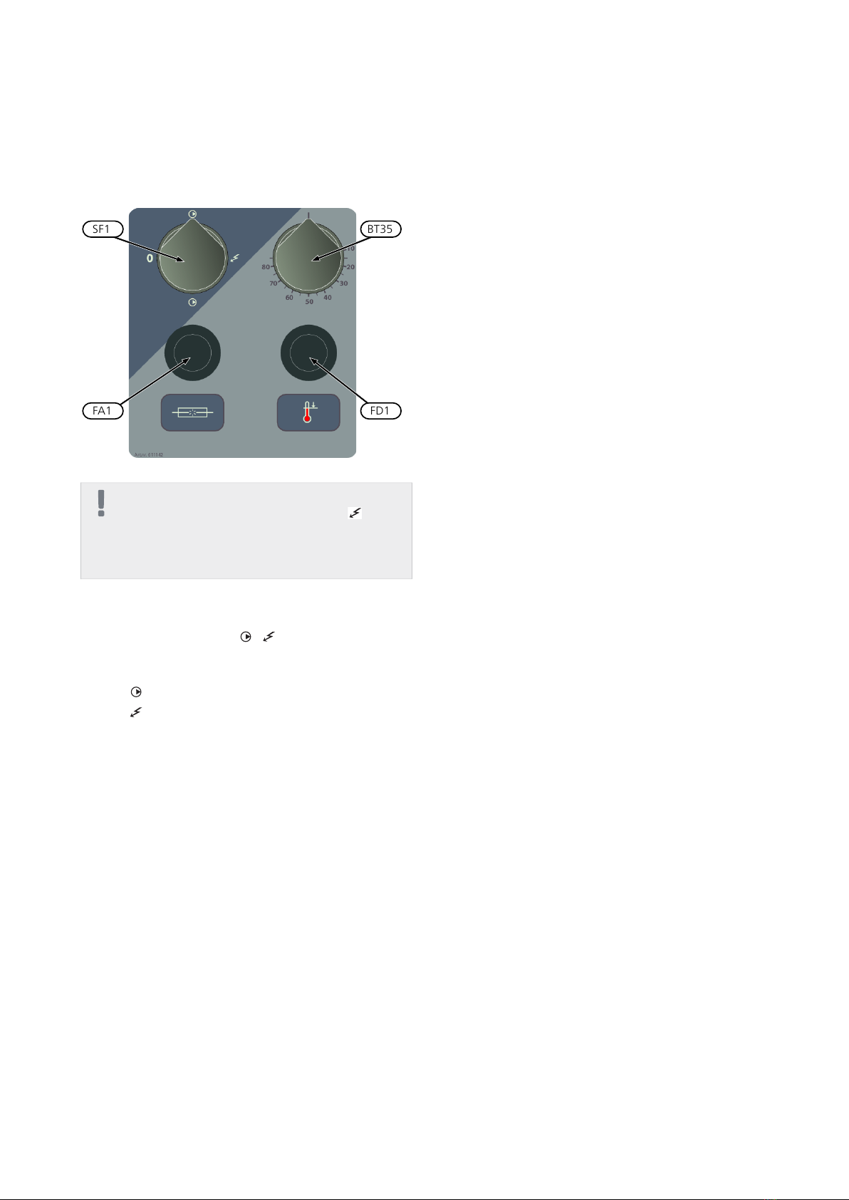
Serial number
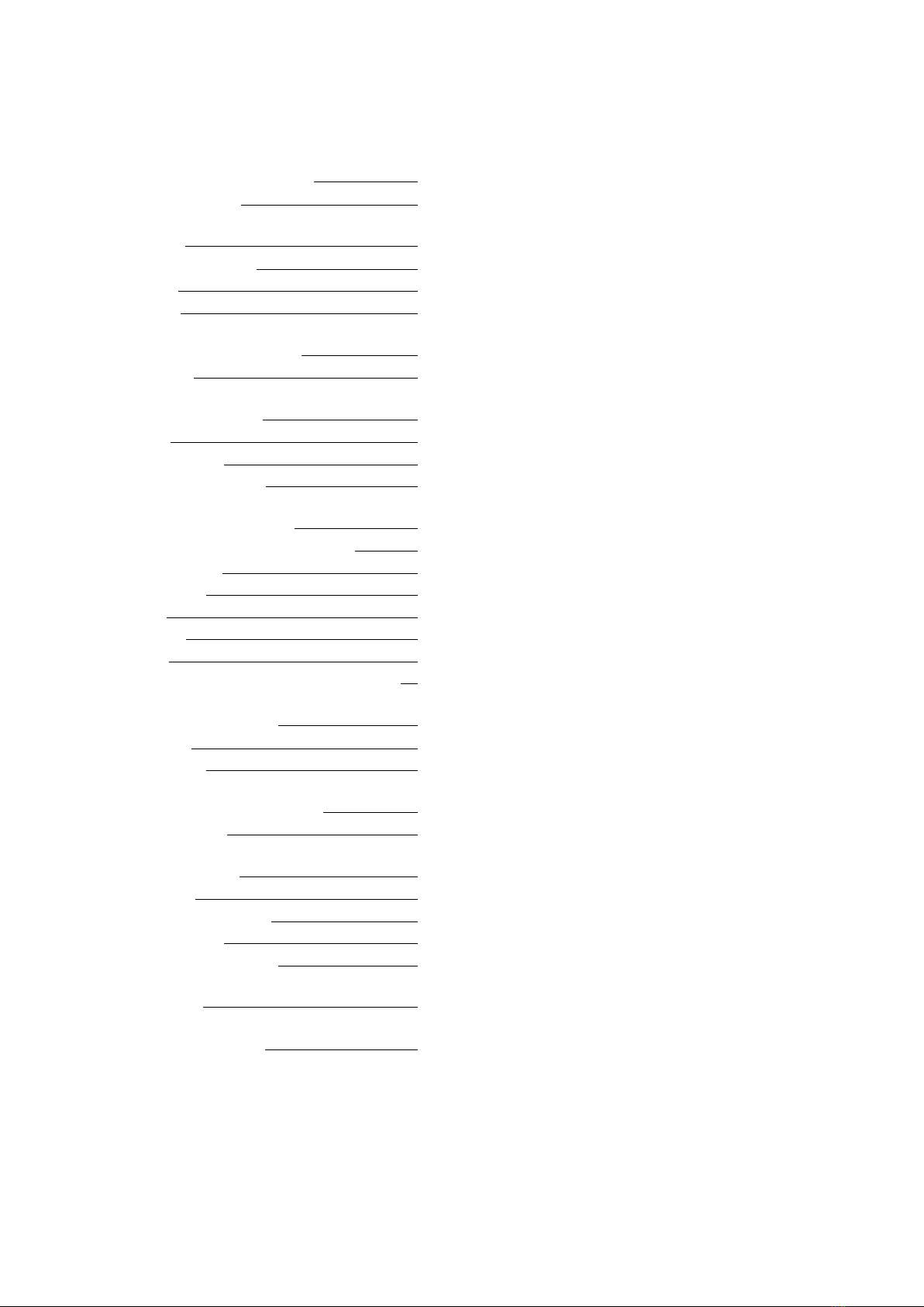
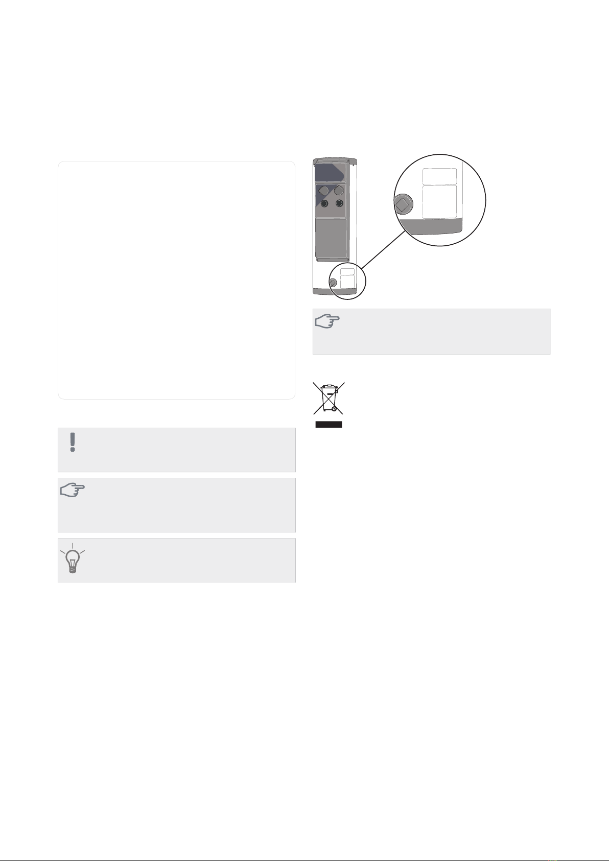
The serial number can be found at the bottom right of
ELK 213.
Caution
You need the product's (14 digit) serial number
for servicing and support.
Recovery
Leave the disposal of the packaging to the in-
staller who installed the product or to special
waste stations.
Do not dispose of used products with normal
household waste. It must be disposed of at a
special waste station or dealer who provides this type of
service.
Improper disposal of the product by the user results in
administrative penalties in accordance with current legis-
lation.
Country specific information
Installer manual
This installer manual must be left with the customer.
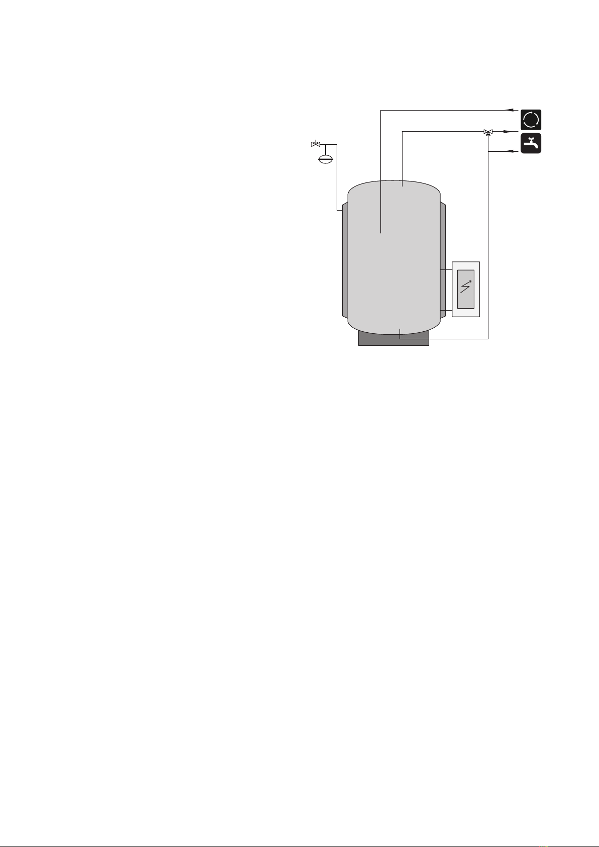
Immersion heaterChapter 1 | Important information4
1 Important information