Clean Logix FBHS-MR User manual
USER
MANUAL
English (Original Instrucons)
Updated: 05/12/20
MODEL:
FBHS-MR
Foot Bath Hand Sanizer
FBHS Manual Page 2 of 23 Updated: 05/12/20
USER MANUAL: FBHS-MR
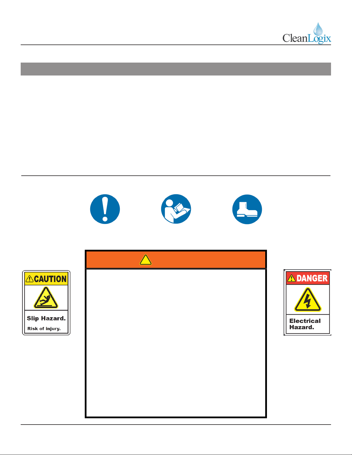
READ ALL INSTRUCTIONS BEFORE OPERATING EQUIPMENT
!
WARNING:
1. All personnel using this unit must be familiar with
the informaon contained in this manual. Follow all
installaon and maintenance instrucons.
2. Always wear appropriate footwear. Secure or remove
loose items on footwear.
3. Ensure solid foong when operang the unit.
4. Avoid contact of chemicals with skin and eyes. If contact
occurs, see MSDS sheet for further rst aid measures.
5. Follow safety instrucons of chemical manufacturer
(MSDS).
6. Always follow plant and OSHA guidelines about the use
of equipment.
7. Disconnect power before servicing equipment.
8. Always follow safety precauons and obey warning
labels. Failure to do so could result in injury or death.
Table of Contents
System Requirements
Installaon
Physical Set-Up
Plumbing Connecons
Priming
Trac Direcon
Operaon
03
04
06
07
07
08
Cleaning
Maintenance
Troubleshoong
Appendices
Parts Callouts
Electrical Schemacs
P&I Diagram
09
10
12
16
22
23

FBHS Manual Page 3 of 23 Updated: 05/12/20
USER MANUAL: FBHS-MR
READ ALL INSTRUCTIONS BEFORE OPERATING EQUIPMENT
Water Supply
• Flow: 5 GPM (3.8L/m) minimum*
• Pressure: 50-60 psi (207-414 kPa)**
• Max Temperature: 70⁰F (4-38⁰C)
3/8" supply piping size recommended
*Minimum pressure must be maintained during
specied water ow!
**For consistent operaon of spray nozzles, a water
pressure regulator and lter is recommended.
Electrical
• 120 VAC Single Phase
• 60 Hz 15 Amps
• Supplied with 8 . power cable with NEMA 5-15P
plug
The FBHS, Foot Bath and Hand Sanizer, applies a
ne mist spray onto the hands through 16 an-drip
nozzles. Concentrated sanizer and water are pre-
mixed in the onboard batch tank before it is applied
to the hands. Dual sensors detect travel direcon
and acvate hand spray when the user enters the
producon area. “Watchdog” mers are programmed
into the system to prevent excessive water loss in the
event of sensor failure. Level switches in both the
foot bath and batch tank detect the liquid level and
automacally replenish as necessary.
Overview
NOTE: Back ow prevenon must be installed
in the water line to this unit. Check local
codes to ensure proper installaon.
System Requirements
!
WARNING:
DO NOT EXCEED maximum water
temperature! Damage can result.
• Construcon: 304L stainless steel (frame). LDPE,
Polypropylene, Fiberglass reinforced Polyester (grate).
• Weight: 200 lb (90.72 kg)
• Dimensions: 48.5" x 47.5" x 46"
(123.2 x 120.6 x 116.8 cm)
• Water Consumpon: 1.5 GPM (3.8 L/m)
• Preset Chemical Diluon Rao: 1:400*
Cleaning Methods
See pages 8 for disassembly and cleaning instrucons.
For chemistry recommendaons:
Specicaons
*NOTE: Unit tested at 70°F using water with
50 psi injector inlet pressure.
!
WARNING:
DO NOT use ammable liquids (i.e. alcohol
based soluons or similar) without diluon.
Use Case Chemical Type
Organic Soils Chlorinated Alkaline or Alkaline based
foaming cleaner
Mineral Buildup Acid based foaming cleaner
NOTE: Chemistry used must be compable
with materials of construcon (listed above).
FBHS Manual Page 4 of 23 Updated: 05/12/20
USER MANUAL: FBHS-MR
READ ALL INSTRUCTIONS BEFORE OPERATING EQUIPMENT
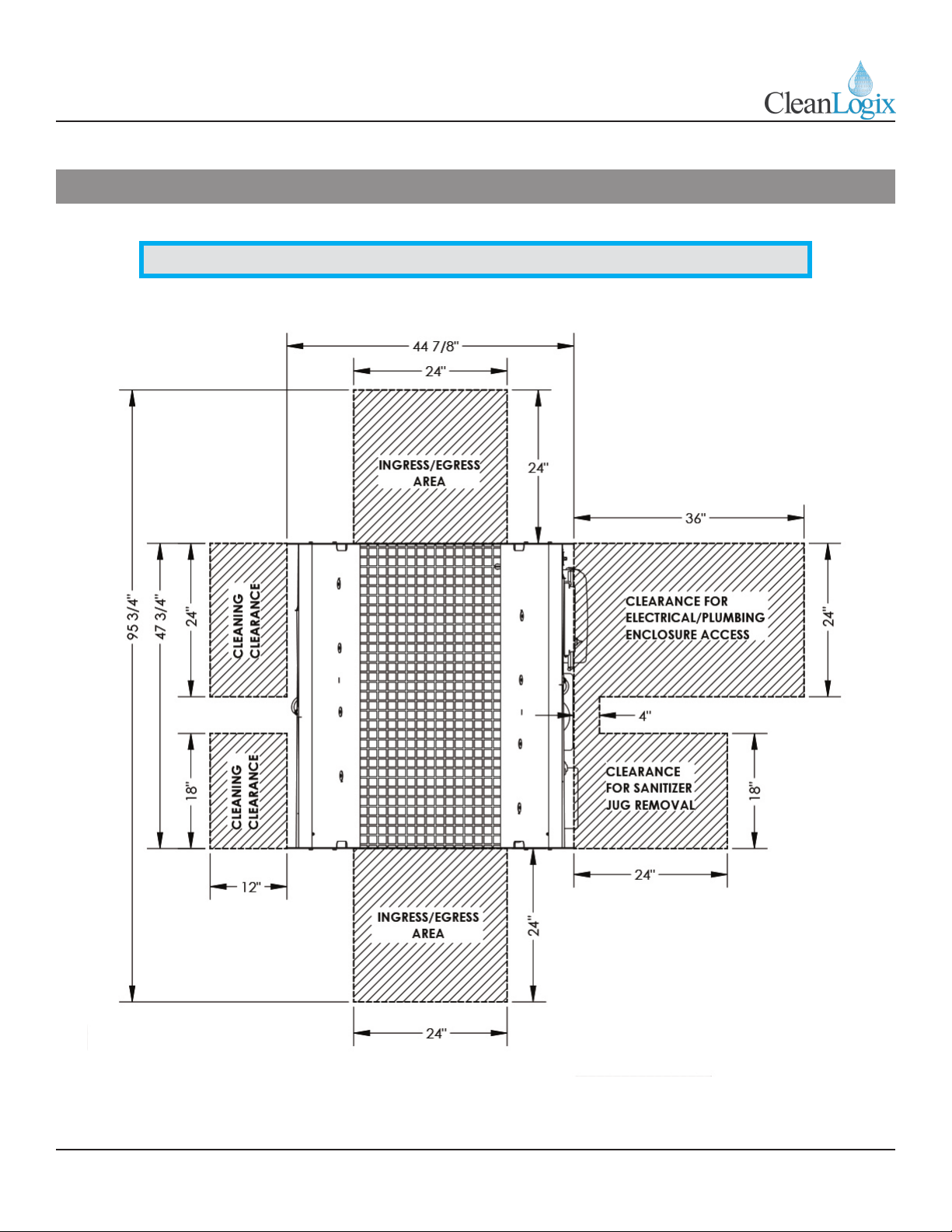
NOTE: For xed installaons, area in front of electrical panel must be clear at least 36"
Installaon

FBHS Manual Page 5 of 23 Updated: 05/12/20
USER MANUAL: FBHS-MR
READ ALL INSTRUCTIONS BEFORE OPERATING EQUIPMENT
NOTE: Trac ow direcon
can be reversed by swapping
wires on inputs I-00 and I-001 of
microcontroller (see electrical
schemac for more informaon).
Installaon
NOTE: Model -MR (Manual Refreash Foot Bath) is for locaons which do not have a
dedicated drain. Foot bath level is maintained by oat switch and is only refreshed
with new sanizer if and when level drops to a point which acvates oat switch.

FBHS Manual Page 6 of 23 Updated: 05/12/20
USER MANUAL: FBHS-MR
READ ALL INSTRUCTIONS BEFORE OPERATING EQUIPMENT
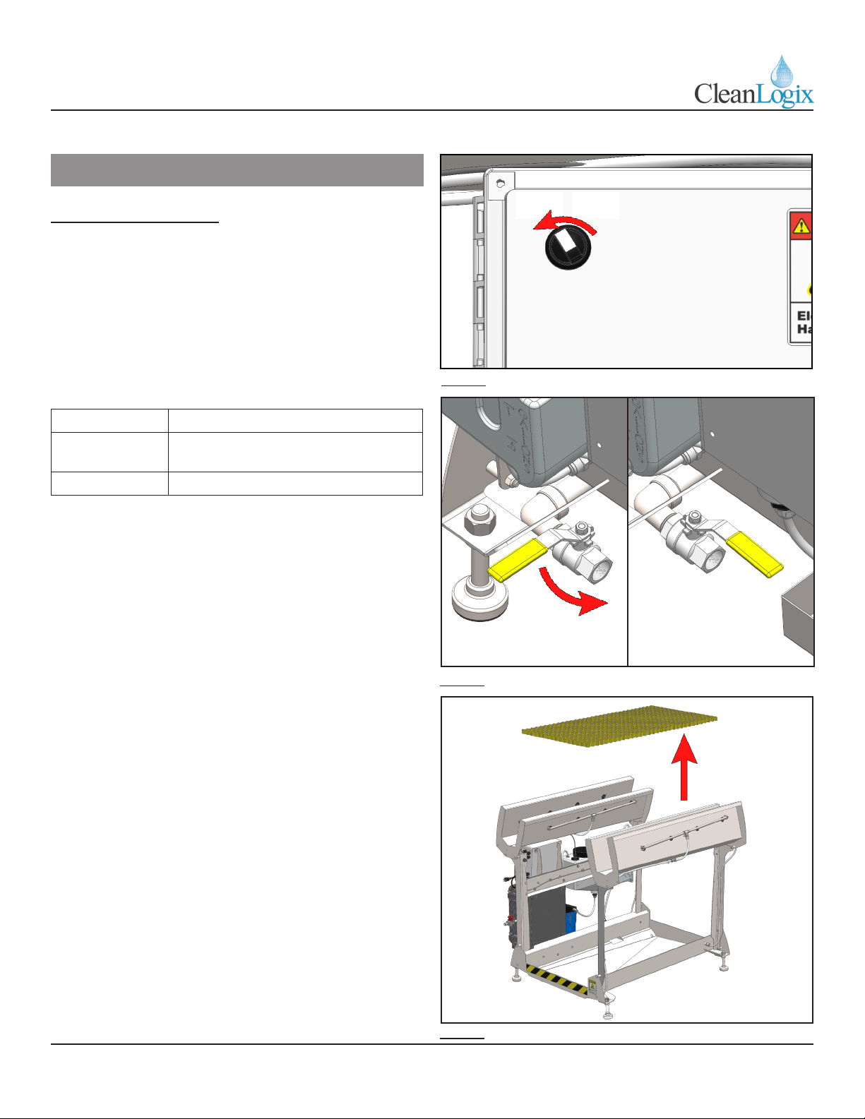
Physical Set Up:
1. Set unit in desired locaon.
2. Aspects to consider when deciding on placement:
• Clearance for general use
• Locaon of drain
• Emergency exit paths or egress
• Access to control box
• Connecons for water, electricity, and air
3. Use a level to make sure the unit is stable and
leveled in all direcons [Figure 6.1].
4. Connect unit to electrical supply.
Plumbing Connecons:
1. Using 1/2" LDPE tubing or similar, connect water
to the unit's push to connect ng [Figure 6.2]
2. Using 3/8" LDPE tubing or similar, connect air to
the unit [Figure 6.2].
3. Fill chemical jug with sanizer product and
connect sucon line (label jug for idencaon).
4. If necessary, adjust the diluon rao by selecng
an appropriate metering p (included) and test.
• The unit is pre-congured for a 1:400 diluon
rao.
• The smallest metering p is a yellow p with a
small tube aached. This tube can be trimmed
to alter the diluon rao. [Figure 6.3]
Installaon
NOTE: To move the unit use a pallet jack or a
hi-lo to li from the boom. Pad the forks to
protect the nish. Fig. 6.1: Level and stabilize unit using a leveling device
Capillary
Tube
Addional
Metering Tips
Fig. 6.3: Metering Tips and Capillary Tube
Fig. 6.2: Water and air inlets
Air (3/8")
Water (1/2")
FBHS Manual Page 7 of 23 Updated: 05/12/20
USER MANUAL: FBHS-MR
READ ALL INSTRUCTIONS BEFORE OPERATING EQUIPMENT
Installaon
Plumbing Connecons:
• Full length capillary tube results in a diluon
rao of approximately 1:670 at 30-50 psi
water inlet pressure.
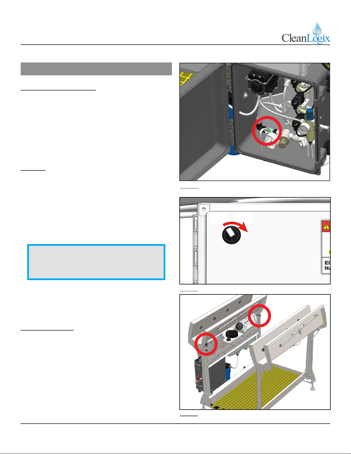
• When complete, re-connect soluon lines to
green hose barb of the Venturi Injector located
in plumbing enclosure [Figure 7.1].
Priming
1. Turn switch on control box to ON posion [Figure
7.2].
2. Turn the red-handled compressed air relief valve
on the air inlet to SUP.
3. Prime hand spray system by acvang sensor
at front of unit (either by stepping in front of or
waving your hand) unl soluon begins to spray.
4. Use appropriate means (traon or other) to
ensure sanizer is being mixed into hand spray
and foot bath at the correct ppm.
Trac Direcon
• The hand spray is designed to acvate only when
users are entering the unit from one end. The
default trac direcon is shown in the previous
secon.
• The trac direcon can be changed if desired by
switching the two black wires in terminals I-00
and I-01 on the micro controller (see electrical
schemac for more informaon).
Fig. 7.1: Venturi DEMA Rocket Injector locaon
Fig. 7.2: Controller power switch
OFF ON
Fig. 7.3: Acvaon sensor locaons
NOTE: If the lter cartridge is empty, it may
take 10-20 acvaons of the hand spray
before the lter becomes saturated and the
pump primes.

FBHS Manual Page 8 of 23 Updated: 05/12/20
USER MANUAL: FBHS-MR
READ ALL INSTRUCTIONS BEFORE OPERATING EQUIPMENT
1. Make sure the drain valve is closed [Figure 8.1]
2. Turn the power switch to “ON” [Figure 8.2]
• If the batch tank is low or empty, it should
begin to ll.
• If the foot bath is low or empty, it will begin to
ll aer the batch tank is full.
3. Make sure the red handled air-shuto valve is
turned to “SUP”.
4. Once the foot bath and batch tank are full, the
user may step into the unit.
• The hand spray will acvate as soon as the
user steps into the unit, and will stop one
second aer they step o.
Operaon
NOTE: The hand spray is designed to acvate
only in one trac ow direcon [Figure 8.3].
Flow direcon can be altered if necessary (see
page 7 for more informaon).
Fig. 8.1: Drain valve open (le) to close (right)
Fig. 8.2: Controller power switch
OFF ON
Fig. 8.3: Sensor beam and trac direcon
Sensor
Beam
Trac
Direcon
FBHS Manual Page 9 of 23 Updated: 05/12/20
USER MANUAL: FBHS-MR
READ ALL INSTRUCTIONS BEFORE OPERATING EQUIPMENT
Cleaning Instrucons
1. Turn the power switch to “OFF” [Figure 9.1].
2. Open the drain valve to drain the foot bath [Figure
9.1].
3. Use a cleaner that will not aack 304 stainless
steel or any of the materials listed in the unit
specicaons.
Use Case Chemical Type
Organic Soils Chlorinated Alkaline or Alkaline based
foaming cleaner
Mineral Buildup Acid based foaming cleaner
4. Avoid direct water spray around the control boxes
and wiring entering/exing the control boxes.
5. If necessary, remove the yellow walkway grate to
allow beer cleaning of the tub [Figure 9.3].
Cleaning Procedures
Fig. 9.3: Removing foot grate
Fig. 9.1: Controller power switch
OFF ON
Fig. 9.2: Drain valve closed (le) to open (right)

FBHS Manual Page 10 of 23 Updated: 05/12/20
USER MANUAL: FBHS-MR
READ ALL INSTRUCTIONS BEFORE OPERATING EQUIPMENT
Notes:
The following maintenance procedures are
recommended for normal use. Units which see a high
amount of use should be inspected more frequently.
Weekly:
• Check unit for proper sensor and spray funcon.
• Ensure foot grate is secure
• Inspect nozzles for clogs and clean if necessary
• Verify oat switch is funconing properly.
• Check diluon rao.
Monthly:
• Check all fasteners to ensure they are ght.
• Ensure warning labels and decals are present
and in good condion.
• Inspect grate for wear or damage.
• Verify unit is level and
• Inspect electrical enclosure for signs of water
intrusion.
• Inspect sensors for damage.
• Inspect nozzles for damage or wear.
• Inspect electrical cords and plumbing for
damage.
Quarterly:
• Inspect structure for cracked welds or bent
components.
Annually:
• Replace lter (~50,000 acvaons)
Preventave Maintenance
FBHS Manual Page 11 of 23 Updated: 05/12/20
USER MANUAL: FBHS-MR
READ ALL INSTRUCTIONS BEFORE OPERATING EQUIPMENT
Preventave Maintenance
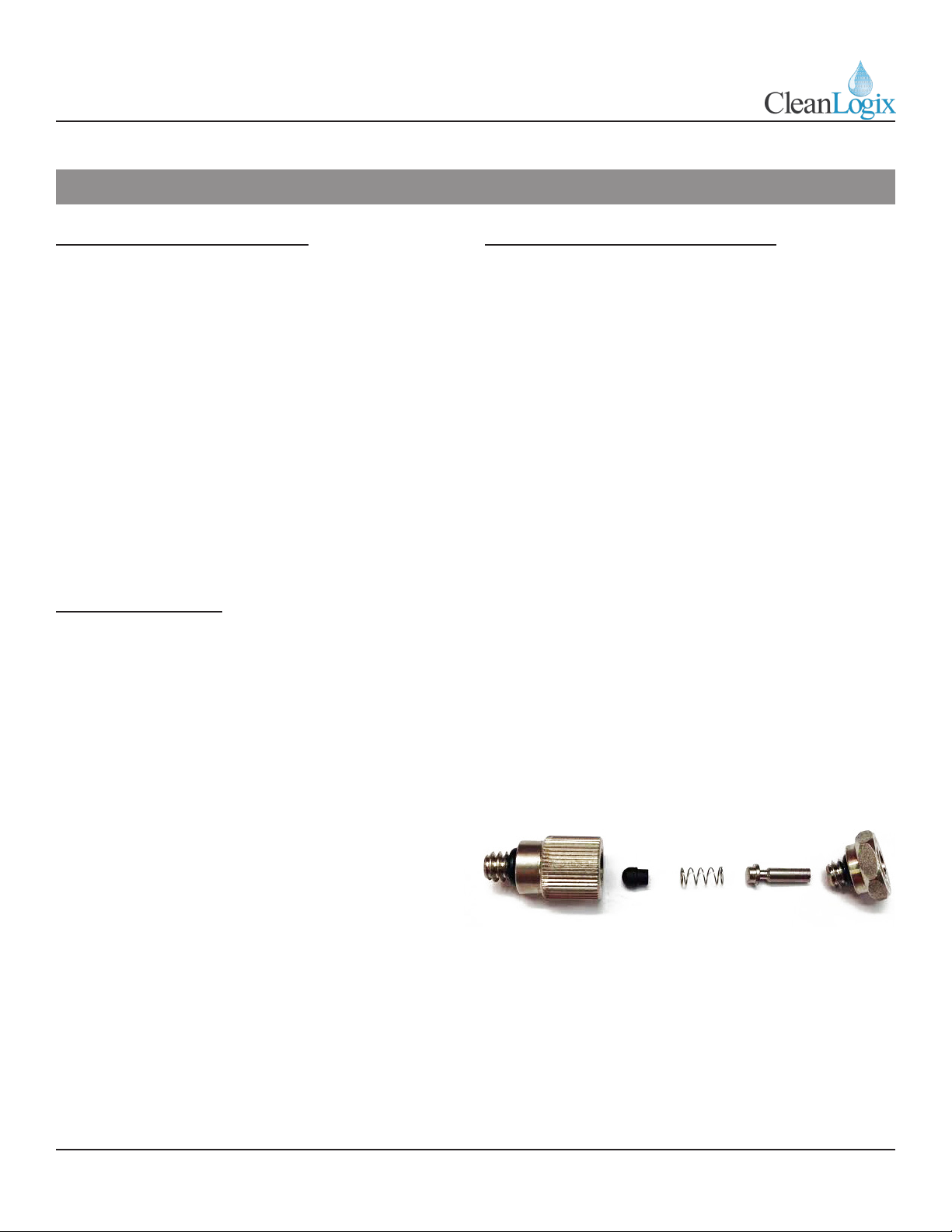
Nozzle Disassembly and Cleaning
1. Unscrew nozzle from outside of trough using
pointer nger and thumb (see parts callout for
more informaon).
2. Remove the rubber shield washer from the nozzle
3. The nozzle can be disassembled by unscrewing
the check valve assembly from the nozzle orice.
• There is a pintle, a rubber bulb and spring
inside the check valve poron of the body.
These parts are VERY small - take cauon not
to lose them! (see below)
4. Clean the body and orice poron of the nozzle
using compressed air and inspect.
5. Re-assemble the nozzle
• Make sure the small rubber p and the pintle
are seated properly inside the spring and are
in the correct orientaon. See image below.
6. Reinstall the shield washer and screw the nozzle
back into the spray bar.
• Finger ghten only! Do NOT use wrenches!
Foot Bath Depth Adjustment
The depth of the foot bath can be adjusted by sliding
the foot bath oat switch assembly up or down.
1. Loosen the screw band clamp which holds the
oat switch.
• Slide oat switch upward to increase the
depth of the bath.
• Slide it downward to decrease the depth.
2. Re-ghten screw band clamp. Do not overghten.
Filter Replacement
The lter should be replaced once per year or
approximately 50,000 acvaons (whichever comes
rst).
1. Turn the switch on the control box to “OFF” to
power down the system.
2. Turn red-handled compressed air relief valve to
“EXH” to exhaust air pressure.
3. Unscrew the blue lter housing and remove lter
4. Install new lter and replace blue housing,
screwing it on hand-ght. Do NOT use a wrench!

FBHS Manual Page 12 of 23 Updated: 05/12/20
USER MANUAL: FBHS-MR
READ ALL INSTRUCTIONS BEFORE OPERATING EQUIPMENT
Troubleshoong
Problem Causes Soluons Notes
The foot bath does not
ll
The drain valve was le
open while the unit was
aempng to ll the
foot bath, causing the
controller to me out
Close the drain valve. If the foot bath or batch
tank fail to ll up within
a specic amount of
me, the unit will stop
aempng to ll them
unl it is reset. This
Prevents excessive water
loss in the event of a
failure.
Reset the unit by turning
the power switch to “OFF”
and then back to “ON”.
The water supply is
turned o or pressure is
excessively low
Make sure the water
supply is ON and the water
pressure regulator on the
unit reads at least 50 psi.
Reset the unit by turning
the power switch to “OFF”
and then back to “ON”.
The foot bath solenoid
valve is faulty or clogged
Reset the unit by turning
the power switch to “OFF”
and then back to “ON”.
Wait for the batch tank
to ll, or manually li the
oat switch inside the
batch tank and then check
to see if the orange light
on the foot bath solenoid
coil connector illuminates.
If the light illuminates but
no water ows, repair or
replace valve.

FBHS Manual Page 13 of 23 Updated: 05/12/20
USER MANUAL: FBHS-MR
READ ALL INSTRUCTIONS BEFORE OPERATING EQUIPMENT
Troubleshoong
Problem Causes Soluons Notes
The foot bath overows The oat switch is faulty
or out of adjustment
Open the drain valve to
lower the water level in
the foot bath such that it is
below the walkway grang.
Reset the unit by turning
the power switch to “OFF”
and then back to “ON”.
Test the oat switch
funcon as detailed in the
maintenance instrucons
and adjust or replace as
necessary.
The hand spray does
not funcon
(See Connued....)
The batch tank is empty
Make sure the water
supply is on and the water
pressure regulator on the
unit reads at least 50 psi.
Reset the unit by turning
the power switch to “OFF”
and then back to “ON”.
Make sure the light on
the batch tank solenoid
coil connector illuminates
and water begins to ow
into the tank. If the light
illuminates but no water
ows, replace the solenoid
valve.
Test the batch tank oat
switch funcon as detailed
in the maintenance
instrucons and adjust or
replace as necessary.
If the foot bath or batch
tank fail to ll up within
a specic amount of
me, the unit will stop
aempng to ll them
unl it is reset. This
prevents excessive water
loss in the event of a
failure.

FBHS Manual Page 14 of 23 Updated: 05/12/20
USER MANUAL: FBHS-MR
READ ALL INSTRUCTIONS BEFORE OPERATING EQUIPMENT
Troubleshoong
Problem Causes Soluons Notes
The hand spray does
not funcon
(connued)
Compressed air supply is
turned o
Make sure the air supply is on
and the red-handled shuto
valve is set to “SUP”. The air
pressure regulator gauge on
the unit should read between
80 and 100 psi.
The hand spray solenoid
valve is faulty or clogged
Check to see if the orange light
on the hand spray solenoid coil
connector illuminates when
the photo eye is tripped. If the
light illuminates but the hand
spray does not acvate, repair
or replace the solenoid valve.
Pump failure
If the hand spray solenoid
valve is open, and compressed
air is supplied to the pump
but it fails to cycle, replace the
pump
Clogged lter
Unscrew the blue lter
housing and check lter or
debris or clogs. Replace the
lter element if necessary.
The batch tank
overows Faulty oat switch
Test the batch tank oat switch
funcon as detailed in the
maintenance instrucons and
replace as necessary.

FBHS Manual Page 15 of 23 Updated: 05/12/20
USER MANUAL: FBHS-MR
READ ALL INSTRUCTIONS BEFORE OPERATING EQUIPMENT
Troubleshoong
Problem Causes Soluons Notes
Poor spray
performance, or some
nozzles spray while
others do not
Clogged nozzles
Turn the power switch to
“OFF” and turn the red-
handled air shuto valve to
“EXH”. Clean or replace the
nozzles as detailed in the
maintenance instrucons. Turn
the power “ON” and the air to
“SUP” and test.
Clogged Filter
Unscrew the blue lter
housing and check lter or
debris or clogs. Replace the
lter element if necessary.
Low air pressure
Make sure the pressure gauge
on the air pressure regulator
reads between 80 and 100 psi.
Please contact your equipment representave
or manufacturer for further support.
iMore Informaon?
FBHS Manual Page 16 of 23 Updated: 05/12/20
USER MANUAL: FBHS-MR
READ ALL INSTRUCTIONS BEFORE OPERATING EQUIPMENT
Appendix A - Parts Callout
DETAIL ON
NEXT PAGE

FBHS Manual Page 17 of 23 Updated: 05/12/20
USER MANUAL: FBHS-MR
READ ALL INSTRUCTIONS BEFORE OPERATING EQUIPMENT
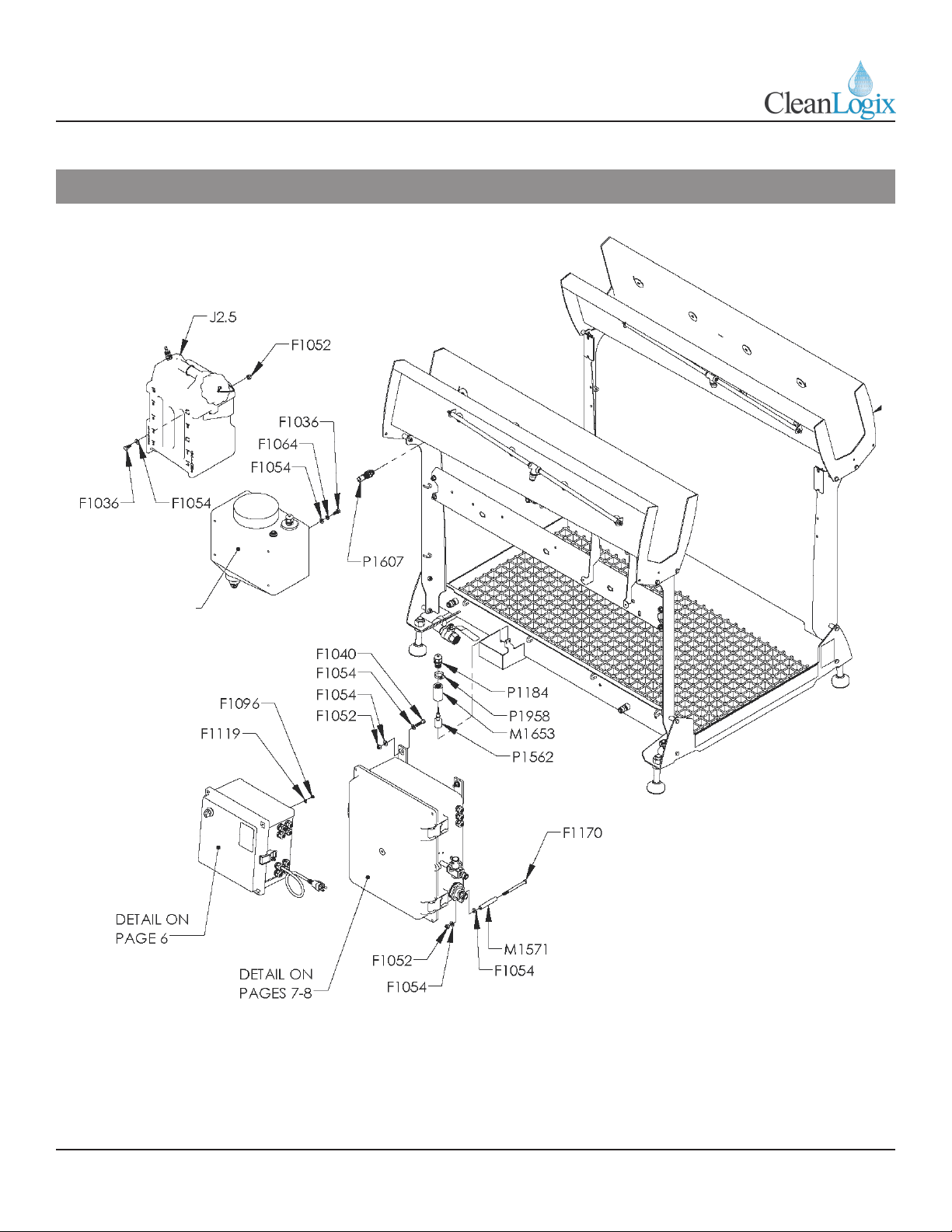
Appendix A - Parts Callout

FBHS Manual Page 18 of 23 Updated: 05/12/20
USER MANUAL: FBHS-MR
READ ALL INSTRUCTIONS BEFORE OPERATING EQUIPMENT
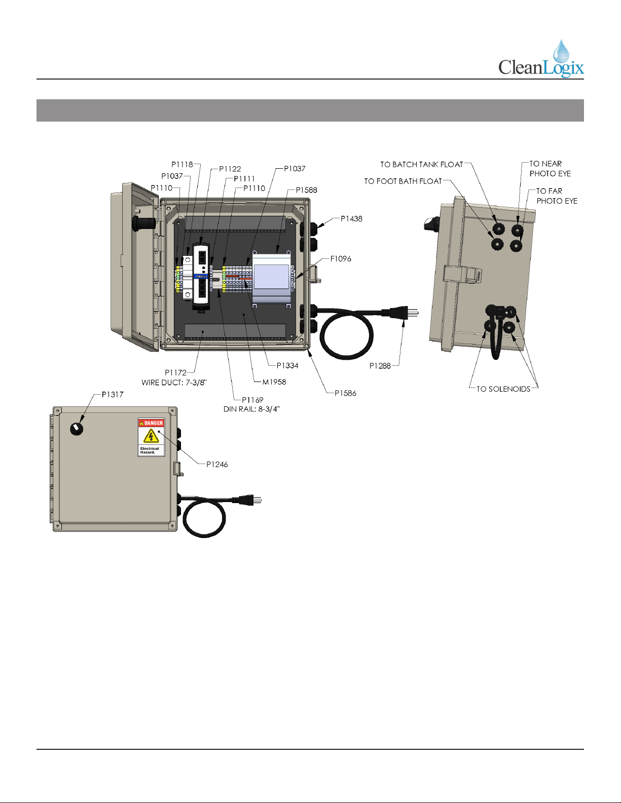
Appendix A - Parts Callout
FBHS Manual Page 19 of 23 Updated: 05/12/20
USER MANUAL: FBHS-MR
READ ALL INSTRUCTIONS BEFORE OPERATING EQUIPMENT
Appendix A - Parts Callout

FBHS Manual Page 20 of 23 Updated: 05/12/20
USER MANUAL: FBHS-MR
READ ALL INSTRUCTIONS BEFORE OPERATING EQUIPMENT
Appendix A - Parts Callout
PART NUMBER DESCRIPTION
F1012 SCREW MACHINE 10-32 x 5/8 SS PHILLIPS
F1024 SCREW MACHINE 1/4-20 x 3/4 SS PHILLIPS
F1036 BOLT HHC 5/16-18 X 3/4 SS
F1039 BOLT HHC 5/16-18 x 1 SS
F1040 BOLT SHCS 5/16-18 X 1-1/4 SS
F1052 NUT NYLOCK 5/16-18 SS
F1054 WASHER 5/16 SS TYPE A
F1064 WASHER SPLIT LOCK 5/16 SS
F1066 NUT NYLOCK 10-32 SS
F1073 SCREW MACHINE 6-32 x 3/4 SS PHILLIPS PAN HD
F1085 WASHER FENDER 5/16 SS
F1096 SCREW MACHINE 10-32 X 3/8 SS PHILLIPS PAN HD
F1096 SCREW MACHINE 10-32 X 3/8 SS PHILLIPS TRUSS HD
F1119 WASHER #10 SS TYPE A
F1125 NUT NYLOCK 6-32 SS
F1128 WASHER SPLIT LOCK 1/4 SS
F1144 NUT HEX 3/4-10 SS
F1169 BOLT HHC 5/16-18 X 1-3/4 SS
F1170 BOLT HHC 5/16-18 X 4 SS
F1179 WASHER SPLIT LOCK #10 SS
M1134 SOLENOID BRACKET
M1557 FBHS HAND TROUGH WELDMENT
M1559 FBHS TUB WELDMENT
M1562 FBHS UPRIGHT WELDMENT RIGHT
M1563 FBHS UPRIGHT WELDMENT LEFT
M1565 FBHS GRATING
M1566 FBHS SPRAY BAR
M1570 STANDOFF 5/16 X 1/2 X 1 SS
M1571 STANDOFF 5/16 X 1/2 X 3 SS
M1652 FBHS BOX MOUNT WELDMENT
M1653 FLOAT SWITCH COUPLER 1/2" X 2" MACHINED
M1658 FBHS PUMP ENCLOSURE PANEL
M1958 "FBHS CONTROLLER BACK PANEL FIBOX AR1010
P1037 TERMINAL BLOCK 2 POS DIN RAIL
P1103 PIPE TEE 1/4 SS
P1110 TERMINAL BLOCK 2 POS GND DIN RAIL
P1111 END STOP TERMINAL BLOCK
P1118 SUPPLEMENTARY PROTECTOR 5A
P1122 POWER SUPPLY 24VDC 60W
P1136 PIPE HEX NIPPLE 1/2 X 1/2 POLY
P1169 DIN RAIL 35mm X 225mm LONG
PART NUMBER DESCRIPTION
P1172 WIRE DUCT 25X60 X 188mm LONG
P1184 CORD GRIP 1/2 NPT X .095-.260 BLK
P1187 SOLENOID CABLE 18mm DIN 24V
P1202 QUICK FIT ELBOW 3/8 NPT X 3/8" TUBE
P1206 GAUGE 1-1/2" DUAL SCALE
P1207 PIPE PLUG 1/8 SQUARE SS
P1209 QUICK FIT ADAPTER 1/4" NPT X 1/4" TUBE
P1211 QUICK FIT 1/4 NPT X 3/8 TUBE
P1213 MOUNTING BRACKET A33-82
P1214 QUICK FIT 3/8" T JOINT POLYPRO
P1219 QUICK FIT 3/8 NPT X 3/8 TUBE
P1221 QUICK FIT ELBOW 1/4" NPT x 3/8" TUBE
P1267 QUICK FIT BULKHEAD 3/8"
P1270 SHUTOFF/LOCKOUT VALVE 1/4 NPT
P1271 3/8" OD POLYETHYLENE TUBING- NATURAL
P1273 QUICK FIT ADAPTER 1/2" NPT x 1/2" TUBE
P1284 EXTERNAL THREADED FEET 3/4" X 4" 1100 LB.
P1288 POWER CORD 18-3 SO 5-15P
P1302 PIPE NIPPLE 1/4 X 3 SS
P1313 REGULATOR 1/4"
P1317 SWITCH, 2-POS SELECTOR, 2NO, BLK
P1334 JUMPER- 4 POSITION
P1345 PIPE BUSHING 1/2" X 1/8" PP
P1359 QUICK FIT ADAPTER 1/2" NPT X 3/8" TUBE
P1367 2.5 GALLON JUG W/ WALL BRKT
P1397 STRAINER Y 1/2" NPT 316SS 100 MICRON
P1398 PRESSURE REGULATOR WATER 1/2" SS
P1399 PRESSURE GAUGE WRG14
P1405 PIPE CLIP 1/2"
P1408 PIPE NIPPLE 1/2 X 2 SS
P1438 CORD GRIP PG9 X .065-.230 BLK
P1450 PIPE BUSHING 3/4" X 1/2" POLY
P1471 MIST NOZZLE .020 SS FULL CONE WITH CHECK
P1472 PIPE ELBOW STREET 3/4 SS
P1475 BALL VALVE 3/4" SS W/ LOCKING LEVER
P1498 BULKHEAD TANK FITTING 1/2" NPT
P1508 1/4" OD POLYETHYLENE TUBING- NATURAL
P1544 QUICK FIT AIR INLET 1/4" FLOWJET P56
P1562 FLOAT SWITCH SPST PVDF 1/8" NPT
P1564 "WIRE, CONTROL CABLE, 20 AWG, 3-CONDUCTOR,
UNSHIELDED, GRAY PVC JACKET"
Other Clean Logix Accessories manuals


