WPI ISO-COP-2 User manual

Instrumenting scientific ideas
WORLD
PRECISION
INSTRUMENTS
ISO-COP-2
Macrosensor for CO Measurement
Serial No._____________________
www.wpiinc.com
INSTRUCTION MANUAL
030316

MACRO SENSORS
SPECIES Carbon
Monoxide Nitric Oxide Hydrogen
Peroxide Oxygen Hydrogen
Sulde
Order Number ISO-COP-2 ISO-NOP ISO-HPO-2 ISO-OXY-2 ISO-H2S-2
Available Diameters 2 mm 2 mm 2 mm 2 mm 2 mm
Response Time < 10 sec < 5 sec < 5 sec < 10 sec < 5 sec
Detection Limit/Range 10nM to 10µM 1 NM to 40µM* < 100nM to
100µM
0.1%-100% < 5nM-100µM
Sensitivity ~0.5 pA/nM ≤ 2 pA/nM 8 pA/µM 0.3-0.6nA/% 2 pA/nM
Drift <1pA/min <1pA/min 0.1pA/min < 1%/min
Temperature Dependent Yes Yes Yes Yes Yes
Physiological Interference nitric oxide NaNO2(10-6 or
better)
None None None
Replacement Sleeves (pkg
of 4)
#95620 #5436 #600012 #5378 #600016
Filling Solution #95611 #7325 #100042 #7326 #100084
Start-up Kit #95699 #5435 #600011 #5377 #600015
*Higher detection limit available on request — call for custom pricing.
• Real-time detection using electrochemical microsensors
• Measure nitric oxide from < 0.3 nM to 100µM.
• Measure hydrogen peroxide < 10 nM to
100mM
• Measure hydrogen sulde
• Measure glucose
• Measure oxygen from 0.1% to 100%
• Integrated system includes one temperature
sensor, your choice of two additional sensors,
and a start-up kit
• Current measurement range from 300 fA to 10
µA (four ranges) permits wide dynamic range
for detection.
• Wide bandwidth allows recording of fast events
• Isolated architecture allows Lab-Trax interface to simultaneously measure free
radical and independent analog data (i.e., ECG, BP, etc.) data on any channel.
Free Radical Analyzer
Other WPI Favorites

ISO-COP-2
World Precision Instruments i
Copyright © 2016 by World Precision Instruments, Inc. All rights reserved. No part of this publication
may be reproduced or translated into any language, in any form, without prior written permission of
World Precision Instruments, Inc.
CONTENTS
ABOUT THIS MANUAL ................................................................................................................... 1
INTRODUCTION .............................................................................................................................. 2
Sensor Design............................................................................................................................ 2
Notes and Warnings................................................................................................................. 2
Parts List...................................................................................................................................... 3
Unpacking................................................................................................................................... 3
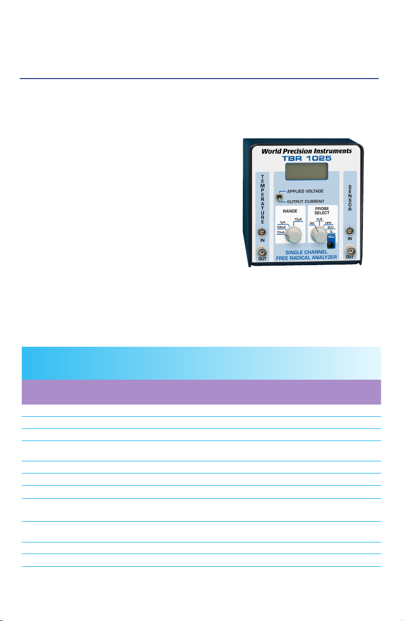
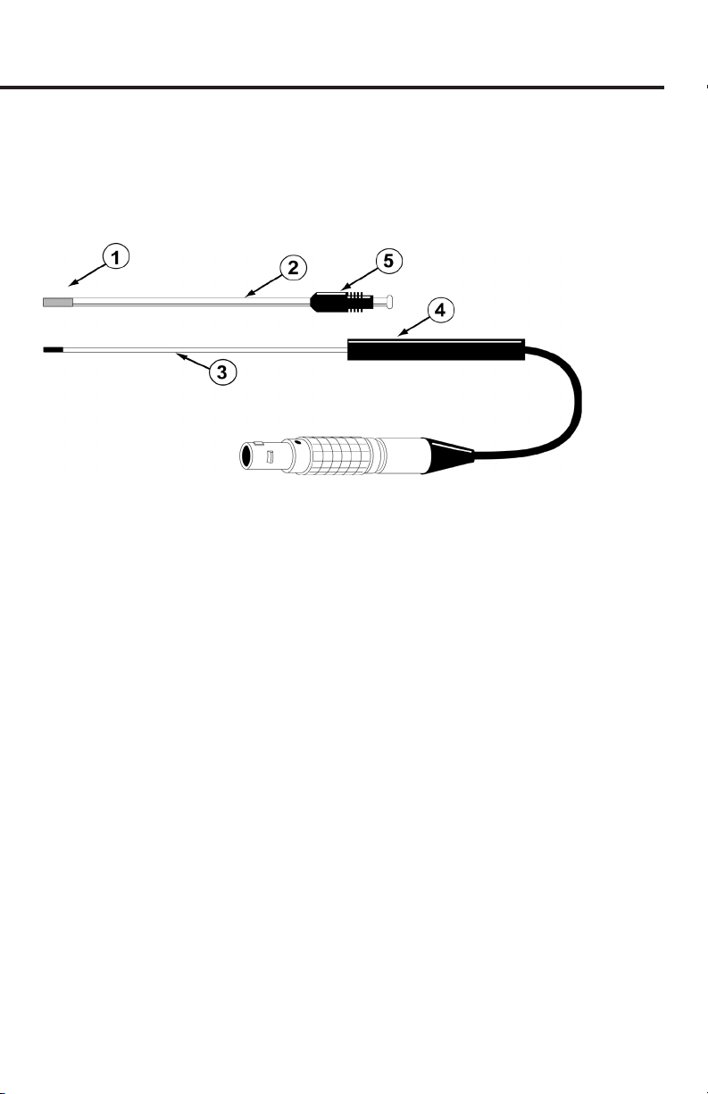
INSTRUMENT DESCRIPTION ........................................................................................................ 5
Structure of the Sensor........................................................................................................... 5
OPERATING INSTRUCTIONS......................................................................................................... 6
Environmental Inuences ....................................................................................................... 6
Temperature......................................................................................................................... 6
Electrical Interference ...................................................................................................... 6
Setup ........................................................................................................................................... 6
Polarizing the Sensor .............................................................................................................. 7
SENSOR CARE AND MAINTENANCE........................................................................................... 8
Durability and Handling........................................................................................................... 8
Storing the Sensor.................................................................................................................... 8
Cleaning the Membrane.......................................................................................................... 8
Sterilizing the Membrane........................................................................................................ 9
Replacing the Membrane Sleeve .......................................................................................... 9
ACCESSORIES.................................................................................................................................11
TROUBLESHOOTING ...................................................................................................................12
SPECIFICATIONS............................................................................................................................13
INDEX...............................................................................................................................................14
WARRANTY .....................................................................................................................................15
Claims and Returns ................................................................................................................15
Repairs.......................................................................................................................................15

ii World Precision Instruments

ISO-COP-2
World Precision Instruments 1
ABOUT THIS MANUAL
The following symbols are used in this guide:
This symbol indicates a CAUTION. Cautions warn against actions that
can cause damage to equipment. Please read these carefully.
This symbol indicates a WARNING. Warnings alert you to actions that
can cause personal injury or pose a physical threat. Please read these
carefully.
NOTES and TIPS contain helpful information.
Fig. 1—ISO-COP-2 sensor

2 World Precision Instruments
INTRODUCTION
The ISO-COP-2 is a carbon monoxide sensor with a replaceable stainless
steel membrane sleeve lled with an electrolyte solution that measures CO in
vivo or in vitro in real time!
Replacement membrane sleeves can be purchased in packages of four (WPI
#95620), along with lling solution (WPI #95611). A startup kit for this sensor
is available and is recommended for the rst purchase of this sensor type
(WPI #95699).
Sensor Design
The ISO-COP-2 is an amperometric sensor designed for use in cell culture
and similar applications.
In principle, CO diuses through the gas-permeable membrane and is then
oxidized to CO2on the working electrode of the sensor. This oxidation
creates a current with a magnitude directly related to the concentration of
CO in solution.
It is designed for use with WPI’s TRB4100 (4-Channel Free Radical Analyzer),
TBR1025 (1-Channel) or the Apollo1000.
Notes and Warnings
WARNING: CARBON MONOXIDE GAS MUST BE HANDLED ONLY IN
A WELL-VENTILATED AREA, TYPICALLY A LABORATORY FUME
HOOD WITH FORCED VENTILATION. THE U.S. OCCUPATIONAL
SAFETY AND HEALTH ADMINISTRATION HAS SET A TIME-
WEIGHTED AVERAGE (8-HOUR) (TWA) PERMISSIBLE EXPOSURE
LIMIT (PEL) OF CARBON MONOXIDE AS 50PPM. THE ACGIH
THRESHOLD LIMIT VALUE (TLV) FOR CARBON MONOXIDE IS 25PPM TWA. THAT
IS TO SAY, 50PPM IS CITED AS THE MAXIMUM CONCENTRATION TO WHICH
WORKERS MAY BE CONTINUALLY EXPOSED. OVEREXPOSURE MAY RESULT IN
HEADACHES, DIZZINESS, CONVULSIONS, LOSS OF CONSCIOUSNESS AND
DEATH. CARBON MONOXIDE IS ALSO EXTREMELY FLAMMABLE. IT IS
THEREFORE CRITICAL THAT THE PERSONNEL HANDLING THE GAS BE
THOROUGHLY FAMILIAR WITH THE MATERIAL SAFETY DATA SHEET (MSDS) AND
PROPER HANDLING PROCEDURES. THE PRECAUTIONS RECOMMENDED BY THE
GAS MANUFACTURER MUST BE FOLLOWED.
CAUTION: DO NOT EXPOSE SENSOR TO ORGANIC SOLVENTS.

ISO-COP-2
World Precision Instruments 3
CAUTION: Carefully read the “Probe Unpacking” instructions (found in the
sealed sensor case) before handling the sensor.
NOTE: The sensor must be polarized for at least 12 hours in 0.1M PBS buer
solution prior to use.
NOTE: The sensor membrane and membrane adhesive are extremely
delicate. Improper handling will lead to damage of the sensor. The ISO-COP-2
is designed for use in liquids.
NOTE: For optimal use of each sensor and sensor membrane sleeve, the
sensor must be stored properly. See “Storing the Sensor” on page 8.
Parts List
After unpacking, verify that there is no visible damage to the sensor. Verify
that all items are included:
(1) ISO-COP-2 CO sensor
(1) Probe Unpacking Instructions (Read this before handling the probe.)
(1) ISO-COP-2 Data sheet
(1) Spare membrane sleeve
(1) 1 cc Syringe
(1) MF28G67 MicroFil
(1) 95611 10mL vial of lling solution
(1) Instruction Manual
Unpacking
Upon receipt of this sensor, make a thorough inspection of the contents and
check for possible damage. Missing cartons or obvious damage to cartons
should be noted on the delivery receipt before signing. Concealed damage
should be reported at once to the carrier and an inspection requested.
Please read the section entitled “Claims and Returns” on page 15 of this
manual. Please contact WPI Customer Service if any parts are missing at
The ISO-COP-2 sensor is shipped in a sealed, rigid plastic, hinged box with
foam padding to avoid damage to your sensor during shipment. The tip of
the sensor is protected by inserting it into a small, plastic vial containing
deionized water (DIW) to keep the membrane from drying out.
To open the package, carefully cut the seals on either side of the sensor box.
Inside the box, on top of the sensor, are the important documents to read

4 World Precision Instruments
before handling the sensor, including the instructions for removal of the
sensor tip from the protection vial. Keep the sensor tip in this vial until the
sensor is ready for use.
KEEP THE SENSOR STORAGE BOX and all the documentation in a safe place.
Use of the sensor should begin within 30 days of receipt.
Returns: Do not return any goods to WPI without obtaining prior approval
(RMA # required) and instructions from WPI’s Returns Department. Goods
returned (unauthorized) by collect freight may be refused. If a return
shipment is necessary, use the original container, if possible. If the original
container is not available, use a suitable substitute that is rigid and of
adequate size. For further details, please read the section entitled “Claims
and Returns” on page 15 of this manual.

ISO-COP-2
World Precision Instruments 5
INSTRUMENT DESCRIPTION
Structure of the Sensor
The basic structure of the ISO-COP-2 sensor is shown below (Fig. 2).
Fig. 2—ISO-COP-2 Sensor assembly
Gas permeable, polymeric membrane covering the end of the stainless
sleeve to separate it from the external environment
Disposable, protective stainless steel sleeve (WPI#95620) that houses the
sensitive electrode pair. The sleeve is anged to properly connect with the
locking cap. It must contain fresh electrolyte (WPI#95611).
Internal CO-sensing pair of working and counter (reference) electrodes
Probe handle
Locking cap attaches the sleeve to the probe handle
When the sensor is fully assembled (with locking cap and sleeve in place)
the internal electrode should press gently against the polymeric membrane,
which will be slightly stretched. This ensures that the electrolyte diusion is as
thin as possible, minimizing sensor response time.
NOTE: Once a membrane is stretched it is permanently deformed and
cannot be reused if the sleeve is removed from the electrode.
Additional membrane sleeves are available in packages of 4 (WPI # 95620).
The ISO-COP-2 start-up kit (WPI #95699) also includes replacement
membrane sleeves, along with all the accessories to ll them properly with
electrolyte solution.

6 World Precision Instruments
OPERATING INSTRUCTIONS
Environmental Inuences
There are two environmental parameters to which CO sensors are quite
sensitive: temperature and electrical interference.
Temperature
The background current (and to a lesser degree) the selectivity of the CO
sensor is aected by temperature. This is due to the eects of temperature
on the partial pressure of dissolved CO gas in liquid samples, on the
permeability of the membrane and on the conductivities of various sensor
components. It is recommended that the calibration procedure be performed
at the same temperature as the experiment and that temperature be held
constant during CO measurement.
Electrical Interference
External, electrical noise sources (like uorescent lights, MRI machines,
electric motors, computers, pumps and other electrical instruments)
may couple into the sensor signal path electromagnetically and impose
undesirable signals in the output record. The magnitude of this external noise
depends on the environment of the laboratory. If the interference introduced
by the electrical signals in the environment is large, the rst step towards
eliminating it is to ground and shield the system properly.
TIP: Refer to your free radical analyzer manual for proper grounding
and shielding techniques. (In the TBR4100 or Apollo1000 manuals, see
“Grounding and Noise Concerns” in the Operating Instructions section.)
Setup
The CO electrolyte lling solution (WPI #95611) must be made fresh when
you are ready to use the sensor, so the ISO-COP-2 sensor is shipped with
a dry membrane sleeve. Before using it, you must ll the sleeve with the CO
electrolyte lling solution. Use the membrane sleeve that was shipped on
your sensor and follow the instructions for replacing a membrane sleeve
(page 9) to setup your sensor for its polarization, calibration and rst use.
NOTE: Since the membrane sleeve that was on the sensor during shipping
was dry, the membrane was not damaged by placing it on the sensor. That
membrane sleeve is still good to use.

ISO-COP-2
World Precision Instruments 7
Polarizing the Sensor
1. Place the sensor in 0.1M PBS solution
2. Plug it into the free radical analyzer.
3. Turn on the free radical analyzer.
4. Set the poise voltage to 950mV.
5. The ISO-COP-2 sensor should be allowed up to 12 hours to reach a stable base-
line current of 1000-8000pA before it is used for measurement.
6. During initial polarization the current is typically very high (well above 10nA), but
within an hour it will begin to decrease rapidly. In order to observe this phenom-
enon, start by setting the range to 100nA. After several hours the current will
fall below 10nA. At that time, adjust the range to 10nA. The 10nA range setting
is required to provide adequate resolution for viewing the sensor’s response to
carbon monoxide.
7. If the stabilized baseline value exceeds 8000pA, see “Replacing the Membrane
Sleeve” on page 9.
NOTE: This polarization procedure assumes the temperature is 25ºC. At 37ºC
the baseline current is higher. If the current exceeds 10nA, it may be required
to adjust the current range up to 100nA.

8 World Precision Instruments
SENSOR CARE AND MAINTENANCE
Durability and Handling
The sensor is relatively durable, except for the membrane sleeve. Exercise
caution when handling any CO sensor to avoid actions that could damage
the sensor tip. Pay particular attention to the sensor membrane, because the
membrane is extremely delicate and improper handling will lead to damage.
Refer to the Probe Unpacking Instructions that came with your sensor for
handling instructions.
CAUTION: Do NOT scratch the sensor membrane sleeve. Do NOT wipe the
sensor membrane with anything, even Kimwipes. If necessary, squirt it with
distilled water or compressed air.
CAUTION: The sensor membrane is easily punctured if it comes into contact
with sharp objects. For example, do NOT let the stir bar come into contact with
the sensor membrane.
Storing the Sensor
With proper care and by following the instructions below a membrane sleeve
should last more than one month.
STANDBY: If the electrode is being used on a daily basis, it should be
left connected to the free radical analyzer in the ON position with the tip
suspended in distilled water.
LONG-TERM: For long-term storage of more than one week, remove the
membrane sleeve, clean the sensor tip with deionized water and dry carefully.
Protect the tip and store the sensor with the membrane removed in a dry,
cool environment.
Cleaning the Membrane
The membrane sleeve itself requires very little maintenance. The primary
concern is to avoid damage to the membrane and to keep it as clean as
possible. After each use the membrane should be cleaned by suspending the
tip in distilled water for 20-30 minutes to dissolve salts and remove particles
which may have accumulated on it. If the probe was used in a protein-rich
solution, the tip should rst be soaked in a protease solution for several
minutes to remove protein build-up, and then in distilled water. Enzymatic
detergent (for example, Enzol, WPI#7363) can also be used.

ISO-COP-2
World Precision Instruments 9
Accumulated organic matter can be removed by briey immersing the tip in a
0.1M HCl or 0.1M NaOH (at times both may be necessary) for 10 seconds.
A good indication of a dirty membrane sleeve is a sluggish response or an
unusually low sensitivity. If these problems are not rectied by cleaning, then
the membrane sleeve should be replaced.
Sterilizing the Membrane
The membrane sleeves can be sterilized chemically using an appropriate
disinfectant (for example, Cidex, WPI#7364).
CAUTION: Do not use alcohol on the sensor.
Replacing the Membrane Sleeve
Even with the best of care and proper maintenance, the membrane sleeve
will eventually need to be replaced.
1. Unscrew the locking cap from the handle.
2. Hold the stainless steel sleeve and remove it and the locking cap from the internal
electrode assembly, being careful not to bend the internal electrode assembly
when doing so.
3. Rinse the internal electrode with distilled water (particularly the tip) and let it soak
for at least 15 minutes. Be careful not to let water get up into the handle.
4. Gently dry the electrode with a soft tissue (Kimwipes). Be sure to dry thoroughly
the at surface at the tip of the electrode. After drying the current should stabilize
fairly quickly to a low value (for example, 0 - 20pA). If this occurs, it is a good indi-
cation that the electrode is functioning properly.
5. If the electrode is not clean, repeat steps 3 and 4.
6. Remove the locking cap from the old used sleeve, and gently slide it onto the new
replacement sleeve. Additional membrane kits (WPI #95620) may be purchased
separately. Filling a single ISO-COP-2 sensor sleeve requires about 1mL.
7. Dip the internal electrode 1-2cm into the ISO-COP-2 electrolyte (WPI #95611 pro-
vided in the ISO-COP-2 start-up kit. The current will rise rapidly oscale. Using the
MicroFil™ nonmetallic syringe needle (WPI #MF28G67-5) and 1mL plastic syringe
(included in the Startup kit) inject approximately 100µL of freshly mixed CO elec-
trolyte lling solution directly into the new sleeve, starting about half way down
the sleeve and drawing the MicroFil out of the sleeve as it lls. The lling process
should be performed slowly enough so as not to create turbulence, which could

10 World Precision Instruments
introduce air bubbles into the electrolyte. The MicroFil (#MF28G67)supplied in
the startup kit is less than the length of the sleeve, so that it will not puncture the
delicate membrane at the tip of the sleeve during injection.
TIP: If air bubbles form in the electrolyte, gently ick or tap the side of the sleeve
to remove the bubbles.
8. Slowly and smoothly insert the electrode into the sleeve, and screw the locking
cap into the handle. The electrode should be observed to press gently against the
membrane (Fig. 3).
Fig. 3—(Right) Membrane placement.
The internal electrode tip should
protrude slightly out into the
membrane.
9. The current displayed on the
meter at this time will be high or
oscale.
10. Suspend the tip of the newly as-
sembled probe in distilled water.
11. After 10-15 minutes the current
should no longer be oscale and
will gradually decrease with time. It may take several (up to 12) hours for the sen-
sor current to reach a low stable value, at which time it will be ready for use.
TIP: The integrity of the new membrane can be determined by immersing the
probe tip into a strong saline solution (1M). If the current increases dramatically
or is oscale then the membrane integrity is not good and a new membrane will
have to be tted. Additional ISO-COP-2 membranes (packages of 4) are available
from WPI (#95620).
The internal electrode tip
should protrude slightly
out into the membrane.

ISO-COP-2
World Precision Instruments 11
ACCESSORIES
Table 1: Accessories
Part Number Description
5399 T-Adapter Kit (pkg. of 3)
95699 ISO-COP-2 Startup Kit*
95620 Replacement Sleeves (pkg. of 4)
95611 ISO-CO Electrolyte Filling Solution (10mL)
7363-4 Enzol - Enzymatic detergent (1 gal.)
MF28G67-5 MicroFil electrolyte lling needle (pkg. of 5)
*The ISO-COP-2 start-up kit (WPI # 95699) contains everything needed to
begin working with this sensor, and the kit is highly recommended for rst-
time ISO-COP-2 users (Fig. 4). The kit includes:
• Five additional membrane sleeves (Future rells are sold in packages of four
sleeves - 95620.)
• 95611–Electrolyte lling solution
• MicroFil™ electrolyte lling needle (Future rells are sold in packages of ve–
MF28G67-5)
• 3563–1mL syringe
• Two sample vials with lids and stoppers
• Potentiometer adjustment tool for use with the TBR4100/1025
1mL syringe
3563
Replacement Sleeves
(
Refills: 95620–pkg of 4)
MicroFill
Needle
MF28G67
Filling
Solution
95611 Vials
Stoppers
POT
Adjustment
Fig. 4—ISO-COP-2 Startup kit

12 World Precision Instruments
TROUBLESHOOTING
Issue Possible Cause Solution
Baseline current is be-
low specied range.
The poise voltage (sensor setting)
may be incorrectly set.
Set the poise voltage to 950mV. Set the
range at 10nA.
The sensor may be nearing the
end of its usable life.
Perform a standard calibration with at
least three points. If the sensor responds
linearly within the desired concentration
range, it is still useable. The calibration
should show that the sensor responds in
a linear fashion.
Unstable base-
line
If the baseline hasn’t stabilized
after 12 hours, the polarizing solu-
tion may be contaminated.
Prepare fresh polarizing solution. Use
0.1M PBS only.
External electrical interferences
may be the problem.
Identify and isolate electrical interfer-
ences.
Calibration data
set is not linear
The dilution factors may be incor-
rect.
Verify the procedure used.
Uneven aliquots may have been
used.
Check the pipetter calibration.
Sensitivity
below range
specied
Membrane is old or worn, or elec-
trolyte solution evaporated.
In either case, Replace the membrane
sleeve. See “Replacing the Membrane
Sleeve” on page 9.
NOTE: If you have a problem/issue with your ISO-COP-2 sensor that falls
outside the denitions of this troubleshooting section, contact the WPI

ISO-COP-2
World Precision Instruments 13
SPECIFICATIONS
The sensor conforms to the following specications:
Outside Diameter 2mm
Response Time < 10 sec
Detection LImit/Range ~10nM
Linear range 10nM–10µM
Nominal Sensitivity (New sensor) ~0.5 pA/nM
Poise Voltage 950mV
Typical Quiescent Baseline Current, 25ºC 3,000pA
Acceptable Baseline Range 1000-8000pA
Polarization Time 12+ hours
Recommended Polarization Solution 0.1M PBS
Temperature Dependent Yes
Physiological Interference NO (nitric oxide)

14 World Precision Instruments
INDEX
Symbols
5399 11
7325 3, 9, 11
7363-4 11
7364 9
A
accessories 11
C
Cidex 9
D
durability 8
E
electrical interference 6
electrode 5
environmental inuences 6
enzymatic detergent 8
F
lling solution 2
G
ground 6
H
handling 8
HCl 9
Hydrogen Peroxide Sensors b
Hydrogen Sulde Sensor b
I
ISO-COP 5, 8, 9
ISO-H2S-2 b
ISO-HPO-2 b
ISO-NOP b
ISO-OXY-2 b
K
Kimwipes 8, 9
L
locking cap 5
M
membrane 5
membrane, cleaning 8
membrane sleeve, replacement 9
MF28G67-5 9, 11
MicroFil 9
N
NaOH 9
Nitric Oxide Sensors b
O
open the package 3
organic solvents 2
Oxygen Sensors b
P
parts list 5
polarize 3
probe handle 5
protease 8
R
replacement membrane 2
returns 4
S
saline solution 10
shield 6
sleeve 5
startup kit 2
sterilize 9
store 3, 8
T
temperature 6

ISO-COP-2
World Precision Instruments 15
* Electrodes, batteries and other consumable parts are warranted for 30 days only from the date on which
the customer receives these items.
WARRANTY
WPI (World Precision Instruments, Inc.) warrants to the original purchaser that this equipment, including
its components and parts, shall be free from defects in material and workmanship for a period of
30 days* from the date of receipt. WPI’s obligation under this warranty shall be limited to repair or
replacement, at WPI’s option, of the equipment or defective components or parts upon receipt thereof
f.o.b. WPI, Sarasota, Florida U.S.A. Return of a repaired instrument shall be f.o.b. Sarasota.
The above warranty is contingent upon normal usage and does not cover products which have been
modied without WPI’s approval or which have been subjected to unusual physical or electrical stress
or on which the original identication marks have been removed or altered. The above warranty will not
apply if adjustment, repair or parts replacement is required because of accident, neglect, misuse, failure
of electric power, air conditioning, humidity control, or causes other than normal and ordinary usage.
To the extent that any of its equipment is furnished by a manufacturer other than WPI, the foregoing
warranty shall be applicable only to the extent of the warranty furnished by such other manufacturer.
This warranty will not apply to appearance terms, such as knobs, handles, dials or the like.
WPI makes no warranty of any kind, express or implied or statutory, including without limitation any
warranties of merchantability and/or tness for a particular purpose. WPI shall not be liable for any
damages, whether direct, indirect, special or consequential arising from a failure of this product to
operate in the manner desired by the user. WPI shall not be liable for any damage to data or property
that may be caused directly or indirectly by use of this product.
Claims and Returns
Inspect all shipments upon receipt. Missing cartons or obvious damage to cartons should be noted on
the delivery receipt before signing. Concealed loss or damage should be reported at once to the carrier
and an inspection requested. All claims for shortage or damage must be made within ten (10) days
after receipt of shipment. Claims for lost shipments must be made within thirty (30) days of receipt of
invoice or other notication of shipment. Please save damaged or pilfered cartons until claim is settled.
In some instances, photographic documentation may be required. Some items are time-sensitive; WPI
assumes no extended warranty or any liability for use beyond the date specied on the container
Do not return any goods to us without obtaining prior approval and instructions from our Returns
Department. Goods returned (unauthorized) by collect freight may be refused. Goods accepted for
restocking will be exchanged or credited to your WPI account. Goods returned which were ordered
by customers in error are subject to a 25% restocking charge. Equipment which was built as a special
order cannot be returned.
Repairs
Contact our Customer Service Department for assistance in the repair of apparatus. Do not return
goods until instructions have been received. Returned items must be securely packed to prevent
further damage in transit. The Customer is responsible for paying shipping expenses, including
adequate insurance on all items returned for repairs. Identication of the item(s) by model number,
name, as well as complete description of the diculties experienced should be written on the repair
purchase order and on a tag attached to the item.

USA
International Trade Center, 175 Sarasota Center Blvd., Sarasota FL 34240-9258
UK
1 Hunting Gate, Hitchin, Hertfordshire SG4 0TJ
Germany
Zossener Str. 55, 10961 Berlin
China & Hong Kong
WPI Shanghai Trading Co., Ltd.
Rm 29a, No8 Dongfang Rd., Pudong District, Shanghai, 200120 PR China
Brazil
Av. Conselheiro Nébias, 756 sala 2611, Santos-CEP: 11045-002, São Paulo Brazil •
Internet
www.wpiinc.com • www.wpi-europe.com • www.wpiinc.cn
Other manuals for ISO-COP-2
1
Table of contents
Other WPI Accessories manuals