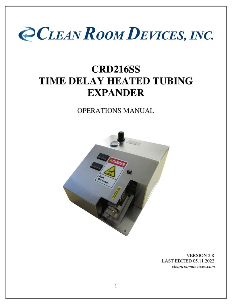
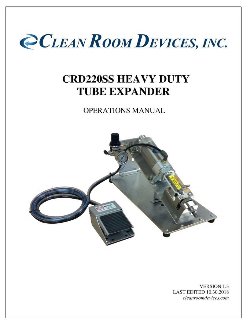
CLEAN ROOM DEVICES CRD200SS User manual

CRD200SS TUBE EXPANDER
OPERATIONS MANUAL
VERSION 4.5
LAST EDITED 09.12.2019
cleanroomdevices.com

1
Table of Contents
Table of Contents…………………….……………………………………………………….....1
1.0 General Product & Safety Information…………………………………………….…....2
1.1 Product Information
1.2 Safety Information
2.0 Installation………………………………………………….………………..….……….3
2.1 Air Supply
3.0 Operation…………………………………………………………………..……...…..…3
3.1 Tube Expanding
3.2 Jaw installation and removal
4.0 Parts List………………………………………………………………………………...7
5.0 Troubleshooting………………………………………….……………….…………..…8
6.0 Maintenance…………………………………………………………………….…….…8
6.1 Periodic Cleaning (annually)
7.0 Safety…………………………………………………………………………………….8
8.0 Product specifications……………………………………………………………………9
9.0 Durometer Scale…………………………………………………………………………9
10.0 Warranty….........................................................................................................................10
10.1 Warranty
10.2 Warranty Period

2
1.0 General Product & Safety Information
1.1 Product Information
The CRD200 SS Tube Expander is designed to expand flexible tubing up to a durometer
of Shore A85 (Shore D35), including any non-metallic braided materials.
The device only works with tubing that has an inside diameter of .040” to 1/2”.
The standard jaw sets are universal and are designed to be used with an inside diameter
range of .040” to 1/2". Other jaw sets are available that are optimized for a specific size
(see accessories page at www.cleanroomdevices.com or call Clean Room Devices, Inc.).
The device features simple yet reliable tool-less jaw adjustment, which can be made by
the operator.
The device features a calibrate-able pressure gage conveniently mounted for additional
process control.
1.2 Safety Information
The device has a foot pedal actuated air cylinder that actuates the expanding jaws. The
unit is not intended to expand anything other than flexible tubing.
Avoid placing your fingers between the upper jaw block and the air cylinder
Mounting bracket while operating unit, sufficient pressure exists to cause personal
injury.
WARNING
GG

3
2.0 Installation
Ensure all five (5) rubber feet are completely stabilized on your work surface prior to applying
air pressure to the unit.
2.1 Air Supply
Connect a 1/4” air supply hose to the inlet on the pressure regulator. The air supply
should be free of moisture and contaminates and provide a minimum of 100 psi (+/- 10%)
The regulator on the unit should be set to 80-120 psi.
3.0 Operation
3.1 Tube Expanding
Using Figure 3.1.1, follow the steps below to achieve proper expanding size.
To adjust the jaws for the size tubing to be expanded you need to loosen the 3/8” hex nut
(Lock Nut).
With the compressed air attached to the expander, actuate the foot pedal which will
activate the expander. Keeping the foot pedal down adjust the expander lower jaw to the
position you want using the Thumb Wheel Knob.
Turning the Thumb Wheel clockwise will increase the jaw expansion size, counter
clockwise will decrease the jaw expansion size. This adjustment may require fine tuning
depending on your tubing I.D., O.D., durometer and/or material.
Once you have the expansion size you want tighten the Lock Nut to secure the
adjustment. Release the foot pedal.
Place the tube over the ends of both expander jaws and hold firmly in place.
Actuate the Tube Expander by pressing the foot pedal.
Once the tube is expanded, release the foot pedal, rotate the tubing 90 degrees on the jaws
and actuate the Tube Expander by pressing the foot pedal again.
Note: Several expanding actions may be necessary to effectively expand the end of
the tube for the fitting/connector to slide in. Each time you expand the tubing
remember to rotate the tubing 90 degrees on the jaws.
Quickly insert the component or tube connector before the tubing regains its original
size.

4
Safety Guard Jaw Set
Thumb Wheel Lock Nut
Figure 3.1.1
3.2 Jaw installation and removal
Tools required are 9/16 open wrench, 11/16 open wrench, 3mm, 4mm and 3/32nd hex
wrench
Remove jaw guard by removing two 5x10mm screws using a 3mm hex wrench.
Turn the thumb wheel clockwise until the cylinder shaft is fully extended in the jaw block
channel to remove force from the cylinder. Figure 3.2.1
Cylinder shaft shown fully extended in jaw block channel
Figure 3.2.1

5
Using a 11/16 open end wrench break the upper jaw nut loose by turning counter
clockwise. Figure 3.2.2
Using a 9/16 open end wrench break the lower jaw nut loose by turning clockwise.
Figure 3.2.3
Figure 3.2.2 Figure 3.2.3
Now remove the two 5x12mm screws holding the front cylinder mount bracket using a
4mm hew wrench. Figure 3.2.4. Flip the cylinder backwards until it stops. Figure 3.2.5
Remove two 5x12mm screws
Figure 3.2.4 Figure 3.2.5
Rotate the upper jaw by hand turning counter clockwise until removed.
Important note: when screwing upper jaw onto cylinder shaft it is important to only
screw the jaw 1/2 to 2/3 of the way on. Any farther and the jaw may slip off the jaw
block when the cylinder is retracted.

6
Remove the Knurled lock nut and grab threaded rod by hand and rotate threaded rod
counter clockwise while holding the lower expander jaw until the jaw is removed. Figure
3.2.6
Rotate rod while holding lower jaw
Figure 3.2.6
Select replacement jaw set and assemble them in the reverse order of previous operations.
Note: If the UP/DOWN alignment of the jaws are incorrect the cylinder shaft will
either not retract, or may slow down or stop when extending. The adjustment of
both set screws on the front cylinder mount bracket will need to be adjusted. To
make the adjustment you must first loosen the two 5x12mm screws using a 4mm hex
wrench (Figure 3.2.6) and then by adjusting the two set screws using a 3/32nd hex
wrench. Figure 3.2.7. Now tighten the two 5x12mm screws and assure jaw
alignment.
5x12 mm screws Set Screw (One per side)
Figure 3.2.6 Figure 3.2.7

7
4.0 Parts List
Item
Part Number
Description
1
CD002-002
Base Assembly
2
P00026
Rubber Foot
3
P00057
Threaded Rod
4
P00059
3/8-16 Hex Nut
5
P00056
Steel Flat Washer
6
P00086
Nylon Flat Washer
7
CD002-137
Thumb Knob
8
P00059
3/8-16 Hex Nut
9
CD002-138
Lower Jaw Block
10
P00058
7/16-20 Hex Nut
11
CD002-055
Jaw Guard
12
P00085
3/4-16 Hex Nut
13
CD002-116
Front Cylinder Mounting Bracket
14
P00141
Flow Valve
15
P00022
Muffler
16
P00027
Rear Cylinder Mounting Bracket
17
P00063
90° Elbow Air Fitting
18
P00066
Regulator
19
P00067
Regulator Nut
20
P00280
Pressure Gauge
21
CD001-0027
Nameplate

8
5.0 Troubleshooting
Operating Error
Action
Unit does not operate.
1. Check the facility air.
2. Check all air hose connections on the unit.
Jaws do not expand.
1. Ensure there are no obstructions keeping the
jaws from expanding.
2. Completely depress the foot pedal to actuate.
3. Verify that the tubing is within the
recommended durometer and size range.
Flexible tubing is splitting/tearing.
1. Verify that the tubing is within the
recommended durometer and size range
2. Ensure the lower jaw has been adjusted
correctly for the tubing inside diameter (I.D.).
3. Verify facility air supply psi or unit pressure
adjustment.
6.0 Maintenance
6.1 Periodic Cleaning (annually)
Wipe down outer surfaces with alcohol, septihol or mild detergents as required.
7.0 Safety
The jaws are a PINCH POINT, therefore DO NOT OPERATE the Tube Expander
without the clear safety guard bolted in place.

9
8.0 Product Specifications
Unit Weight
12.0 LBS / 5.44 KG
Overall Dimensions
14.5”l x 7.0”w x 7.0”h
Minimum Facility Air Supply
100 PSI (+/- 10%)
Unit Air Regulator Setting
80-120 PSI
9.0 Durometer Scale

10
10.0 Warranty
10.1 Warranty
The manufacturer warrants the product manufactured by it, when properly installed, operated, applied and
maintained in accordance with the procedures and recommendations outlined in the manufacturer’s operation
manual, to be free from defects in material or workmanship for a period as specified below, provided such defect
is discovered and brought to the manufacturer’s attention within the stated warranty period.
The manufacturer will repair or replace any product or part determined to be defective by the manufacturer within
the warranty period, provided such defect occurred in the normal service and not as a result of misuse, abuse,
neglect or accident. Normal maintenance items requiring routine replacement are not warranted. The warranty
covers parts and labor for the warranty period unless otherwise specified. Repair or replacement shall be made at
the factory or the installation site, at the sole discretion of the manufacturer. Any service performed on the product
by anyone other than the manufacturer must first be authorized by the manufacturer.
Unauthorized service voids the warranty and any resulting charge or subsequent claim will not be paid. Products
repaired or replaced under warranty shall be warranted for the unexpired portion of the warranty applying to the
original product.
The foregoing is the exclusive remedy of any buyer of the manufacturer’s product. The maximum damages
liability for the manufacturer is the original purchase price of the product or part.
THE FOREGOING WARRANTY IS EXCLUSIVE AND IN LIEU OF ALL OTHER WARRANTIES,
WHETHER WRITTEN, ORAL, OR STATUTORY, AND IS EXPRESSLY IN LIEU OF THE IMPLIED
WARRANTY OF MERCHANTABILITY AND THE IMPLIED WARRANTY OF FITNESS FOR A
PARTICULAR PURPOSE. THE MANUFACTURER SHALL NOT BE LIABLE FOR LOSS OR DAMAGE BY
REASON OF STRICT LIABILITY IN TORT OR ITS NEGLIGENCE IN WHATEVER MANNER
INCLUDING DESIGN, MANUFACTURE OR INSPECTION OR THE EQUIPMENT OR ITS FAILURE TO
DISCOVER, REPORT, REPAIR, OR MODIFY LATENT DEFECTS INHERENT THEREIN.
THE MANUFACTURER, HIS REPRESENTATIVE OR DISTRIBUTOR SHALL NOT BE LIABLE FOR
LOSS OF USE OF THE PRODUCT OR OTHER INCIDENTAL OR CONSEQUENTIAL COSTS, EXPENSES,
OR DAMAGES INCURRED BY THE BUYER, WHETHER ARISING FROM BREACH OF WARRANTY,
NEGLIGENCE OR STRICT LIABILITY IN TORT.
The manufacturer does not warrant any product, part, material, component, or accessory manufactured by others
and sold or supplied in connection with the sale of manufacturer’s products.
10.2 Warranty Period
Parts and labor are for ninety (90) days from the date of shipment from the factory. Freight to the factory on units
that the manufacturer requests to be returned shall be paid by the purchaser, all return freight to be paid by the
manufacturer; means of transportation to be specified by the manufacturer.
For additional information contact: www.cleanroomdevices.com
Clean Room Devices, Inc.
10855 Dover Street, Suite 100
Westminster, CO 80021
303-438-0853
Table of contents
Other CLEAN ROOM DEVICES Extender manuals
Popular Extender manuals by other brands

Cisco
Cisco 2332TQ Hardware installation guide

PROception
PROception proSAT1EYE quick start guide

Marantz
Marantz RX9001 Specifications

Rose electronics
Rose electronics CrystalLink USB3.1 Fiber Dual Port Installation

Gefen
Gefen EXT-CAT5-5600A user manual

weBoost
weBoost Drive 3G-X SmarTech III 470011 installation instructions