CLEAN ROOM DEVICES CRD216SS User manual

1
CRD216SS
TIME DELAY HEATED TUBING
EXPANDER
OPERATIONS MANUAL
VERSION 2.7
LAST EDITED 01.07.2021
cleanroomdevices.com

2
Table of Contents
Table of Contents…………………….…………………………………………………………...2
1.0 General Product & Safety Information…………………………………………….…..…3
1.1 Product Information
1.2 Safety Information
2.0 Installation………………………………………………….………………..….………..4
2.1 Air Supply
2.2 A/C Power
2.3 Connection Setup
3.0 Operation…………………………………………………………………..……...…..….5
3.1 Tube Expanding
3.2 Jaw Installation and Removal
3.3 Setting the Time Delays
4.0 Maintenance…………………………………………………………………….…….…14
4.1 Verifying temperature
4.2 Periodic Cleaning (annually)
4.3 Heater Calibration (Delta Controls)
5.0 Troubleshooting………………………………………………………………………....18
6.0 Product Specifications………………………………………………………………..…19
7.0 Durometer Scale………………………………………………………………………...19
8.0 Electrical Diagram…………………...……………………………………………….....19
9.0 Parts List…………………………………..…………………………….………..….….20
10.0 Warranty……………………………………………………………………………… 22
10.1 Warranty
10.2 Warranty Period

3
1.0 General Product & Safety Information
1.1 Product Information
The CRD216SS is designed to expand stiffer tubing such as nylon, polyethylene,
polypropylene and Teflon tubing. With the heater off, the unit can also expand flexible
tubing up to a durometer of Shore A 85 (Shore D 35), including any non-metallic braided
materials
The minimum/maximum inside tube diameter is .040” –1/2”
The unit operates up to a temperature of 350 °F
The standard jaw sets are universal and are designed to be used with an inside diameter
range of .040” to 1/2". Other jaw sets are available that are optimized for a specific size
(see accessories page at www.cleanroomdevices.com or call Clean Room Devices, Inc.).
The unit design allows for simple operator adjustment
1.2 Safety Information
This product uses an air cylinder and foot pedal to pneumatically actuate and expand the
jaws. The unit is not intended to expand anything other than flexible tubing.
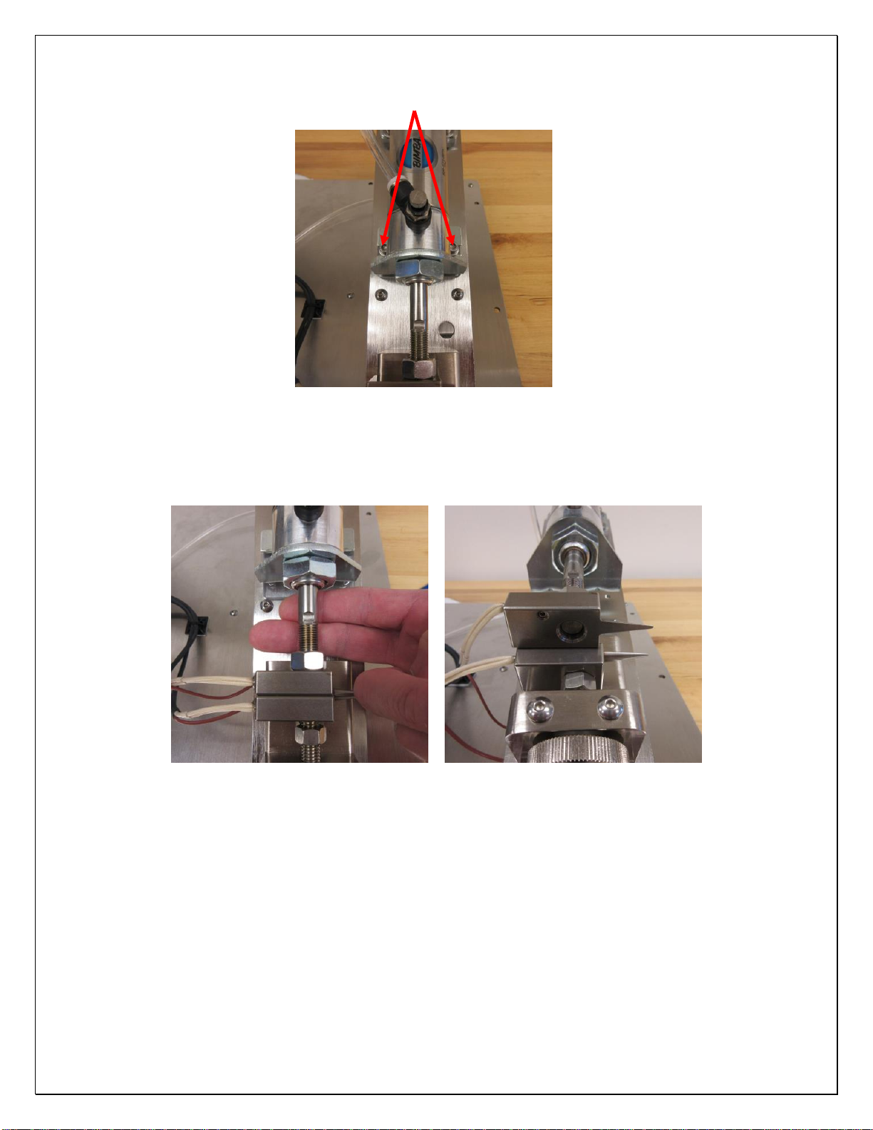
Avoid placing your fingers between the upper jaw block and the air cylinder
mounting bracket while operating unit, sufficient pressure exists to cause personal
injury.
After heating up, the metallic areas in and around the jaws will be extremely hot.
Avoid direct contact with the jaw set while the heater is on. Surface will be hot
enough to cause severe burns.
WARNING
WARNING

4
2.0 Installation
Ensure all five (5) rubber feet are completely stabilized on your work surface prior to applying
air pressure to the unit.
2.1 Air Supply
Connect a 1/4” air supply hose to the inlet on the pressure regulator. The air supply
should be free of moisture and contaminates and provide a minimum of 100 psi.
The regulator on the unit should be set to 80-120 psi.
2.2 A/C and DC Power
This product uses standard 60Hz alternating current power provided by your local utility.
Ensure that you use the correct power supply (120VAC/24VDC) for the type of power in
your region. The heaters and digital controllers are powered by the 120VAC power
source, and the time-delay circuitry is powered by the 24VDC power source. Both must
be present to operate.
2.3 Connection Setup
Connections on the CRD216SS are simple. Refer to Figure 2.3.1 below when making all
connections to the back panel.
Toggle Switch
Power Jack
Foot Pedal Hookup
On
Off
Jaw Hold-Open
Toggle Switch
On
Off

5
Figure 2.3.1
3.0 Operation
3.1 Tube Expanding
Jaw Set
Thumb Wheel Locking Hex Nut
CAUTION: THE UNIT CAN BECOME EXTREMELY HOT. CARE MUST BE USED
AT ALL TIMES WHEN EXPENDING AND DURING JAW INSTALLATION AND
REMOVAL.
To adjust the jaws for the size tubing to be expanded you need to first loosen the
Locking Hex Nut.
With A/C power and compressed air attached to the expander, depress the electric foot
switch to activate the expander. Adjust the expander lower jaw to the position you want
using the Thumb Wheel Knob.
Turning the Thumb Wheel clockwise will increase the jaw expansion size, counter
clockwise will decrease the jaw expansion size. This adjustment may require fine tuning
depending on your tubing I.D., O.D., durometer and/or material.
Once you have the expansion size you want tighten the Locking Hex Nut to secure the
adjustment. Release the foot pedal.
Place the tube over the ends of both expander jaws and hold firmly in place.
Actuate the Tube Expander by pressing the foot pedal.

6
Once the tube is expanded, release the foot pedal, rotate the tubing 90 degrees on the jaws
and actuate the Tube Expander by pressing the foot pedal again.
Note: Several expanding actions may be necessary to effectively expand the end of
the tube for the fitting/connector to slide in. Each time you expand the tubing
remember to rotate the tubing 90 degrees on the jaws.
Once the tube is expanded satisfactorily, release the foot pedal and immediately complete
any secondary assembly application before the tubing regains its original size.
3.1.A Using the Jaw Hold-Open Feature
A Jaw Hold-Open switch has been installed on the tubing expander. This makes setting
the gap between the jaws much simpler.
1) With the toggle switch in the “ON” position, flip the jaw hold-open switch to the
“ON” position (UP).
2) Use the foot pedal to trigger the cycle. The upper jaw will retract and remain open.
3) Flip the jaw hold-open switch to “OFF” position (DOWN) and the upper jaw will
return to the non-expanded position.

7
3.2 Jaw Installation and Removal
CAUTION: THE UNIT CAN BECOME EXTREMELY HOT. CARE MUST BE USED
AT ALL TIMES WHEN EXPENDING AND DURING JAW INSTALLATION AND
REMOVAL.
Tools required are 3/8”, 9/16”and 11/16”open ended wrenches, 2mm, 2.5mm, 3mm,
4mm and 3/32nds hex wrenches.
Remove the two 4x8mm screws attaching the Thermocouples to the upper and lower jaw
using a 2.5mm hex wrench. Figure 3.2.1 and 3.2.2 Note: Be sure to label each
thermocouple and/or heater cartridge as to its position, upper or lower, and be sure to
replace them in the correct positions. The unit will not operate correctly otherwise.
Figure 3.2.1 Figure 3.2.2
Turn the thumb wheel clockwise until the cylinder shaft is fully extended in the jaw block
channel to remove force from cylinder shaft. Figure 3.2.3
Cylinder shaft shown fully extended in jaw block channel

8
Figure 3.2.3
Using a 3/8” open end wrench to hold the flats on the cylinder shaft and an 11/16”open
end wrench on the hex nut, break the upper jaw nut loose by turning it counter clockwise.
Figure 3.2.4
Using a 9/16 open end wrench break the lower jaw nut loose by turning it clockwise.
Figure 3.2.5
Figure 3.2.4 Figure 3.2.5
Now remove the two 5x20mm screws holding the front cylinder mount bracket using a
4mm hex wrench. Figure 3.2.6.

9
Remove two 5x20mm screws
Figure 3.2.6
Place two fingers under the cylinder shaft and lift until the upper jaw clears the lower
jaw. Figure 3.2.7 and 3.2.8
Figure 3.2.7 Figure 3.2.8
Use a 2mm hex wrench to loosen the set screws in each jaw and then remove the heating
element probes. Figure 3.2.9 and 3.2.10

10
Figure 3.2.9 Figure 3.2.10
Flip the cylinder backwards until it stops. Figure 3.2.11
Figure 3.2.11
Rotate the upper jaw by hand turning it counter clockwise until the jaw can be removed.
Important note: when screwing upper jaw onto cylinder shaft it is important to only
screw the jaw 1/2 to 2/3 of the way on. Any farther and the jaw may slip off the jaw
block when the cylinder is retracted.
Loosen the locking hex nut and grab threaded rod by hand and rotate threaded rod
counter clockwise while holding the lower expander jaw until the jaw is removed. Figure
3.2.12
Rotate rod while holding lower jaw

11
Figure 3.2.12
Select replacement jaw set and assemble them in the reverse order of previous operations.
Be sure to replace the thermocouples and heater cartridges in the correct positions. The
unit will not operate correctly otherwise.
Note: If the UP/DOWN alignment of the jaws are incorrect the cylinder shaft won’t
retract when trying to be cycled. The adjustment of both set screws on the front
cylinder mount bracket will need to be adjusted. To make the adjustment you must
first loosen the two 5x20mm screws using a 4mm hex wrench (Figure 3.2.13) and
then by adjusting the two set screws using a 3/32nd hex wrench. Figure 3.2.14. Now
tighten the two 5x20mm screws and assure jaw alignment.
5x20mm screws Set Screw (One per side)
Figure 3.2.13 Figure 3.2.14
3.3 Setting the Time Delays

12
The CRD216SS expansion operation is designed to let the operator expand each piece of
tubing twice. After the first expansion, the jaws will close and the operator rotates the
tube 90 degrees and the jaws will automatically expand again using the sensor. This
ensures that the tubing is expanded in a uniform fashion, and not deformed in only one
direction. To assist with this 2-step expansion operation, there are 2 time delay relays on
the unit.
oExpansion Time –This setting adjusts the rate (0.5-5.0 seconds) at which the
tube expansion occurs. The rate at which the tube is expanded is critical to
prevent tearing. Some stiffer tubing might need a longer expansion time, while
softer tubing can be expanded rapidly.
oInterval Time –This setting adjusts the time delay rate (0.5-5.0 seconds) at
which the jaws will cycle. It is adjusted to allow the operator to rotate the tubing
90 degrees at a comfortable pace between expanding.
Remove the hole plugs with a screwdriver on the rear cover to gain access to the Time
Delay adjustment pots. Figure 3.3.1
Figure 3.3.1
Using a small Phillips drive screwdriver adjust the Time Delay relays. Figure 3.3.2

13
Figure 3.3.2
Figure 3.3.3 below shows the CRD216SS with the rear cover removed, as well as the
location of both time delay adjustments on the time delay relay:
Figure 3.3.3
Interval Time
Adjustment
Expansion Time
Adjustment

14
4.0 Maintenance
4.1 Verifying Temperature
To verify the operational temperature, place a ring terminal measuring probe between the
thermocouple and the upper jaw, as shown below:
Spade-head probe and connector
Probe placed between thermocouple & jaw
4.2 Periodic Cleaning (annually)
Wipe down outer surfaces with alcohol, septihol or mild detergents as required.
Ensure the control box does not have a significant amount of dust or debris buildup
within it.
4.3 Heater calibration for Delta DTB Controller
Adjusting the temperature on the Delta controls is a simple task.
Using the “UP” and “DOWN” arrows, adjust the temperature to the desired setting and
press the “SET” button to store your settings. Figure 4.3.1

15
Press to store desired temperature Lower Temperature Raise Temperature
Figure 4.3.1

16
4.4 Delta DTB Controller User Guide
At power-up Temperature Controller displays "no Cont"
* No thermocouple connected to controller *
** Thermocouple is polarity sensitive **
Press "Set" key for more than 3 seconds to enter Initial Setting Mode
Press “up” & “down” key to change inPt to the thermocouple type connected to Temperature Controller
Press "Set" key to accept the set value of the parameter (The controller will automatically return to
the main operating mode when the thermocouple type is set)
Note: J1 and J2 type sensors in OTA controller have been combined to form J type sensor in the OTB.
The upper limilt of J type sensor
=
1200oC. With SP (decimal point) set to 1, the upper limit is limited to 999.9°C
The below procedure is written with CntL mode set to on/oFF mode (most commonly used mode)
Press "Set" key for more than 3 seconds to enter Initial Settings Mode
Press the “scroll” key to scroll thru the parameters
Press the “up” and “down”
key to change the parameter, the parameter will flash while changes are being made
Press the "Set" key to accept the set value of the parameter
Initial Setting Mode
Parameter
Explanation
Set Values
tPun
Temperature Unit - ° C/o F
F
tp-H
Temperature Probe High Limit (auto set to thermocouple type set
XXX)(
in "inPt", see section 5 in manual)
tP-L
Temperature Probe Low Limit (auto set to thermocouple type set
XXXX
in "inPt", see section 5 in manual)
CtrL
Control Mode (Pro 6, manu, onof and Pid)
Pid
S-HC
Select Heating / Cooling control (see section 7 in manual)
Heat
example: HIC2 - Heat
=
output 1, Cool
=
output 2
ALA1
Alarm 1 type (see section 8 in manual)
0
ALA2
Alarm 2 type (see section 8 in manual)
0
* ALA3 is inactive in Dual Loop Mode*
* In Operation Mode, alarm limits change according to alarm types
set in ALA 1 and ALA2.
example: Set S-HC to H 1 C2 (Heat
=
output 1 / Cool
=
output 2)
Set ALA 1 to alarm type 2 (deviation upper-limit)
Set ALA2 to alarm type 3 (deviation lower-limit)
Alarm limits will be displa~ed as follows:
AL 1H
AL2L
SALA
System Alarm - can be set to ALA 1 - ALA3 output
OFF
example: Alarm 1 mode set to high limit and System Alarm set to
Alarm 1. Alarm 1 will activate when PV is greater then SV + AL 1 H
OR when System Alarm matches any of the following conditions
1 - Broken sensor connection
2 - Sensor input error
3 - Heating, temperature goes low for two minutes OR cooling,

17
temperature goes high for two minutes
CoSH
Communication Write Function
OFF
C-SL
Communication Format
ASCII
C-no
Communication Address
3
BPS
Communication Baud Rate
38y4
LEN
Data Length
7
Prty
Parity
None
Stop
Stop Bit
2
Press "SET" key for less than 3 seconds to enter Regulation Mode
Regulation Mode
Parameter
Explanation
Set Values
HtS
Heating Hystereisis (SV - HtS
=
output X ON)
0
example: CtrL
=
H1C2, SV
=
70° F, HtS
=
5 - when PV reaches
65° F output 1
=
ON
CtS
Cooling Hystereisis (SV + CtS
=
output X ON)
0
example: CtrL
=
H1C2, SV
=
70° F, CtS
=
5 - when PV reaches
75° F output 2
=
ON
Dead
Dead Band (see section 7)
0
tPoF
Temperature Probe offset - Regulate temperature deviation value
0
of thermocouple
CrHi
Regulate upper-limit of analog value
0
CrLo
Regulate lower-limit of analog value
0
Press key to enter Operation Mode
Operation Mode
Parameter
Explanation
Set Values
r-S
Controll Setting - Run / Stop
Run
SP
Decimal set point selection (exept for thermocouple type B, Sand R)
0
AL1H
Upper-limit Alarm 1 (only available when ALA1 is enabled)
0
AL2H
Upper-limit Alarm 2 (only available when ALA2 is enabled)
0
AL 1L
Lower-limit Alarm 1 (only available when ALA 1 is enabled)
0
AL2L
Lower-limit Alarm 2 (only available when ALA2 is enabled)
0
*See Alarm Output Operation in section 7
**
PV must go ABOVE or BELOW SV for ALM output
=
on
example: SV
=
70° F, AL 1 H
=
10 - when PV reaches 81° F AL
=
on
SV
=
70° F, AL 2L
=
10 - when PV reaches 59° F AL
=
on
LoC
Lock setting mode (see section 7 in manual)
oFF
LoC 1 will lock out ALL settings
LoC 2 will lock out all settings except SV

18
Notes:
1 - To reset controller to factory default settings: Place controller into
LoC 1 mode, press the ~
!':I
keys simultaneously for more then
3 seconds, press the ~ key to display PASS, change number
to 1357, press SET, cycle power to the controller
2 - To release lock, press SET and ~keys Simultaneously
To set the controller to “Auto Tune” Mode:
1. Press the “Set” key and release. The unit should display “AT off”.
2. Press the UP arrow key so the unit flashes “ON”.
3. Press the “Set” key again. The unit will display “AT on.” If the “Set” key is pressed
again, the unit will return to the normal temperature/set display screen.
4. The unit will Auto Tune the controllers. The heat level go up and down, until the until
calibrates and stabilizes. The procedure will take about 10-15 minutes.
5.0 Troubleshooting
Operating Error
Action
Unit does not operate.
1. Check the facility air connection.
2. Check all air hose connections on the unit.
Flexible tubing is splitting/tearing.
1. Ensure the tubing being expanded does not
exceed the recommended durometer.
2. Ensure the lower jaw has been adjusted
correctly for the tubing inside diameter (I.D.).
3. Verify facility air supply psi or unit pressure
adjustment.
Heaters are not operational or are operating at too
low/high a temperature
1. Check the connectivity of the thermocouples
and heating elements.
2. Verify that the control unit has power.
3. Calibrate the heater controllers (see previous
pages)

19
6.0 Product Specifications
Unit Weight
21 LBS / 9.5 KG
Overall Dimensions
14.5 in. lg. x 12 in. w. x 9 in. ht.
Minimum Facility Air Supply
100 PSI
Unit Air Regulator Setting
80-120 PSI
7.0 Durometer Scale
8.0 Electrical Diagrams

20
9.0 Parts List
Item No.
Part No.
Description
1
216-001
Base
2
216-004
Cover
3
P00088
TEMPERATURE CONTROLLER
4
P00490
FAN, COOLING, 3.15 SQ X 1.00 DP, MCM 1976K910
5
P00111
PRESSURE GAUGE, PANEL MOUNT, 0-160 PSI
6
P00063
FITTING, AIR, 90 DEG. ELBOW, 1/4 TUBE, 1/8NPT
7
P00066
REGULATOR, AIR, 1/8 NPT
8
P00067
NUT, REGULATOR, PANEL MOUNT
9
P00094
CORD GRIP, LIQUID-TIGHT, NYLON
10
P00092
POWER ENTRY MODULE
11
CD202-008
MODIFIED COVER, ELECTRONICS Part#J-6850AR1*01
12
P00264
RELAY, TIME DELAY
13
P00265
RELAY, PANEL MOUNT, SPNO 25A 24VDC
14
P00094
CORD GRIP, LIQUID-TIGHT, NYLON
15
P00108
SOLENOID VALVE, 3 WAY
16
P00026
RUBBER FOOT - MCMASTER PN 9540K56
17
P00057
THREADED ROD, .375-16 X 4, 18-8 SS
18
P00059
HEX NUT, .375-16, 18-8 SS
Other manuals for CRD216SS
1
Table of contents
Other CLEAN ROOM DEVICES Extender manuals