Clean Water J-PRO-22 Installation manual


Rev-042123
J-PRO-22 Proportional Citric Acid Installation Guide
Thank you for purchasing a Clean Water System!
Please review this start-up guide entirely before beginning to install your system and follow the
steps outlined for best results.
Specications:
Pumps 0.1 to 22 gallons of solution per day
Injects into line pressures up to 110 PSI
Dual voltage. 110V or 220V, works on either voltage.
Uses maximum 22 watts of power.
Dimensions:
5-gallon model: 10” x 10” x 15”. Height including pump is 26”
15-gallon model: 14.5” wide x 24”, height including pump is 35”.
35-gallon model: 18” wide x 33”, height including pump is 44”.
CITRIC ACID CAN DAMAGE CLOTHING AND IRRITATE SKIN
AND EYES.
USE RUBBER GLOVES AND EYE PROTECTION WHEN HANDLING.
NOTE ABOUT 220V INSTALLATIONS: This pump is dual voltage right out of the box and
works on 110v OR 220v.
If you plan to install to run on 220v-240v, we recommend cutting o plug and either hard-
wiring to 220v circuit OR installing a 220v plug-end.
This pump is intended for indoor use, or for outdoors if protected from sunlight and freezing.
Watch Installation Video on Youtube
https://youtu.be/uMd0Zqi0ddw
Questions?
Call us toll-free: 1-888-600-5426 or 1-831-462-8500
See more information on our website: www.cleanwaterstore.com/resources

Rev-042123
J-PRO-22 Proportional Citric Acid Installation Guide
Table of Contents
J-Pro-22 Metering Pump Warranty and Returns 4
Conditions Not Covered by the Warranty 4
Pre-Installation 4
Installation Over-View Steps 5
How Your Citric Acid Injection System Works 6
J-PRO-22 Installation Instructions 7
Mount Pump to Solution tank 7
How to Connect Tubing & Fittings 7
Install Discharge Side Tubing 8
Install Suction Tubing from Pump to Solution Tank 9
Connect Tubing from Degassing Port (“Kicker Port”) 10
Connect the Cables (wiring) for the J-PRO-22 Pump 11
Prime & Start the Pump with Water First 11
Program and Pump Settings 12
How to Select the Citric Acid Solution Strength and Pump Setting 12
Need Assistance? 14
Spare Parts 14

www.cleanwaterstore.com 4
J-PRO-22 Proportional Citric Acid Installation Guide
Rev-042123
J-Pro-22 Metering Pump Warranty and Returns
Your pump comes with a 1 Year Warranty from date of delivery.
If your pump fails under warranty, please call or email our oce to obtain a Returns Good
Authorization Number before sending us back the pump for repair or replacement under the
warranty. No returns can be accepted without an RGA number.
The Warranty covers repair and/or replacement of the metering pump but not shipping costs.
While defects are rare, we do our best to respond to warranty returns fast as we can. Please
allow 3 to 5 business days after pump has been returned for your pump to be repaired or a new
one supplied under the warranty agreement.
Shipping charges are not covered under warranty. A at fee of $9.95 each way will be charged
for ground shipping (continental US). Any expedited shipping (overnight, 2-day, etc.) is the
customer’s responsibility.
Conditions Not Covered by the Warranty
Power surges or outages that cause pump failure are not covered under warranty.
Surge protection is strongly recommended. If a pump is returned for warranty replacement
and the cause of failure is determined to be from a voltage spike, the pump does not qualify
for replacement. This is the leading cause of failure. Pump failure during, or because of, power
failure is not covered under warranty.
This pump is intended for indoor use only. The pump must never be exposed to freezing
temperatures, direct sunlight, or rain. If the cause of failure is determined to be from exposure
to any of these environments, the pump does not qualify for replacement and will not be
covered under warranty.
For Returns Contact Clean Water Systems & Stores Inc. 2806-A Soquel Ave Santa Cruz, CA
95062831-462-8500 [email protected]
Pre-Installation
1. Review your packing list and make sure you have received all the parts before
beginning installation.
2. If you turn o the water to the house and you have an electric water heater, shut o
the power to the water heater before beginning installation in case water heater is
accidentally drained.
3. Pick a suitable location for your Citric Acid system on a dry level spot where it won’t be
exposed to freezing temperatures or direct sunlight. Maximum line pressure is 100 PSI.
4. Get all plumbing parts together before beginning installation.
www.cleanwaterstore.com 5
J-PRO-22 Proportional Citric Acid Installation Guide
Rev-042123
Installation Over-View Steps
1. Install the Flow Sensor horizontally
with the display facing up in a
location where it is easy to connect
with the J-PRO-22 pump and
electrical outlet.
2. Install the Citric Acid injection valve
(included with your order) after the
ow sensor into a tee in your pipe.
3. Install ow sensor and injection
valve after existing pressure tank (if
you have a pressure tank).
4. Connect the ow sensor cable to
the Citric Acid Pump cable, follow
steps below in this guide to set the
pump to automatic.
5. Plug the JPRO-22 into a wall outlet
and follow steps later in this guide
to program and set pump.
6. Now, when there is water owing
through the Flow Sensor, the
JPRO-22 pump will pump Citric Acid
solution based on the ow of water.

www.cleanwaterstore.com 6
J-PRO-22 Proportional Citric Acid Installation Guide
Rev-042123
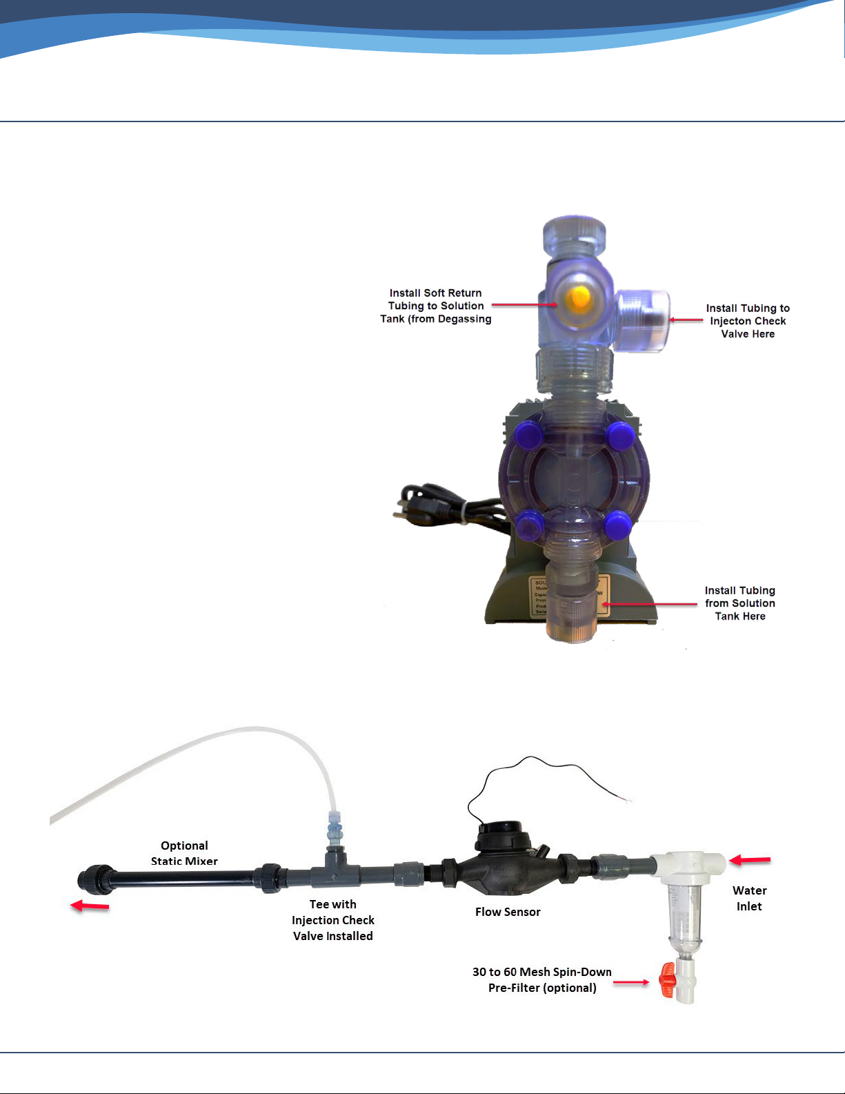
How Your Citric Acid Injection System Works
Install the Flow Sensor horizontally with the display facing up in a location where it is easy to
connect with the J-PRO-22and electrical outlet. Attach meter cable to pump per instructions
below. Whenever water ows through ow sensor, a precise amount of Citric Acid will
be injected.
Example Installation with Optional Contact Tank
Example Installation with Optional Static Mixer & Spin-Down Pre-Filter
www.cleanwaterstore.com 7
J-PRO-22 Proportional Citric Acid Installation Guide
Rev-042123
J-PRO-22 Installation Instructions
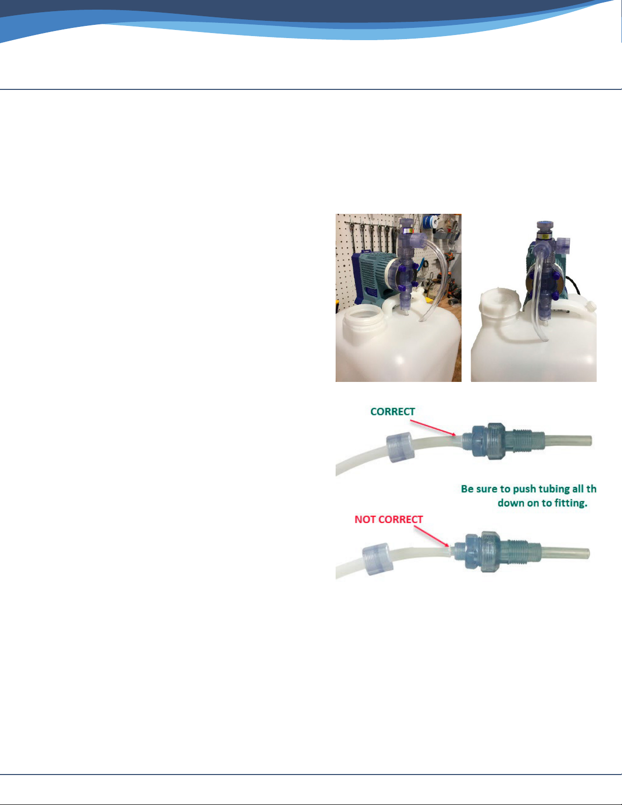
While you can mount the pump on a shelf above the solution tank, it is strongly advised to
mount the pump directly on top of the solution tank. If the tubing from the foot valve to the
suction side of the pump exceeds 60”, the unit will not have enough lift force to stay primed.
Mount Pump to Solution tank
Place pump on tank. Mark where the anchor holes
will be drilled. Drill pilot holes with a small drill bit
so that the pump can be mounted on the tank with
two wood or sheet metal screws.
We recommend screwing them in after the pump
has been primed and the tubing has been hooked
up for easiest installation.
Mark the holes for the suction tube and the
degassing return line and drill holes.
How to Connect Tubing
& Fittings
Note: Warming tube ends with hot water or a
hair dryer helps with tubing installation.
• Trim the end of the tubing square (cut with a
new box cutter blade).
• Slide the connector nut onto the tube.
• Push the tubing over the conical tting until the
tubing is ush against the end of the tting.
• Screw the connector nut on, hand tight.
• Do not use Teon tape/ paste on the tubing
tting connections.
Use the harder/stier translucent tubing for connection from discharge-side (12 o’clock)
to the injection check valve.
Use the softer clear tubing for the foot valve to suction-side (6 o’clock) connection.
www.cleanwaterstore.com 8
J-PRO-22 Proportional Citric Acid Installation Guide
Rev-042123
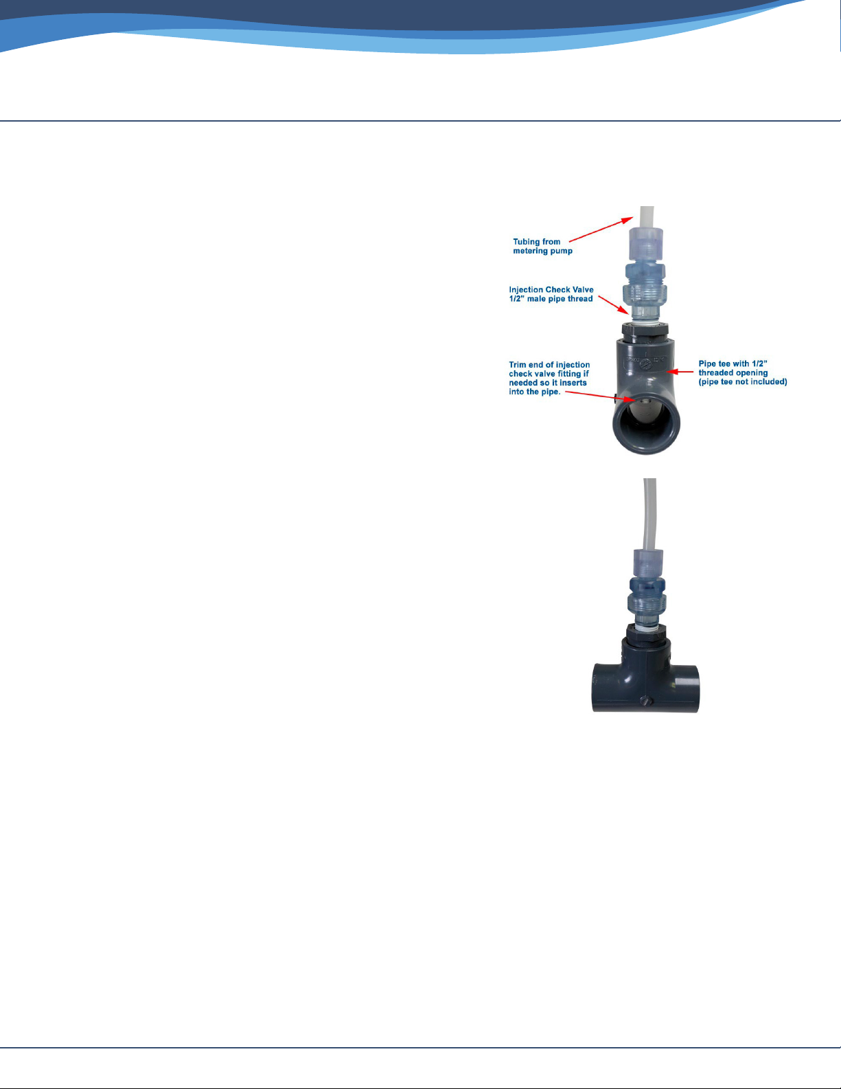
Install Discharge Side Tubing
This is the tubing that goes from the pump discharge
(outlet) to injection check valve in pipe tee.
1. Shut o well pump or water supply and de-pressurize
service pipe.
2. Install injection check valve by installing a pipe tee
in your pipe that has a ½” NPT tting, where you can
screw in the injection check valve (included with your
J-PRO-22 pump).
3. Wrap Teon tape on the ½” pipe threads of the
injection check valve and apply a light coating of white
Teon pipe paste and install into Tee tting.
4. Trim the end of the injection check valve tting so that
the end will be in the center of the service pipe.
5. Make sure to install injection check valve in to pipe
directly. If the end of the check valve is not in the
service pipe, it will not work. Do not install a ball valve,
or any length of pipe run, coming o the tee.
6. Using a hack saw or cutter, trim the end of the
injection check valve if needed, so it inserts into the
water pipe as shown.
7. Install tubing that came with your pump and connect
pump to injection check valve.
8. Cut tubing to desired length with enough slack to avoid kinks.
Injection check valve can be installed into PVC, copper or other piping.
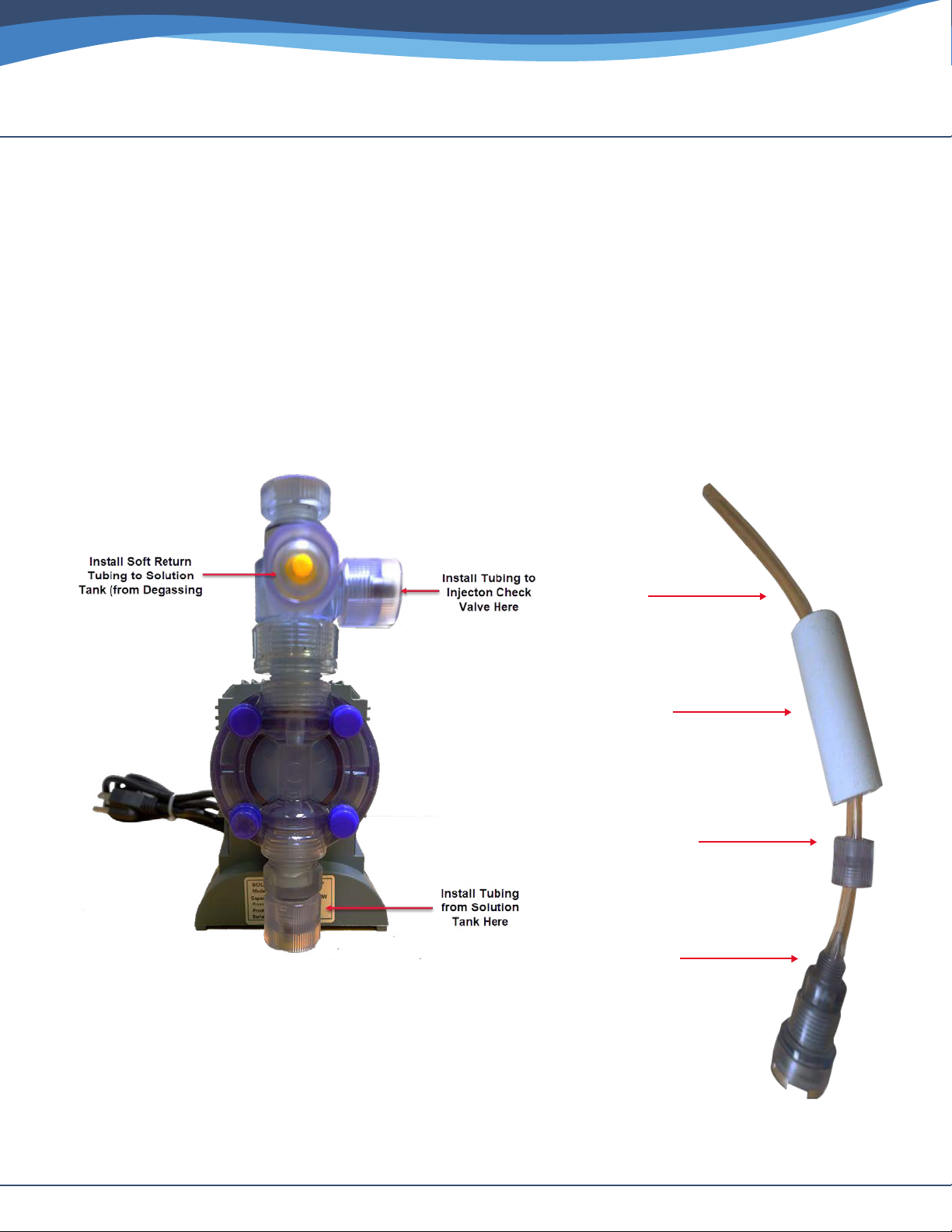
Suction
Ceramic
Connector
Foot
www.cleanwaterstore.com 9
J-PRO-22 Proportional Citric Acid Installation Guide
Rev-042123
Install Suction Tubing from Pump to Solution Tank
Connect hard tubing from foot valve in Solution Tank to Inlet/ Suction side of metering pump
1. Measure the tubing from the outside of the solution tank to ensure it will be 2-3” from the
bottom of the solution tank.
2. Do not allow weight to sit at the bottom of the tank. Connect tubing to the foot valve and put
the ceramic weight on.
3. Run the tubing up through the hole and connect to the Inlet/ Suction side of pump

www.cleanwaterstore.com 10
J-PRO-22 Proportional Citric Acid Installation Guide
Rev-042123
Connect Tubing from Degassing Port (“Kicker Port”)
You can use the soft tubing for this run, connect tubing to the degassing port tting (labeled on
the pump as “Kicker Port”) and pass tubing through the hole you drilled down into the tank 4-6”.

www.cleanwaterstore.com 11
J-PRO-22 Proportional Citric Acid Installation Guide
Rev-042123
Connect the Cables (wiring) for the J-PRO-22 Pump
1. Flow Meter Cable WHITE wire Connects to Pump Cable
RED wire (trim back, disregard other color wires)
2. Flow Meter Cable BLUE wire connects to Pump Cable
GRAY wire. (trim back, disregard other color wires)
3. Solder or connect the wires with wire nuts, or
electrical tape and then seal with shrink wrap or
electrical tape.
Prime & Start the Pump with
Water First
1. Add 4 gallons of distilled or puried or softened to solution tank.
2. Adjust the 2FV “kicker port” (which is the Degassing Valve) so it is open approximately ½ to 1
turn counter-clockwise.
3. Plug the pump in to electrical outlet.
4. Pump will be in Manual Mode, with the % at 100%
5. “Motor” light will be Green. “Auto” light will be o.
6. Press the ON-OFF button, pump will start pumping.
7. You will quickly see water being pumped up the suction tube and out the degassing tube.
8. After the pump is primed, close the degassing valve. The valve shall remained closed for
normal operation.
9. After the pump has been in operation for an hour or so, you should check the liquid end of
the pump (back end) and re-tighten the four stainless steel Allen-head screws on the head in
a crisscross fashion. Take care not to overtighten as you may damage the pump.

www.cleanwaterstore.com 12
J-PRO-22 Proportional Citric Acid Installation Guide
Rev-042123
Program and Pump Settings
NOTE: When making programming changes to the pump, you must wait at least 15 seconds for
the updated changes to be stored in the memory. Making additional changes or shutting o
power to the pump prior to this waiting period will default back to the original settings.
When rst plugged in, pump display will read “100” and be in Manual (non-pulse) mode.
“MOTOR” light will be green.
1. Press and hold the SET button for several seconds until “AUTO” light turns green.
2. Now press and hold both the SET button and UP Arrow button for a moment and release.
3. Using UP Arrow button only, adjust to 6, which gives you six pump strokes for each gallon of
water owing through the ow meter. If you get into negative numbers, you must scroll the
down arrow key to zero in order to scroll up to positive numbers.
4. After you have selected the number of strokes per gallon, press and release the Set button to
conrm the setting.
5. Finally press the ON-OFF button once, and now your pump is in automatic mode.
Note: Check to see if pump is operating correctly by running the water and comparing pump
actuations vs. programmed strokes per gallon of water owing through the meter.
During Auto mode, numbers appearing on the readout have no meaning or direct correlation to
amount of solution being injected.
Later you can adjust it higher (or lower) depending on the desired chlorine residual. For more
information on that, see example calculations below.
How to Select the Citric Acid Solution Strength and
Pump Setting
• The goal of a properly functioning Citric Acid injection system is to reduce the pH of your
water to the 7 to 8 pH range.
How Much Citric Acid Should Be Injected?
For citric acid, a good starting point is 1 lb of citric acid (2 cups) dissolved in one gallon of soft or
pure water. Warm water dissolves more rapidly.
Pulses Per Gallon setting on pump: Set to 6 to start.
Test the pH, and then either turn up the pump if the pH is not low enough, or add another 1/2
gallon of water if it is too low.

www.cleanwaterstore.com 13
J-PRO-22 Proportional Citric Acid Installation Guide
Rev-042123
Troubleshooting and Maintenance
Most problems occur with the connections, it can sometimes be hard to push the tubing onto
the cones, sometimes ttings are over-tightened, or people use Teon tape and paste on ttings
that do not need it.
Remember, above all, if the pump pumps in manual mode (makes a ka-thunk, ka-thunk sound),
then it works.
Is pH too Low? Too much Citric Acid?
Adjust the strokes per gallon down to 1 or 2, and/or make the Citric Acid solution more diluted
by adding more distilled water.
If you cannot get it to prime, it is either because a tting is too loose, too tight, or not
installed correctly.
If you see the water going up and down in the tubing, this indicates the foot valve is not tight, or
you installed the pump too high above the solution tank, or you mounted the pump improperly.
Sometimes, as mentioned earlier in the guide, it is because the four Allen head bolts on the
pump head have loosened, and need to be tightened, do not over-tighten.
If the solution has lled up the tubing, but it is not discharging, make sure the de-gas is opened,
and then close it until the point when it starts pumping.
The tubing going from the outlet/discharge to injection check valve will twitch
and move at the same time the pump triggers, that is how you can conrm you are
pumping solution.
If this does not work, remove the discharge-to-injection check valve tubing from the outlet
tting, and see if it strokes out of the top- if it does, this indicates that the problem is in the
injection check valve, or that you are trying to pump against greater than 100 psi.
Winterizing: do not let the J-PRO-22Pump or tubing freeze. If you need to winterize, drain the
Citric Acid solution tank and discard Citric Acid solution. Place the suction of the pump into a
bucket of clean water and allow the pump to run until the J-PRO-22Pump is free of any Citric Acid
solution. Remove the suction from the water and allow the pump to pump dry. Pump is ready to
store.
NOTE: when diluting the Citric Acid, use only distilled water, water from a reverse osmosis
system, or at least softened water. Do not use untreated well water.

P7007550
Injection
Check Valve
P7007540
Diaphragm
Replacement
P7007570
Foot Valve
www.cleanwaterstore.com 14
J-PRO-22 Proportional Citric Acid Installation Guide
Rev-042123
Need Assistance?
Call us at: 831-462-8500
Spare Parts
These installation parts are included with initial order, but you may wish to have spares on hand,
or replace the injection check valve, foot valve or diaphragm later.
Table of contents
Popular Water Pump manuals by other brands

Velp
Velp F30620198 instruction manual

Harbor Freight Tools
Harbor Freight Tools Drummond 63320 Owner's manual & safety instructions

Giant
Giant GP7622 Operating instructions/ repair and service manual

GORMAN-RUPP
GORMAN-RUPP SUPER T SERIES Installation, operation and maintenance manual

KSB
KSB Rotex Installation & operating manual

Beretta
Beretta Hydro Unit M Installation and owner's manual


Grundfos
Grundfos CM series Installation and operating instructions

WITA
WITA HE OEM 4 40 Series operating instructions

SFA
SFA SANICOM 1 installation instructions

STA-RITE
STA-RITE PNB-1L owner's manual

Grundfos
Grundfos UNILIFT AP35B Installation and operating instructions

Kamoer
Kamoer KSP-F01A-DC user manual