Cleanburn Sonderskoven Inset 5 User manual

JINHCN05 RevE 22/07/14
Sønderskoven Inset 5
Installation and Operating Instructions

JINHCN05 RevE 22/07/14
SØnderskoven Inset 5
Technical Specification
SØNDERSKOVEN INSET 5
Cleanburn Stoves, Unit 6,
Old Mill Industrial Estate, EX5 4RJ
BS/EN 13229
UKAS# 0692
Stove Mass: 100 kg
NOMINAL OUTPUT: 4.9 KW
CO Emission at 13% O2: 0.19%
Mean Flue Gas Temperature: 292°C
EFFICIENCY: 77.1%
Flue Gas Mass Flow: 4.3 g/s
Minimum clearance to combustible material
Top of Fire Surround:
200mm
Side of Fire Surround:
150mm
Side Wall:
300mm
This appliance is suitable for intermittent burning
This appliance is not suitable for use in a shared flue
Read and follow the operating instructions
Use only recommended fuels
This stove has been designed and assembled so that it may be used to burn wood logs in a Smoke
Control Area.
Find out if you are in a Smoke Control Area by contacting your Local Authority.
The SØnderskoven Inset 5 has been fitted with a permanent bypass that prevents closure of the
secondary air slider. Removal of this will lead to the appliance potentially causing smoke emissions.
Without the permanent bypass in place the appliance is not an exempt appliance and so may leave
the householder liable for a fine up to £1000.
12

JINHCN05 RevE 22/07/14
General Guidance
It is important that your stove is correctly installed
as Cleanburn Stoves cannot accept responsibility
for any fault arising through incorrect use or
installation.
These instructions cover the basic principles to
ensure satisfactory installation of the stove,
although detail may need slight modification to
suit particular local site conditions.
The installation must comply with current Building
Regulations, national and European standards,
Local Authority byelaws and other specifications or
regulations as they affect the installation of the
stove.
The Building Regulations requirements may also be
met by adopting the relevant recommendations in
the current issues of British Standards BS 8303 and
BS EN 15287-1.
COMPETENT PERSONS SCHEME
Cleanburn Stoves recommend that this stove is
installed by a member of an accredited competent
persons scheme e.g. HETAS.
If the installer is not a member of a competent
persons scheme, it is a legal requirement to notify
your local building control body in advance of any
work starting.
HEALTH AND SAFETY PRECAUTIONS
Special care must be taken when installing the
stove such that the requirements of the Health and
Safety at Work Act are met.
HANDLING
Adequate facilities must be available for loading,
unloading and site handling.
FIRE CEMENT
Some types of fire cement are caustic and should
not be allowed to come into contact with the skin.
In case of contact, wash immediately with plenty
of water.
ASBESTOS
This stove contains no asbestos. If there is a
possibility of disturbing any asbestos in the course
of installation then please seek specialist guidance
and use appropriate protective equipment.
METAL PARTS
When installing or servicing this stove, care should
be taken to avoid the possibility of personal injury.
MODIFICATION
No unauthorized modification of this appliance
should be carried out.
Safety
WARNING –This appliance will be hot when in
operation and due care should be taken. The
supplied gloves may be used to open the door and
operate the air controls.
AEROSOLS
Do not use an aerosol spray on or near the stove
when it is alight.
FIREGUARDS
Always use a fireguard in the presence of children,
the elderly or the infirm. The fireguard should be
manufactured in accordance with BS8423 –
Fireguards for use with solid fuel appliances.
DO NOT OVER-FIRE
It is possible to fire the stove beyond its design
capacity. This could damage the stove so watch for
signs of over-firing. If any part of the stove starts
to glow red, the stove is in an over-fire situation
and the controls should be adjusted accordingly.
Never leave the stove unattended for long periods
without first adjusting the controls to a safe
setting. Careful air supply control should be
exercised at all times.
FUME EMISSION
Properly installed and operated, this appliance will
not emit fumes. Occasional fumes from de-ashing
and refueling may occur. Persistent fume emission
must not be tolerated.
This appliance should not be operated with the
doors open
If fume emission does persist then the following
action should be taken immediately;
Open Doors and windows to ventilate room.
Let the fire out, or eject and safely dispose of
fuel from the appliance.

JINHCN05 RevE 22/07/14
Check for flue/chimney blockage and clean if
required.
Do not attempt to relight the fire until the cause
has been identified and corrected.
If necessary seek professional advice.
ADVERSE WEATHER
In a small number of installations, occasional local
weather conditions (e.g. wind from a particular
direction) may cause downdraught in the flue and
the stove to emit fumes. In these circumstances the
stove should not be used. A professional flue
installer will be able to advise on solutions to this
problem (e.g. anti-downdraught cowl).
DO NOT FIT AN EXTRACTOR FAN IN THE SAME
ROOM AS THIS APPLIANCE.
IN THE EVENT OF A CHIMNEY FIRE -
Raise the alarm
Call the Fire Brigade
Close appliance air controls
Move furniture, ornaments etc away
Place a fireguard in front of stove
Check the chimney breast for signs of excessive
heat.
If the wall is becoming excessively hot, move
furniture away. Ensure the Fire Brigade can gain
access to your roof space in order to check for fire
spread.
Chimney
Please check the suitability of any
fireplace/surround for closed solid fuel appliances
before installing this appliance. Cleanburn Stoves
Ltd cannot be held responsible for any fault arising
through incorrect use or installation.
Fire surround back panels suitable for solid fuel are
usually in three sections and slabbed. Many fire
surrounds are suitable only for use with gas and
electric fires and therefore not suitable for solid
fuel.
This product is designed to fit into a standard 16
inch fireback. An adaptor for flexible flue liners
(150mm) is also available if required. The upper
section of the fireback may need to be removed to
fit the flue adaptor. The chimney height and the
position of the chimney terminal should conform to
Building Regulations.
Check that the chimney is in good condition, dry,
free from cracks and obstructions. The diameter of
the flue should not be less than 150mm and not
more than 230mm. If any of these requirements are
not met, the chimney should be lined by a suitable
method.
The chimney must be swept before connection to
the stove.
Where the chimney is believed to have previously
served an open fire installation, it is possible that
the higher flue gas temperature from the stove may
loosen deposits that were previously firmly
adhered, with the consequent risk of flue blockage.
It is therefore recommended that the chimney is
swept a second time within a month of regular use
after installation.
If you have any doubts about the suitability of your
chimney, consult your local dealer/stockist.
If there is no existing chimney then either a
prefabricated block chimney in accordance with
Building Regulations Approved Document J, or a
twin-walled insulated stainless steel flue to BS4543
can be used. These chimneys must be fitted in
accordance with the manufacturer’s instructions
and Building Regulations.

JINHCN05 RevE 22/07/14
Flue Draught
If the flue draught exceeds the recommended
maximum, a draught stabiliser must be fitted so
that the rate of burning can be controlled and to
prevent over firing.
If the reading is less than the recommended
minimum then the performance of the appliance
will be compromised.
The flue draught should be checked under fire at
high output.
Minimum Draught –1.2mm Water Gauge
Maximum Draught –2.5mm Water Gauge
Connection to the Chimney
The gap between the old fireplace and stove flue
outlet must be filled in so that there is a smooth
streamlined entry into the flueway.
It is essential that all connections between the
stove and chimney-flue are sealed and made
airtight.
Both the chimney and any flue pipe must be
accessible for cleaning and if ANY parts of the
chimney cannot be reached through the stove (with
baffle removed), a soot door must be fitted in a
suitable position to enable this to be done.
Air Supply
Where necessary, any air opening must be kept
clear of blockage or obstruction. Due consideration
should be given to air requirements for any other
appliances in the same room or space.
Material Clearances
Any non-combustible walls within 50mm of this
appliance should be at least 200mm thick and
should extend 300mm above the top of the
appliance and at least 1.2 metres above the hearth.
Any walls more than 50mm from the appliance may
be reduced to a thickness of 75mm. Ensure the
inter-connecting flue pipe also has adequate
clearances to combustible materials.
A hearth with a minimum thickness of 125mm
should be provided. The hearth should extend to at
least 300mm in front of the stove and 150mm at
the sides, and should be in accordance with the
current building regulations.
In all instances the hearth and fireplace recess
should be made of non-combustible material.
The appliance shall be installed on a floor with
adequate load-bearing capacity. If the existing
construction does not meet this prerequisite,
suitable measures (e.g. load distributing plate)
should be taken to achieve it.
Minimum Distances to Combustible Material
Above the stove
200mm
At the side of the stove
150mm
Nearest Side Wall
310mm
In front of the stove
900mm
Note: combustible material refers to any material
that will degrade when subjected to heat (e.g.
plaster)
FIREPLACE DIMENSIONS
(Fire surround and side wall shown are combustible
and all dimensions stated are minimum)

JINHCN05 RevE 22/07/14
APPLIANCE DIMENSIONS
Removing Internal Components
All internal components must be removed prior to
fitting the stove. This will make handling the stove
easier; allow access to fixings and the flue outlet;
as well as protect the internal components from
damage during the installation process.
1. Open the door(s) and remove the ashpan.
2. Remove the fuel retainer by lifting the right-
hand side until it will clear the opening and
remove.
3. Remove the catch bar / front plate by lifting
the right-hand side until it will clear the
opening and remove.
4. Remove the grate bars by lifting them away
from the cam bar and pulling forward out of
the rear grate support. The singular bars
should be removed first, noting their positions
(low or high), leaving the two static triangular
bars to last.
N.B. When re-installing, the side bars need to
be installed first, followed by the singular
bars. The final two grate bars should be
installed at the same time for ease of fit.

JINHCN05 RevE 22/07/14
5. Remove the cam bar by firstly sliding it to the
right until the left hand end is clear of the hole.
6. Then maneuver the free end into the void in
the front left of the stove.
7. Slide the cam to the left until the right hand
side is clear of the hole, then raise one side
and swing out through the door opening.
8. Remove the ash barrier by sliding out of the
stove.
9. Remove the baffle by lifting and tilting one
edge so it can be lowered into the firebox and
removed.
10. Remove one of the upper side bricks by lifting
it out of its support on the tertiary air bar, and
lowering it into the firebox. (Note: at this
stage only remove one of the upper side
bricks.)

JINHCN05 RevE 22/07/14
11. Remove the upper rear brick by lowering it
down into the firebox and out.
12. The second upper side brick can now be
removed.
13. Remove the lower side bricks by lifting the
brick until the bottom edge can clear the
support bracket. Then tilt slightly into the
firebox and lower out from behind the tertiary
air bar.
14. Remove the lower rear brick by tilting the top
edge into the firebox and lifting out.
Installing the Stove
1. Unpack the stove.
2. Remove internal components.
3. Move the stove into position inside the
fireplace opening being careful not to damage
the hearth or paintwork on the stove and
making sure that the rope seal is compressed
forming a tight seal between the stove and
fireplace.
4. Drill into the existing fireback through the
fixing holes in the body, (see below) using a
6mm drill bit.
5. Place the screws provided into the fixing holes
and gently tighten until the stove feels secure.
6. Fill the fixing holes with fire cement to form an
airtight seal.
7. Seal the area where the throat meets the flue
outlet of the stove with fire cement.
8. Refit the internal components.
FIXING HOLES
Rear View

JINHCN05 RevE 22/07/14
Commissioning and Handover
Upon completion of the installation, allow a
suitable period of time for any fire cement and
mortar to dry out. A small fire may then be lit and
checked to ensure the smoke and fumes are taken
from the stove up the chimney and emitted safely
to atmosphere. Do not run the stove at full output
for at least 24 hours.
On completion of the installation and
commissioning, ensure that the operating
instructions and operating tools for the stove are
left with the customer. Advise the customer on the
correct use of the appliance with the fuels likely to
be used on the stove and warn them to use only the
recommended fuels for the stove.
Advise the user on what to do should smoke or
fumes be emitted from the stove.
The user should be warned to use a fireguard to BS
6539 in the presence of children, aged and/or
infirm persons.
Operating Instructions
Read the ‘General Guidance’ Section at the start
of these instructions before operating your stove
for the first time.
Allow sufficient clearance between the stove and
pictures, plasma screen televisions or ornaments
etc, as these could be damaged and could
potentially create a fire hazard (For more
information read the ‘Material Clearance’ section
of these installation instructions).
WARNING –This appliance will be hot when in
operation and due care should be taken. The
supplied operating tool or gloves may be used to
open the door and operate the air controls.
AEROSOLS
Do not use an aerosol spray on or near the stove
when it is alight.
AIR CONTROLS
Installed and used correctly this stove will burn
cleanly and efficiently. Therefore, to avoid the
disappointment of poor performance, please
familiarize yourself with the controls and their
recommended settings before use.
PRIMARY AIR
The slider at the bottom of the stove controls the
primary air. This provides a conventional air
draught to the bed of the fire. The control is open
when the slider is fully to the right.
SECONDARY &TERTIARY AIR
Secondary air is controlled via the slider above the
door(s), it is this “Airwash” that keeps a clean and
uninterrupted view of the fire.
Tertiary air is fixed and enters the stove through
the holes on the side of the firebox. It aids in good
secondary combustion and reduces emissions into
the chimney and environment.
SHUT
OPEN
SHUT
OPEN
FIXING HOLES
Front View

JINHCN05 RevE 22/07/14
LOCOMOTIVE GRATE
Your Cleanburn Stove is fitted with a locomotive
type grate. So that de-ashing can be carried out
cleanly and easily, it is riddled from the outside of
the stove with the doors closed.
BURNING WOOD
For optimal performance when burning wood,
open the grate by pushing the operating tool away
from you.
LIGHTING
We recommend that you have two or three small
fires before you operate your stove to its
maximum heat output. This is to allow the paint
to cure in steadily and to give a long service life to
the paint finish. During this curing in process you
may notice an unpleasant smell. It is non-toxic,
but for your comfort we would suggest that
during this period you leave all doors and
windows open.
Open both air controls fully and light one or two
firelighters placed centrally on the grate, allowing
the flames to become established before placing
several pieces of small dry kindling in a criss-cross
fashion above the firelighters, taking care not to
smother the fire. Close the stove door. Once the
kindling is well alight open the door and build the
fire by gradually adding slightly larger pieces of
wood, closing the door afterwards.
Once the fire is established close the Primary Air
Control (slide control fully to your left) and add
more fuel as necessary. The Secondary Air Control
can be used to regulate the burn rate of the stove.
Should the fire fail to light correctly open the door
and use a poker to spread the fuel across the
bottom of the firebox. Close the door and allow
the fuel and stove to cool before attempting to
relight the fire.
N.B. Leaving the air controls in the closed position,
adding too much fuel or using wood that is wet or
too large will prevent the fire from establishing
correctly and may result in smoke emission from
the stove.
When the stove is up to operating temperature
the operating tool or gloves should be used to
operate the air controls.
REDUCED COMBUSTION
In order to shut down the stove, reduce the
primary and secondary air by sliding both controls
to the left.
If the controls are left in this position, the fire will
be starved of air and will die down.
If you want to revive the fire it is recommended
that the primary air control is opened first, and
then the secondary air control.
Warning!- The stove will remain hot for a
considerable time after the fire has been
extinguished.
THE CLEAN AIR ACT 1993 AND SMOKE
CONTROL AREAS
Under the Clean Air Act 1993 local authorities may
declare the whole or part of the district of the
authority to be a smoke control area. It is an
offence to emit smoke from a chimney of a
building, from a furnace or from any fixed boiler if
located in a designated smoke control area. It is
also an offence to acquire an "unauthorised fuel"
for use within a smoke control area unless it is
used in an "exempt" appliance ("exempted" from
the controls which generally apply in the smoke
control area).
The Secretary of State for Environment, Food and
Rural Affairs has powers under the Act to
authorise smokeless fuels or exempt appliances
for use in smoke control areas in England. In
Scotland and Wales this power rests with Ministers
in the devolved administrations for those
countries. Separate legislation, the Clean Air
(Northern Ireland) Order 1981, applies in Northern
Ireland. Therefore it is a requirement that fuels

JINHCN05 RevE 22/07/14
burnt or obtained for use in smoke control areas
have been "authorised" in Regulations and that
appliances used to burn solid fuel in those areas
(other than "authorised" fuels) have been
exempted by an Order made and signed by the
Secretary of State or Minister in the devolved
administrations.
Further information on the requirements of the
Clean Air Act can be found here:
http://smokecontrol.defra.gov.uk/
Your local authority is responsible for
implementing the Clean Air Act 1993 including
designation and supervision of smoke control
areas and you can contact them for details of
Clean Air Act requirements.
The SØnderskoven Inset 5 has been recommended
as suitable for use in Smoke Control Areas when
burning wood logs.
REFUELLING
Add the new fuel to the fire and open both air
controls fully to allow flames to establish on the
new fuel. Once the fire is established and the logs
are blackened, set the primary air control to its
closed position and adjust the secondary air to
give the desired heat output. Never leave the
stove unattended until you are certain that the
flames are fully established.
Avoid refuelling on to a low firebed as this may
cause excessive smoke emission. Ensure there are
sufficient embers to ignite the new fuel rapidly.
Alternatively add some more kindling before
adding larger pieces of firewood.
Do not add firewood above the level of the tertiary
air inlets on the sides of the stove. Exceeding this
amount can result in the production of excessive
smoke.
RECOMMENDED FUELS
Cleanburn Stoves recommend that wood logs are
burnt in this appliance.
To achieve optimum efficiency, do not exceed a
maximum fuel load of 1.6Kg.
Burn only dry, well-seasoned wood, which should
have been cut, split and stacked for at least 12
months, with free air movement around the sides
of the stack to enable it to dry out. The wood
should have a moisture content not exceeding
20%.
Burning wet or unseasoned wood will create tar
deposits in the stove and chimney and will not
produce a satisfactory heat output.
Only authorised smokeless fuels may be used in
smoke control areas.
Warning! - Petroleum coke fuels or household
waste must not be burnt on this appliance. This
appliance must not be used as an incinerator.
Should any difficulties arise over fuel quality or
suitability, consult your local approved coal
merchant or:
HETAS Ltd –Telephone 01242 673257 –
www.hetas.co.uk
Solid Fuel Association –Telephone 0800 600 000 –
www.solidfuel.co.uk
General Maintenance
Important! –In order to ensure continued
compliance with current Building Regulations and
Local Authority Byelaws, this appliance requires
regular maintenance of the following –
N.B. Refer to the ‘Removing Internal Components’
section of the installation instructions for details
on how to remove each component.
PERIODS OF PROLONGED NON-USE
If the stove is to be left unused for a prolonged
period, then it should be given a thorough clean to
remove ash and unburned fuel residues. To enable
a good flow of air through the appliance to reduce
condensation and subsequent damage, leave the
air controls fully open.

JINHCN05 RevE 22/07/14
If the appliance has been unused for a long period,
such as during the spring and summer months, a
competent person should check the chimney for
potential obstructions before lighting the stove i.e.
get the chimney swept before the start of the
heating season.
AS NECESSARY
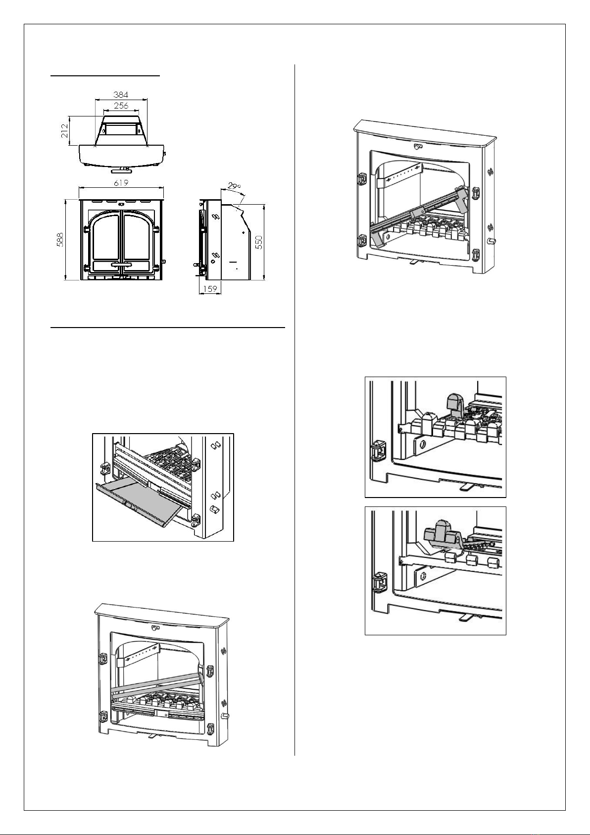
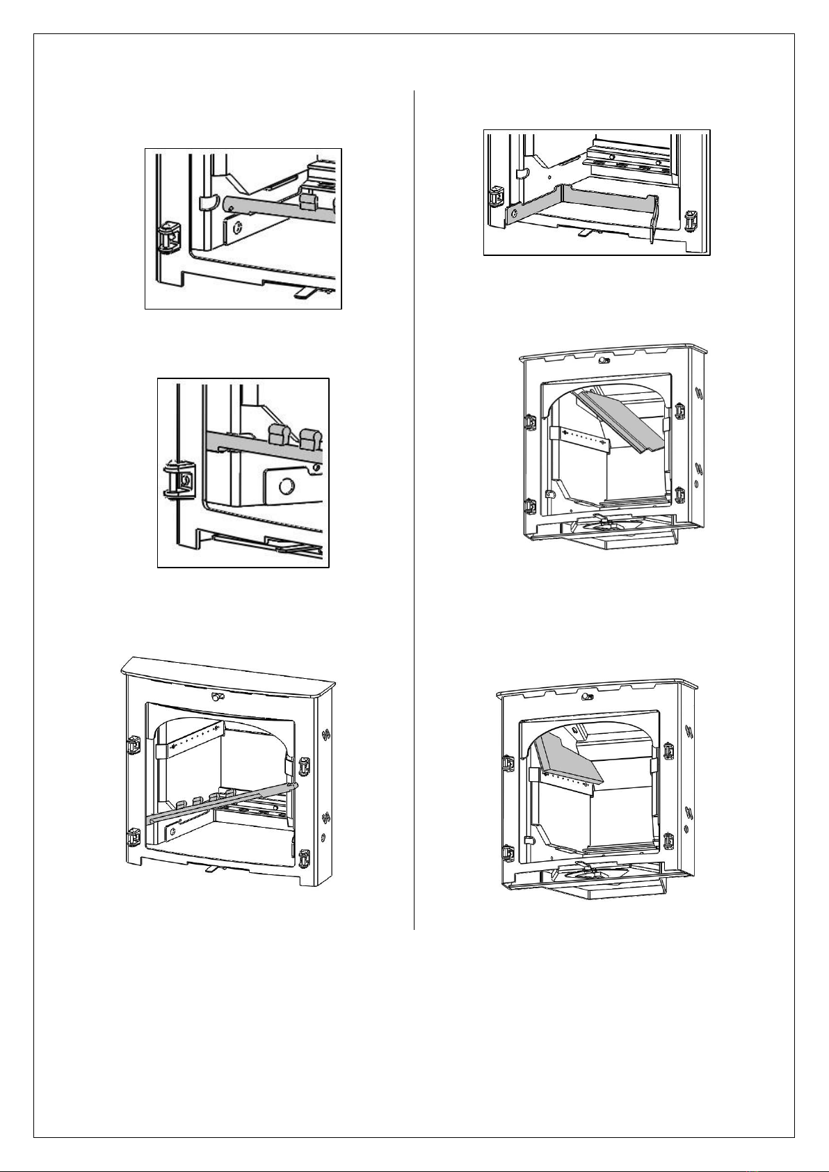
Baffle-This should be removed and cleaned at
least once a month to prevent any build up of soot
or fly ash that could lead to blocked flueways and
dangerous fume emission.
If the baffle is removed the chimney/flueway can
be swept through the appliance.
Stove body –the stove is finished with a heat
resistant paint and this can be cleaned with a soft
brush. Do not clean the stove whilst it is hot; wait
until it has cooled down. The finish can be
renovated with proprietary stove paint.
Glass Panel(s) - Clean the glass panel when cool
with proprietary glass cleaner.
Highly abrasive substances should be avoided as
these can scratch the glass and make subsequent
cleaning more difficult.
Wet logs on heated glass, a badly aimed poker or
heavy slamming of the door could crack the glass
panel.
The glass will not fracture from heat.
Firebricks -In normal use, these can last for many
years. It is possible however, to crack them if logs
are continually jammed against them or if they are
frequently struck with a poker.
Check periodically for seriously cracked bricks,
which can be replaced with new, available from
your dealer.
Door Catch -The door catch may require
adjustment to maintain the door seal. To adjust
the catch, follow the procedure below;
Loosen the M6 grub screw.
Rotate the catch shaft one complete turn to
achieve the correct door operation.
Tighten the grub screw.
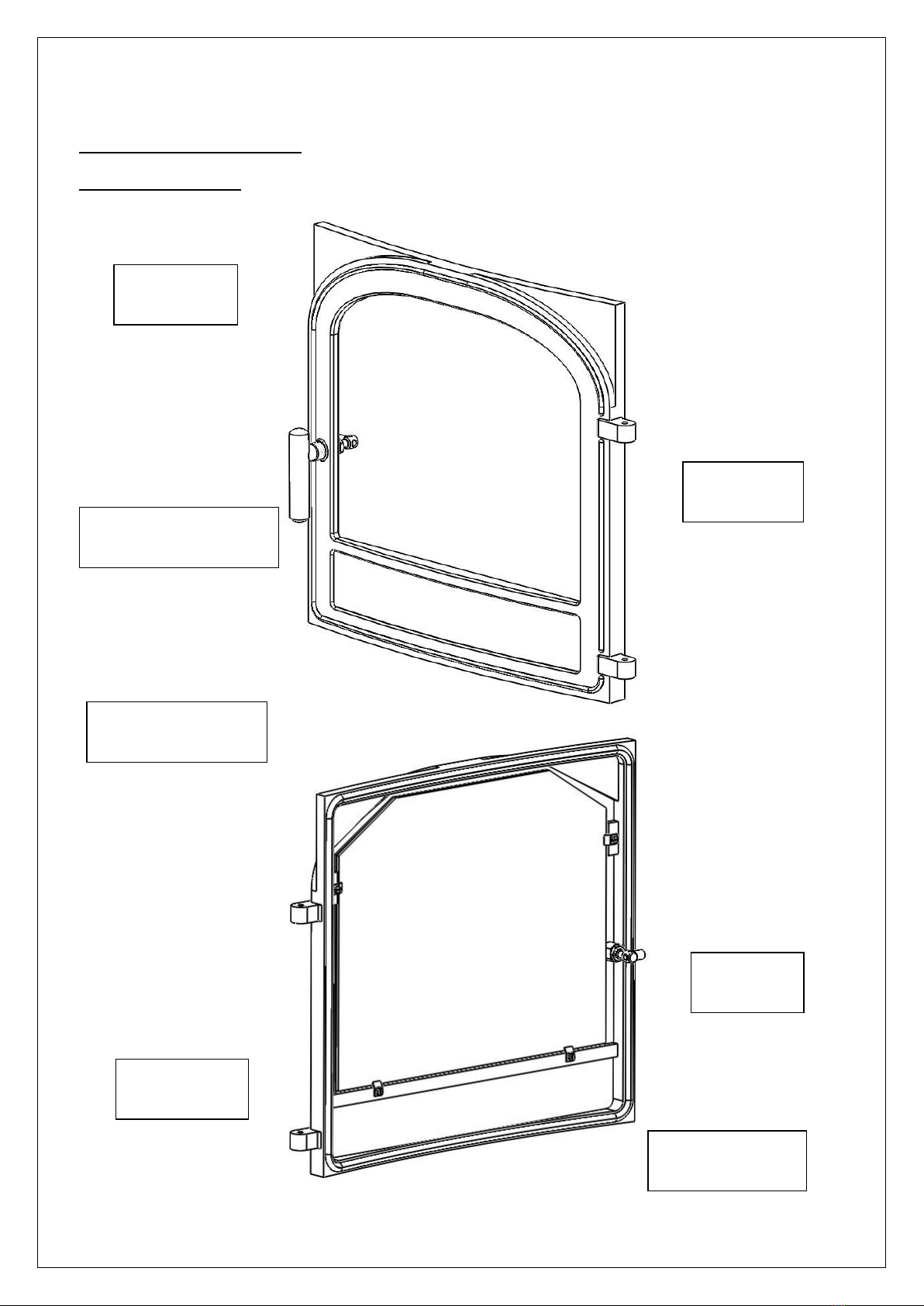
Rope - Check the rope around the door. If rope is
becoming detached, use Cleanburn Stoves rope
glue to reattach it. If the rope is in a poor
condition, a replacement rope kit may be ordered
from the Cleanburn Stoves spares range.
Chimney & Flueways - It is important that the
chimney, flueways and any connecting flue pipe
are swept regularly. This means at least once a
year for smokeless fuels and at least twice a year
for wood and other fuels.
The baffle will need to be removed from its
supports in order to sweep the chimney (see
‘Removing internal components’ instructions).
Only wire-centred sweeps’ brushes fitted with a
guide wheel should be used.
If it is not possible to sweep all parts of the
chimney through the appliance, ensure there is
adequate access to cleaning doors.
Seasonal use - If the appliance has been unused
for a long period of time, such as during the spring
and summer months, the chimney should be
checked for potential obstructions by a competent
person before lighting the stove.
Gaskets - all gaskets used on this appliance are
produced from a heat resistant material called
Manniglas. The glass gasket will have to be
replaced when a new piece of glass is fitted as the
gaskets become brittle after firing the stove. Over
time you may find that the gasket changes colour.
This is due to a reduction in the pigment used in
the manufacture of the product and no cause for
concern.
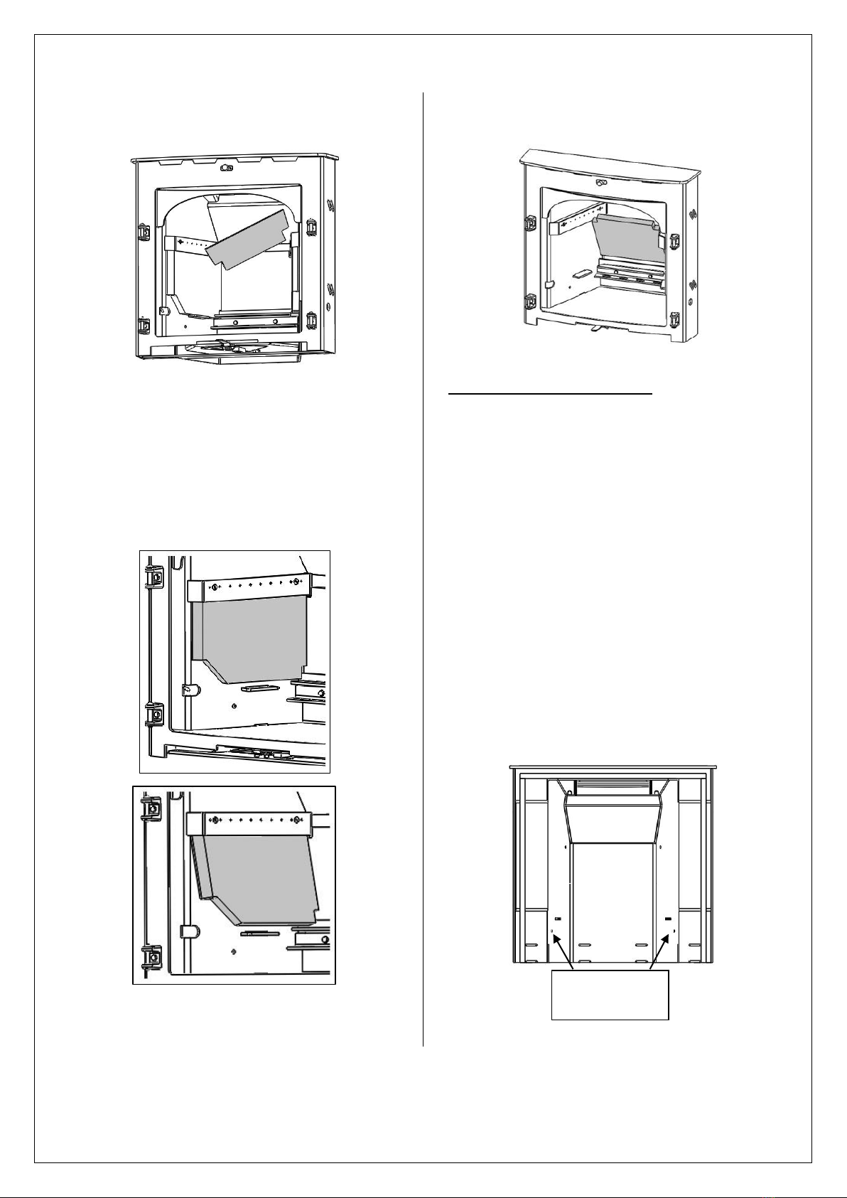
De-ashing –De-ashing should be carried out on a
regular basis to avoid a build up of ash and ensure
sufficient primary air flow. Empty the ashpan
regularly to prevent ash reaching the underside of
the great bars. At least every month remove the
ash barrier (see section ‘Removing Internal
Components’) and remove excess ash with a
vacuum cleaner.

JINHCN05 RevE 22/07/14
Primary Air Valve –The primary air valve can be
removed from the stove. To do this first remove
the Ashpan, Fuel Retainer, Grate Bars and Cam Bar
(see section ‘Removing Internal Components’ of
these instructions). This will allow you to gain
access to the two countersunk socket set screws in
the base.
Undo these screws until you feel a resistance. If
the screws have lifted up out of the base when
both have been undone, push them back down so
the screw heads are flush with the base. By
undoing the screws you are allowing the valve
release plate to move into its lowered position.
Once the valve release plate is its lowered position
as shown above the primary air valve can be
removed by lifting the handle until the locating pin
is released and pull out of the stove.
To install the primary air valve, slide the valve in
centrally until you hear the locating pin click into
place. There is a back stop to help guide the valve
into place. Check fit by opening and closing the
valve. Once you are happy with the fit, tighten the
two countersunk socket set screws in the base
until the valve release plate is in its upper position.
Check that the valve can no longer be removed.
Re-install the Cam Bar, Grate Bars, Fuel Retainer
and Ashpan.
Trouble Shooting
FIRE WILL NOT BURN
Check that –
Chimneys and flueway are clear.
A suitable fuel is being used.
There is an adequate air supply into the room.
An extractor fan is not fitted in the same
room.
Flue draught is above minimum level (see
installation instructions).
FIRE BLAZING OUT OF CONTROL
Check that –
The door is tightly closed.
The air controls are in the closed position.
A suitable fuel is being used.
The glass is not loose.
The door rope seal is in good condition.
Flue draught is below maximum level (see
installation instructions).
Primary Air Valve Release Screws
Valve Release Plate in lowered position
Valve Release Plate in upper position

JINHCN05 RevE 22/07/14
Spares Information
SINGLE DOOR SPARES
SINGLE DOOR
HCE09/008
DOOR GLASS
HCE09/102
ROPE SEALING KIT
SCPCB900SDRSK-REVC
DOOR CATCH ASSEMBLY
HCE09/ARRT/043
GLASS CLIP
HHR08/046
GLASS CLIP SCREW
FSJM05008SS
GLASS GASKET
HCE09/101

JINHCN05 RevE 22/07/14
DOUBLE DOOR SPARES
LEFT HAND DOOR
RIGHT HAND DOOR
RIGHT HAND DOOR
HCE09/009
DOOR HANDLE
HCE09/033
DOOR GLASS
HCE09/031
GLASS GASKET
HCE09/030
DOOR CATCH
ASSEMBLY
HCN05/ARRT/031
ROPE SEALING KIT
SCPCB900DDRSK
GLASS CLIP SCREW
FSJM05008SS
GLASS CLIP
HHR08/046
LEFT HAND DOOR
HCE09/010
GLASS CLIP
HHR08/046
GLASS CLIP SCREW
FSJM05008SS
GLASS GASKET
HCE09/030

JINHCN05 RevE 22/07/14
BODY ASSEMBLY SPARES
SLIDER KNOB
HCE06/059
BAFFLE
HCN05/022
REAR GRATE SUPPORT
HCN05/035
GRATE BARS
SIDE: CNN05/004 A&B
UPPER: CNS04/013
LOWER: CNS04/012
LOWER REAR BRICK
HCN05/025
UPPER REAR BRICK
HCN05/026
OPERATING TOOL
HFR07/040
PRIMARY AIR VAVLE
HCN05/ARRT/026
ASHPAN
HCN05/ARRT/033
CATCH BAR
SINGLE DOOR:
HCN05/ARRT/019
DOUBLE DOOR:
HCN05/ARRT/020
FUEL RETAINER
HCN05/ARRT/030
LOWER SIDE BRICK
HCN05/023
HINGE PIN
FRRE08-1.75
HINGE
HH06/050
UPPER SIDE BRICK
HCN05/024
TURBO BARS
HCN05/ARRT/022 A&B
Table of contents
Other Cleanburn Stove manuals
Popular Stove manuals by other brands

Vogelzang International
Vogelzang International BX42E owner's manual

Masport
Masport Geneva F39-NG Owners & installation manual

EdilKamin
EdilKamin MILLA H 15 Up Directions for installation, use and maintenance

Carina
Carina Wood Burning Stove Instructions for installation

Kooper
Kooper 5914189 manual

Vilpra Sauna
Vilpra Sauna GRANNUS VPR-8 Installation and operation manual