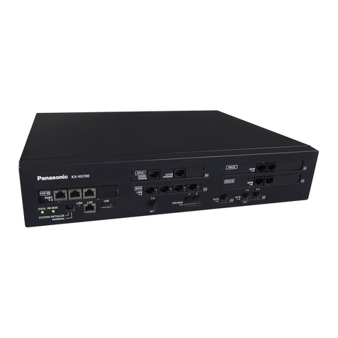
Clear-Com ECLIPSE TEL-14 User manual

CLEAR-COM ECLIPSE
TEL-14 TWO-CHANNEL TELEPHONE INTERFACE
I N S T R U C T I O N M A N U A L
Part Number: 399G278 Rev. A
30 November 2018

Document Reference
Clear-Com HelixNet Partyline User Guide
Part Number: 399G278 Rev A
Legal Disclaimers
Copyright © 2018 HME Clear-Com Ltd.
All rights reserved.
Clear-Com, the Clear-Com logo, and Clear-Com Concert are registered trademarks of HM Electronics, Inc.
The software described in this document is furnished under a license agreement and may be used only in
accordance with the terms of the agreement.
The product described in this document is distributed under licenses restricting its use, copying, distribution, and
decompilation/reverse engineering. No part of this document may be reproduced in any form by any means
without prior written authorization of Clear-Com, an HME Company.
This product is covered by U.S. Patent Nos. 8,311,085 and 8,553,865 and by European Patent No. 2 176 987 B1.
Clear-Com Offices are located in California, USA; Cambridge, UK; Montreal, Canada; and Beijing, China. Specific
addresses and contact information can be found on Clear-Com’s corporate website:
www.clearcom.com
Clear-Com Contacts
Americas and Asia-Pacific Headquarters
California, United States
Tel: +1.510.337.6600
Email: [email protected]
Europe, Middle East, and Africa Headquarters
Cambridge, United Kingdom
Tel: +44 1223 815000
Email: [email protected]
China Office
Beijing Representative Office
Beijing, P.R.China
Tel: +8610 65811360 / 65815577

iii
TEL-14 TWO-CHANNEL TELEPHONE INTERFACE
CONTENTS
OPERATION 1-1
Introduction.....................................................................................................1-1
Description......................................................................................................1-2
Operation ........................................................................................................1-6
INSTALLATION 2-1
Introduction.....................................................................................................2-1
Description......................................................................................................2-2
Wiring .............................................................................................................2-3
Setup ...............................................................................................................2-4
Configuration ................................................................................................ 2-14
MAINTENANCE 3-1
Introduction.....................................................................................................3-1
Troubleshooting ..................................................................................................... 3-1
Block Diagram ..................................................................................................... 3-4
SPECIFICATIONS 4-1
LIMITED WARRANTY 5-I
Warranty Period. . . . . . . . . . . . . . . . . . . . . . . . . . . . . . . . . . . . . . . . . . . . . . . 5-i
Technical Support . . . . . . . . . . . . . . . . . . . . . . . . . . . . . . . . . . . . . . . . . . . . . 5-i
Warranty Repairs and Returns...................................................................... . 5-ii
Non-Warranty Repairs and Returns ............................................................. . 5-ii
Extended Warranty............................................................................................ . . 5-ii
Liability . . . . . . . . . . . . . . . . . . . . . . . . . . . . . . . . . . . . . . . . . . . . . . . . . . . . 5-iii

iv
TEL-14 TWO-CHANNEL TELEPHONE INTERFACE
IMPORTANT SAFETY
INSTRUCTIONS
Please read and follow
these instructions
beforeoperating this
product.
1.
Read these instructions.
2.
Keep these instructions.
3.
Heed all warnings.
4.
Follow all instructions.
5.
Do not use this apparatus nearwater.
6.
Clean only with drycloth.
7.
Donotblockany ventilation openings. Install in
accordance with the
manufactur
er
’
s
instr
u
ctions.
8.
Donotinstallnearanyheatsourcessuchasradiators,heat
registers,stoves, or other apparatus (including amplifiers) that
produce heat.
9.
Only use attachments/accessories specified by the manufacturer.
10.
Use only with the cart, stand, tripod, bracket, or table specified
by the manufacturer, or sold with the apparatus. When a cart is
used, use caution when moving the cart/apparatus combination
toavoid injury from tip-over.
11.
Unplug this apparatus during lightning storms or when
unused for long periods of time.
12.
Refer all servicing to qualified service personnel. Servicing is
required when the apparatus has been damaged in any way,
such as power-supply cord or plug is damaged, liquid has been
spilled or objects have fallen into the apparatus, the apparatus
has been exposed to rain or moisture, does not operate normally,
or has been dropped.
13.
WARNING:
Toreducetheriskoffireorelectricshock,donot
exposethis product to rain ormoisture.
Please familiarize yourself with the safety symbols in Figure 1. When
you see these symbolson this product, they warn you ofthepotential
danger ofelectric
shock if the station is used improperly. They
also refer you to important operating and maintenance
instructions in the manual.

v
TEL-14 TWO-CHANNEL TELEPHONE INTERFACE
This symbol alerts you to the presence of uninsulated
dangerous voltage within the product's enclosure that might
be of sufficient magnitude to constitute a risk of electric
shock. Do not open the product's case.
This symbol informs you that important operating and
main- tenance instructions are included in the literature
accompanying this product.
Figure 1: Safety Symbols
EMC AND SAFETY
TheTEL-14TelephoneInterfacemeetsallrelevantFCC specifications
set out below:
EN55103-1Electromagnetic compatibility.Productfamilystandardfor
audio,
video, audio-visual, and entertainment lighting control
apparatus for professional use. Part 1: Emissions.
EN55103-2Electromagnetic compatibility.Productfamilystandardfor
audio,
video, audio-visual, and entertainment lighting control
apparatus for professional use. Part 2: Immunity.
ThisdevicecomplieswithPart15oftheFCCRules.Operationis
subjectto the following two conditions: (1) this device may not
cause harmful interference, and (2) this device must accept any
interference received, including interference that may cause
undesired operation.
RISK OF ELECTRIC SHOCK
DO NOT OPEN
CAUTION


TEL-14 TWO-CHANNEL TELEPHONE INTERFACE
1 - 1
1
This chapter describes
the five most common
modes of operation.
OPERATION
INTRODUCTION
This chapter describes how to use the TEL-14 two-channel auto-
nulling telephoneinterface. The TEL-14'spanel controlsand
internaloptionswitches can select any one of a large number of
modes of operation. This chapter describes the five most
commonmodes:
•
Intercom-station telephone access
•
Self-service dial-in
•
Manual call screening
•
Intercom-to-intercom
•
Party-line dial-in
Intercom station operators will normally access telephone lines with
the TEL-14
in
the
“inter
com-
station
te
le
phone-acce
ss
”
mode.
H
o
weve
r,
station
operators
may need to check with their system
operator for further instructions if a
TEL-14 has been configured in a mode not described here.
Technical personnel should refer to Chapter 2, “Installation,” for
details on configuring the TEL-14's internal option switches for each
of these modes (and any others possible).
The next section, “Description,” covers the basic features of the
TEL-14, including its front-panel controls and indicators. The option
switch settings are described for each mode, but they are covered
more thoroughly in Chapter 2. The final sections cover the use of
the TEL-14 in each of the five modes.
Important: When the TEL-14 is first connected to a new telephone
line, its automatic nulling process must be performed before it
can be used. This process consists ofcallingeachline,depressing
theAutoAnswerbuttonfor5
seconds, and then waiting several seconds
while the automatic procedure is
carried out. It may not be possible to
make outgoing calls on the telephone line until this procedure is
performed. Refer to the Automatic Telephone Line Null section of this
Operation Manual.
Note:
Otherconfigurationsarepossible,inadditiontotheconfigurations
described
here.However,certain configurations mayresult in undesirable
crosstalk, asa result of
thelimitationsoftheTEL-14'scircuitry.Forexample,
consideranewsreporterwho callsintothematrix.Youwouldliketoprovide
thereporterwithaprogram feed,and at the same time route his voice in
through the matrix toalive broadcast. However,
the TEL-14 cannot
perfectly isolate his talk from his listen, so some of his outgoing
program feed may leak into his incoming voice.

1 - 2
TEL-14 TWO-CHANNEL TELEPHONE INTERFACE
Install the TEL-14 in
an interface frame.
See the Interface
Frames Instruction
Manual for more
information.
Note: When using the TEL-14 with a speaker station, keep the panel mic gain
low. In
general, keep all gain controls set to a level which is acceptable, but not excessive.
DESCRIPTION
The TEL-14 telephone interface can be installed in an IMF-3 or
IMF-102 interface frame.
The TEL-14 allows two standard 2-wire POTS (Plain Old Telephone
Service) telephone lines to be connected to ports in the Eclipse
matrix. The TEL-14 can answer an incoming call automatically ("auto-
answer") after either 1 or 4 rings, and it can be configured to send a
call signal whenever it answers a call. The TEL-14 can be configured
to be accessible to intercom station operators, or only to outside
callers.
The front panel features for each telephone line a "ring/off-hook"
LED, a "hook" button, a"sendlevel"LED, a"send volume" control, a
"receive volume" control, an "auto gain adjustable" LED, an "auto
gain" button, an "auto gain fixed" LED, an "auto answer" LED, and
an "auto answer" enable button. For more details see the "Controls
and Indicators" section,below.
The TEL-14 occupies one slot in an interface frame. The TEL-14
provides transformer isolation betweeneachtelephonelineandthe
matrix.TheTEL-14 includesa"normallyopen"relay("A"and"A1"
contacts)foreachlinethatcloses when the line is in use (off hook).
Connections to the matrix are via RJ-45 connectors,and
connectionstothetelephonelineandexternalrelayconnections are
viaDB-9Mconnectors.Asecondarytelephonesetmaybeconnected
inseries with each TEL-14 line. Clear-Com provides DB-9F to RJ-
11 adapters (CC# 770025) that allow the use of common RJ-11
telephone jacks and cords.
CONTROLS AND INDICATORS
The front panel features:
•
A bicolor "ring/off-hook" status LED
•
A "hook" ("line seize")button
•
A bi-color "send level" LED
•
A "send volume" control
•
A "receive volume" control
•
An "auto gain" button
•
"Auto gain" status LEDs
•
An"auto answer" button
•
An "auto answer" statusLED

TEL-14 TWO-CHANNEL TELEPHONE INTERFACE
1 - 3
"Ring/Off-Hook" LED
The "ring/off-hook" LED flashes red when the telephone line
receives a ring signal.TheLEDisgreenwhilethelineisanswered
andinuse.TheLEDflickers yellow during the automatic hybrid
nulling process. The LED is off when the line is on-hook and not
ringing.
"Hook" Button
The "hook" button allows a local operator tomanually toggle the
TEL-14 line between "on-hook" (telephone line not in use) and "off-
hook" (line "seized" -- thatis,inuse)status. If alineisseizedatthe
interfacebythe"hook"button,that
line
cannot
be
r
e
leased
from
an
in
tercom
station,
ev
en
if
the
“
m
atrix
contr
o
l
”
option switch is set. The
line can be released only by either pushing the button again, orby
auto-disconnect (if the auto-disconnect option switches are set).
"Send Level" LED
Thebi-color"sendlevel"LEDlightsgreen whentheaudiosignal
beingsentto thetelephonelineisatatypicalacceptablelevel.The
LEDlightsredwhenthe audio output signal level is too high. In
normal operation, the LED should light
gr
een
du
ring
speech
and
only
flicker
r
e
d
intermittently.
The
“
s
end
v
olume
”
control adjusts the
level indicated by this LED.
"Send Volume" Control
The "send volume" control sets the level of the signal that the TEL-14
sends to the telephone line by changing the AGC limiting level. It is
only active when the
"autogain"buttonissetto“adjustable.” The"send
volume"controlhasarange
of 12 dB. Adjust the "send" control so that
the "send level" LED always lights green with no more than occasional
red flashes.
"Receive Volume" Control
The "receive volume" control sets the level of the signal that the TEL-
14 receives from the telephone line by changing the AGC limiting
level. It is only active
whenthe"autogain"buttonissetto“adjustable.”
The"receivevolume"control
hasa range of 12 dB.Whilesettingthe
receivevolume,listentotheoutputfrom
the
teleph
one
line
in
normal
use.
A
d
just
the
“
r
eceive
”
con
t
r
o
l
until
t
h
e
tel
e
phone
receive level is
comparable to the volume level of other intercom listenpaths.
"Auto Gain" Button
With the "auto gain" button set to fixed, the TEL-14 adjusts the audio
gain to limit the send and receive telephone line signals to normal
levels. In the fixed mode, the "send volume" and "receive volume"
controls are disabled, but are in effect set to their center positions.
When the "auto gain" button is set to
“
a
djusta
ble,”
the
TEL-14
adjusts
the
audio
gai
n
t
o
l
i
mit
the
send
an
d
r
eceive
telephone line signals to
levels defined by the "send volume" and "receive volume" controls.
The TEL-14 remembers the setting of the "auto gain" button when
power is turned off.

1 - 4
TEL-14 TWO-CHANNEL TELEPHONE INTERFACE
"Auto Gain" Status LEDs
The
s
e
gr
ee
n
and
yell
o
w
LEDs
ind
i
cate
t
h
e
curren
tly
se
lec
t
ed
“
a
uto
gain
”
mode
.
The
y
e
llo
w
LED
indicat
e
s
th
at
t
h
e
“
a
djustabl
e
”
m
o
de
is
selec
t
ed
and
t
h
e
gr
een
LED
indicates
that
the
“
f
ix
ed
”
mode
is
se
lec
t
ed.
R
e
f
e
r
to
the
pr
evious
paragraph
for an explanation of these modes.
"Auto Answer" Button
The
front-panel
“
a
uto
ans
w
er
”
button
al
lo
ws
t
h
e
loc
a
l
user
to
enable
or
disable
the
TEL-14's
auto
answering
mode.
The
“
a
uto
answ
er
”
function,
in
conjunction
with
th
e
“
a
uto
disconn
e
ct
”
function,
all
o
ws
a
TEL-14
t
o
autom
a
t
i
cally
s
e
r
v
ic
e
incoming calls. An outside caller can
automatically be connected to any matrix audio connection that has
been pre-assigned from the Eclipse Configuration System, such as a
party line or an IFB program feed.
Auto answer is enabled by using the "auto answer" button to turn ON
the auto answer indicator LED. The interface will then automatically
answer incoming calls after either 1 or 4 rings, as set by the "ring
count" option switch. The TEL-14 remembers the setting of the "auto
answer" button when power is turned off.
The
“
a
uto-answer
”
b
u
tton
can
b
e
o
v
erridden
b
y
t
h
e
Ecli
ps
e
matrix
to
allo
w
the TEL-14 to auto-answer without the auto-answer button
being set to enable.
This will occur when a TEL-14 is configured in ECS to use Passcodes
set up in
the
Sy
stem
P
r
efer
ences
“S
ystem
A
ccess
Codes
”
t
a
b
as
DTMF
P
a
ss
codes.
The
us
e
of DTMF passcodes is configured in Matrix
Hardware under Advanced Settings and DTMF Settings as “Enable
Passwords”.
Once a lineisauto answered, itcan onlybereleased byauto
disconnect, bythe "hook"button,orfromamatrixstationthathas
"remotetelephone-linerelease" enabled.Autodisconnectreleases
thelinewhenadialtone,busytone,reorder tone, or loop current
interruption appears on the line (if not disabled by the auto-
disconnect option switches). The line cannot be released by
deactivating any or all talk or listen paths from the intercom
stations to the TEL-14. Flash hook signals from the matrix will also
have no effect. This prevents intercom station operatorsfrom
disconnecting the telephone line when it is in automatic use by
outsidecallers,orinmanual use byanintercomstation operator
whohas access to the "hook"button.
The "auto answer" button can also be used to initiate an
automatic nulling sequence. Refer to the followingsection.
"Auto Answer" Status LED
This
gr
een
LED
in
dicates
the
curr
ently
s
e
lected
“
a
ut
o
an
sw
er
”
mode.
If
it
is
lit,
the TEL-14 will automatically answer telephone calls. If it is
not lit, incoming telephone calls can only be answered manually.
Refer to the previous paragraph for
fur
t
her
explanation
of
“
a
uto
answer
”
mode.

TEL-14 TWO-CHANNEL TELEPHONE INTERFACE
1 - 5
AUTOMATIC TELEPHONE LINE NULL
The TEL-14 features sophisticated automatic nulling circuitry, in addition
to its integral echo cancellation system. This nulling capability is in two
parts:
•
The initial telephone line hybrid null is to be performed the first
time a telephone line is connected to the TEL-14 or whenever a
different telephone line isconnected.Thisprocessisautomatic,
butmustbeinitiatedbythe user. The way to do this is described
later in this section.
•
The continuous dynamic voice null takes place during each
telephone call. It automatically "fine tunes" the null and cancels
echoes.
The TEL-14 must null itself to the telephone line before normal
operation is optimal. This procedure is to be performed once
whenever the TEL-14 is connected to a different telephone line.
Once this nulling procedure is performed, the TEL-14 will remember
the telephone line characteristics when it is removed from the frame
or loses power. It is necessary to null (minimize) the sidetone (the
sound of the operator's own voice in his or her headset) when an
external telephone line is placed in an intercom environment. Ideally,
there should be no portion of the talk signal in the listen signal. The
TEL-14's sidetone nulling procedure is described here.
Before calling the TEL-14 to automatically null it, connect the external
telephone line and any other devices that affect the line's impedance.
These include other telephone extensions connected in parallel on
the same line. The phone line must be active (turned on at the
central telephone office) during the nulling process, and all local
parallel phone sets must be plugged in but on-hook so the line is in
its normal operating state.
1.
Enable the "auto answer" function using the front panel button.
2.
CalltheTEL-14interfacefromastandardtelephonesetorcellular
phone.
Do not
call the TEL-14 from another TEL-14 in an
intercom.
3.
Press and hold the "auto answer" button for 5 seconds. The
green "auto answer on" LED will turn off and then turn on again
after 5 seconds. When this happens, release the "auto answer"
button.
4.
Maintainsilenceonthetelephoneline.TheTEL-14willlistenfor
onesecond ofsilencebeforebeginning.The"ring/off-hook"LED
willthenflickeryellow and a series of tones will appear on the
telephone line. These tones will be heard on thetelephoneline,
butnotonthe intercom. Maintain silence during this process.
5.
At the conclusion of the tones, the automatic nulling process is complete.
After this initial automatic nulling adjustment has been made, the
TEL-14 will remain adapted to this telephone line. There will be no
white noise or tones at the beginning of each call, but instead the
TEL-14 will use voices to dynamically adapt the interface to account
for any residual nulling which may be needed.
Typically, the TEL-14 will have adapted within 5 seconds of the start
of the call. Before it has adapted, voices may temporarily sound
hollow. This effect is normal, but may be minimized by reducing the
send and/or receive volume settings. Throughout the call the TEL-14
will continue to perform continuous, automatic echo cancellation and
adaptation to acoustic changes.

1 - 6
TEL-14 TWO-CHANNEL TELEPHONE INTERFACE
The above initial automatic nulling process should not need to be
repeated, unless the telephone line connection is changed to a
different telephone number or if there is reason to believe the
telephone line impedance has changed significantly--for example, if
echoing or feedback occurs at a lower volume setting than before.
OPERATION
Thissectiondescribestheoperationof theTEL-14ineachofthe
following modes:
•
Intercom-station telephone access
•
Self-service dial-in
•
Manual call screening
•
Intercom-to-intercom
•
Party-line dial-in
INTERCOM-STATION TELEPHONE-ACCESS
MODE
I
n
“i
ntercom-stat
ion
tel
e
phone-ac
ces
s
”
mode,
a
call
on
a
TEL-14
line
can be answered by any intercom station with a selector key
assigned to a TEL-14 port label. Intercom stations can originate a call
by using the "dial phone" mode.
Ifthe call must originate at another station model, then this station
must have a key programmed toactivate a DTMFsequence.
Anotherwaytoarrangethisis fortheoperatortohaveaccess to a
standard telephone set connected with the TEL-14line(forfurther
information, see "Manual CallScreeningOperation" below).
The
d
e
fault
settings
of
the
TEL
-
14
all
o
w
“
s
tati
on
ac
ces
s
”
mode.
I
f
the
“immediate
manual
disconnect
”
feat
ur
e
is
disab
le
d
,
t
h
er
e
will
be
a
pe
riod
of 15 seconds between the time when you deactivate the
path to the TEL-14 port and the time when the TEL-14 hangs up the
line. This gives you time to transfer the call to another station, or to
recover an accidental deactivation of the path to the TEL-14 without
losing the call.
If your station is on the "preset call signal list" for the TEL-14 port,
you will automatically receive a call signal whenever the TEL-14
answers an incoming telephone call. The call signal will continue
for as long as the line is ringing.
SELF-SERVICE DIAL-IN MODE
I
n
“
s
elf-ser
v
ice
dial-
i
n
”
mode
,
also
r
e
fe
rr
e
d
to
as
"telephone
IFB
"
mode
,
the
TEL-14 will answer automatically whenever outside callers dial in.
The caller will be automatically connected to a preset party-line,
station, or program feed.
Auto-disconnectwillreleasethelineautomaticallyafterthecaller
hangsup.This mode can also beusedtoimplement"directinward
access"and "dial-up IFB". Thismodeisnormallyconfiguredto
"preventstationsfromcallingout"toleave the line available for dial-
in use only.
If
y
o
u
ar
e
calling
from
an
outsid
e
line
in
“
s
elf-ser
v
ice
dial-
in
”
mode,
the
audio
paths are normally preset and available as soon
as the TEL-14 answers your call. The TEL-14 will answer your call
after either 1 or 4 rings, depending on how you configure it.

TEL-14 TWO-CHANNEL TELEPHONE INTERFACE
1 - 7
If you are calling in on a "direct inward access" line with no preset
audio paths, you may need to enter passwords, selector codes,
and/or control codes to activate audio paths.
Note:
WhenyoucallaTEL-14with access prompt enabled ifyouthengo
on-hook duringorjustaftertheAccessPromptisheardthentheTEL-14will
remainoff-hook. Iftheincomingcallerwaitsaboutasecondaftertheaccess
promptisheardbefore
goingon-hook then the TEL-14 will clear the call
andgoon-hook.
Withoutanaccesspromptthenifthecallergoeson-hookwithin2seconds
ofthelast
answeringbeep(orduringtheansweringbeeps)theTEL-14
staysoff-hook
MANUAL CALL-SCREENING MODE
I
n
“
m
anual
call-scr
e
ening
”
mode,
incoming
calls
can be
answer
ed
b
y
a
"master"
operator with physical access to the TEL-14 "hook" button.
A standard telephone, wired in series with the TEL-14, is used to
initially pick up the call. When the telephone has been wired in series
with the TEL-14, picking it up will not cause the interface to go off-
hook, nor will this interfere with a call already in progress.
Once the master station operator determines which station should
receive the incoming telephone call, he calls that station and
informs them that a call is waiting.Theoperatorthenpresses the
"hook"buttonontheTEL-14,bringingit off-hook, disconnecting the
telephone set, and making the incoming telephone call available to
any station that has the TEL-14 assigned to a key. The destination
then accesses the call by activating the listen or talk key to the
TEL-14. Once the Hook button has been activated, the operator hangs
up the standard telephone.
Whenthecalliscomplete,thedestinationstationoperatorcan
informthemaster operator, and the master operator can hang up
the TEL-14 using the "hook" button.Ifthe"auto-disconnect"option
switchesareset,theTEL-14willrelease the telephone line
automatically when the caller hangs up. The telephone line will not
be released if the talk path to the TEL-14 port is deactivated. This
preventsastationoperatorfrominadvertentlydisconnectinganin-
boundcaller.
The
de
stinat
ion
s
t
ation
operator
c
a
n
al
so
use
t
h
e
“
r
emot
e
te
lephon
e-line
r
e
leas
e
”
feature to hang up thephone.
The operator can also originate outsidecalls onthestandard
telephone, and make them available to destinations within the
matrix.
INTERCOM-TO-INTERCOM MODE
The TEL-14 may be used to connect two remotely located
intercom systems throughatelephoneline.Tosetupthe
connection,oneTEL-14must originate a call to the other.An
intercom station equipped with a keypad can originate the call by
using the station's "dial phone" mode. If the operator of a station
not equipped with akeypad must originate thecall,either heor she
musthaveakey programmed to activate a DTMFsequence.
After the call is made, the distant TEL-14 goes off-hook and the
incoming telephonecallbecomesavailabletothetelephonekeys
theTEL-14portispreset to.

1 - 8
TEL-14 TWO-CHANNEL TELEPHONE INTERFACE
PARTY LINE DIAL-IN MODE
TwoTEL-14 lines may be programmed into the same party line. "Auto
answer" should be enabled to allow people to call and automatically
connect into the party line. The callers may then communicate with
each other, as well as anyone on the party line. When a caller
disconnects, the TEL-14 line will automatically disconnect after a
short time, depending upon the response time of the telephone
central office.
Note:
WhenaTEL-14isconnectedtoanEclipsesystemitwilloperate
automatically in auto-answer mode even ifAuto-Answer isnot enabled on
the TEL-14 hardware
usingtheauto-answerbutton. Thisistoallow
callerstoenteraPINcodeafter
dialling in before being connected to the
system. See the Eclipse Configuration System
manual for information on
PIN codes for external callers.

2 - 1
TEL-14 TWO-CHANNEL TELEPHONE INTERFACE
2INSTALLATION
INTRODUCTION
ThischapterdescribestheTEL-14two-channelauto-nulling
telephoneinterface and its installation in the matrix, including
setting internal option switches, wiringtoexternaldevices,
operationofthefrontpanelcontrols andindicators, andelectrical
andmechanicalspecifications.Thefollowingsubjectsarecovered in
this chapter:
•
Description
•
Installation in an interfaceframe
•
Wiring
•
Setup
•
Configuration
The TEL-14's panel controls and internal option switches can select
any one of a large number of modes of operation for the TEL-14. For
this reason, this section describes each option switch individually,
and then describes the installation settings for five of the TEL-14's
most common modes:
•
Intercom-station telephone access
•
Self-service dial-in
•
Manual call screening
•
Intercom-to-intercom
•
Party line dial-in
Note: Other configurations are possible, in addition to the
configurations described here.
However,certainconfigurationsmay
resultinundesirablecrosstalk,asaresultofthe limitationsoftheTEL-14's
circuitry.Forexample,consideranewsreporterwhocalls
intothematrix.
Youwouldliketoprovidethereporterwithaprogramfeed,andat
the
sametime routehisvoiceinthroughthematrixtoalivebroadcast.However,
the
TEL-14 cannot perfectly isolate his talk from his listen, so some
of his outgoing program feed may leak into his incomingvoice.
Note: When using the TEL-14 with a speaker station, keep the panel mic gain
low. In
general, keep all gain controls set to a level which is acceptable, but not excessive.
Warning: The TEL-14 works with POTS (Plain Old Telephone Service) Central
Office
(CO) lines. Analog station lines from some PABXs are not compatible.

2 - 2
TEL-14 TWO-CHANNEL TELEPHONE INTERFACE
DESCRIPTION
TheTEL-14allowstwostandardloopstartPOTS(PlainOld
TelephoneService) lines to connect to ports in the Eclipse matrix.
The TEL-14 dual telephone interface is installed in an interface
frame.
The following functions are available for each line:
•
Front panel indication of "ring" and "off-hook" with a single bi-color LED.
•
Front panel mounted manual "hook" switch button for manual
operation of the interface. The "hook" switch function can also
be controlled from the matrix port the line is assignedto.
•
Front panel indication of "send level" with a single bi-color LED.
•
Front panel "send volume" and "receive volume" controls are provided.
•
An "auto gain" button selects whether the automatic gain control
limit is fixed to a normal level or adjustable to other levels. The
setting of this button is retained when the TEL-14 is removed from
the frame or powered down.
•
Auto-answer of incoming calls is a front panel button selection.
An option switch selects answering each call after 1 or 4 rings.
The setting of the front panel button is retained when the TEL-14
is removed from the frame or powered down.
•
Frontpanelcontrolforcommandingautomaticrenullingofthe
telephoneline hybrid.
•
Automatic echo suppression DSP.
•
Transformer isolation between the telephone line and intercom.
•
Occupies a single slot in the interface frame.
•
Relay contacts are available to indicate externally an "off-hook"
condition oneach line ("A/A1" leads).
INSTALLATION IN AN INTERFACE FRAME
The TEL-14 module can be installed in any available slot in an interface frame.
To install the TEL-14 interface module:
1.
Select a slot to install the interface in.
2.
Remove the blank plate covering the slot.
3.
Set the option switches for the desired mode of operation.
4.
Install the TEL-14 in the slot and make sure the card is fully seated.
5.
Tighten the TEL-14 assembly's front panel mounting screws.

2 - 3
TEL-14 TWO-CHANNEL TELEPHONE INTERFACE
RJ-11 TO DB-9FADAPTER
Clear-Com Part # 770025
TEL-14
1
6
7
3
2
4
9
5
8
1
2
3
4
5
6
WIRING
TEL-14 INTERFACE WIRING FOR AN IMF-3
INTERFACE FRAME
The TEL-14 line A circuit is connected to the matrix through the RJ-
45 connector on the interface rear-panel assembly that the TEL-14 is
connected to. The DB-9M connector immediately adjacent to the RJ-
45 is used to connect to the telephone line. Similarly, the second RJ-
45 and DB-9M connectors connect the TEL-14 Line B circuit. Clear-
Com provides DB-9F to RJ-11 adapters (CC# 770025) that allow the
use of common RJ-11 telephone jacks and cords.
Warning:
The TEL-14 works with POTS (Plain Old Telephone Service)
CO
(Central Office) lines. Analog station lines in some
PABXs are not compatible.
Internal Settings and Adjustments
F
o
r
in
ternal
option
switch settings
and
adjustments,
r
e
fer
to
the
“S
etup
”
section
in this chapter.
Connection To The Telephone Line
Connecting the telephone line can be accomplished with two
methods. One is to use the RJ-11 to DB-9M adapters supplied by
Clear-Com (CC#770025) with the TEL-14 interface. The second
method is to directly wire each telephone line to a DB-9 connector
using the pinouts in Figure 2-1.
Note the Clear-Com #770020 adapter, which may be alternately
supplied, does not have the wiring to pins 1 and 6 of the RJ-11
connector. If it is necessary to use a series-connected telephone set
with the TEL-14, contact the Service Department to obtain a
CC#770025 adapter instead. Figure 2-1 shows the wiring diagram
of the adapter for one line.
RJ-11 to
Telephone Line
PHONE (BLU)
RELAY (YEL)
LINE (GRN)
LINE (RED)
RELAY (BLK)
PHONE (GRA)
DB-9F to
LINE
PHONE
LINE
RELAY
RELAY
PHONE
Figure 2-1: RJ-11 to DB-9 Adapter for TEL-14 Interface
The phone line must be an outside (POTS) line directly connected to
the telephone company central office, and isolated from in-house
phone systems. A standard telephone can be installed in parallel with
this line if desired, but it should not be used while the TEL-14 is
offhook. When the TEL-14 is automatically adjusting its sidetone null,
all additional standard telephones must be "on-hook".

2 - 4
TEL-14 TWO-CHANNEL TELEPHONE INTERFACE
It is preferable to use a series-connected telephone set with the TEL-
14. This will prevent the impedance of the telephone set from
disturbing the telephone line impedance recognized by the TEL-14. It
will also allow the TEL-14 to automatically disconnect the telephone
when it comes offhook. A standard telephone may be installed in
series with the TEL-14 by connecting it to pins 1 and 6 of the RJ-11
jack. Refer to Figure 2-2 for a diagram showing one way to connect
the TEL-14 in series with a telephone.
Telephone
Central
OfficeLine
Modular Duplex Surface Jack
Graybar Part # AT444 or AT666
RJ-11 TO DB-9F ADAPTER
4 3 Clear-Com Part # 770025
Modular Line Cords 1
6
Modular Line Cord
Graybar Part # AT507
2 5
Graybar Part # AT407
Telephone
Set
Relay
Contacts

2 - 5
TEL-14 TWO-CHANNEL TELEPHONE INTERFACE
RELAY CONTACTS
Apairofrelaycontactsforeachline("A/A1leads") ratedat2A@24
VACare available ontheDB-9M connector or theRJ-11 adapter.
This pair of contacts is normally open when the line is "on-hook"
and closes when the TEL-14 goes "off-hook.” Thesecontactsare
notconnectedtoanyothercircuitryinsidethe TEL-14and can be
used toenergize a line-in-use indicator light onastandard multi-line
phone set, or for any other low-power application.
SETUP
AUTOMATIC TELEPHONE LINE NULL
The TEL-14 features sophisticated automatic nulling circuitry, in addition
to its integral echo cancellation system. This nulling capability is in two
parts:
•
The initial telephone line hybrid null isperformed the first time a
telephone line is connected to the TEL-14 or whenever a
different telephone line is connected. This process is automatic,
but must be initiated by the user. The waytodothisisdescribed
laterinthissectionandinChapter1,“Operation.”
•
The continuous dynamic voice null takes place during each
telephone call. It automatically "fine tunes" the null and cancels
echoes.
The TEL-14 must null itself to the telephone line before normal
operation is optimal. This procedure is to be performed once
whenever the TEL-14 is
connected to a different telephone line.
Once this nulling procedure is performed, the TEL-14 will
remember the telephone line characteristics when it is removed
from the frame or loses power. It is necessary to null (minimize) the
sidetone (the sound of the operator's own voice in his or her
headset) when an external telephone line is placed in an intercom
environment. Ideally, there should be no portion of the talk signal in
the listen signal.
TEL-14'S SIDETONE NULLING PROCEDURE
Before calling the TEL-14 to automatically null it, connect the external
telephone line and any other devices that affect the line's impedance.
These include other telephone extensions connected in parallel on
the same line. The phone line must be active (turned on at the
central telephone office) during the nulling process, and all local
parallel phone sets must be plugged in but on-hook so the line is in
its normal operatingstate.
1.
Enable the "auto answer" function using the front panel button.
2.
CalltheTEL-14interfacefromastandardtelephonesetorcellular
phone.
Do not
call the TEL-14 from another TEL-14 in an
intercom.
3.
Press and hold the "auto answer" button for 5 seconds. The
green "auto answer on" LED will turn off and then turn on again
after 5 seconds.
When this happens, release the "auto
answer" button.
4.
Maintainsilenceonthetelephoneline.TheTEL-14willlistenfor
onesecond ofsilencebeforebeginning.The"ring/of-hook"LED
willthenflickeryellow and a series of tones will appear on the

2 - 6
TEL-14 TWO-CHANNEL TELEPHONE INTERFACE
telephone line. These tones will be heard on thetelephoneline,
butnotonthe intercom. Maintain silence during this process.
5.
At the conclusion of the tones, the automatic nulling process is complete.
After this initial automatic nulling adjustment has been made, the
TEL-14 will remain adapted to this telephone line. There will be no
white noise or tones at the beginning of each call, but instead the
TEL-14 will use voices to dynamically adapt the interface to account
for any residual nulling which may be needed.
Typically, the TEL-14 will have adapted within 5 seconds of the start
of the call. Before it has adapted, voices may temporarily sound
hollow. This effect is normal, but may be minimized by reducing the
send and/or receive volume settings. Throughout the call the TEL-14
will continue to perform continuous, automatic echo cancellation and
adaptation to acoustic changes.
The above initial automatic nulling process should not need to be
repeated, unless the telephone line connection is changed to a
different telephone number or if there is reason to believe the
telephone line impedance has changed significantly--for example, if
echoing or feedback occurs at a lower volume setting than before.
If an almost complete null cannot be obtained, it is likely
something is wrong either with the wiring in the telephone line, or
with one or more of the other
devices
at
tached
to
the
tel
e
phone
line.
R
e
fer
to
the
“O
ption
S
w
itc
h
”
sec
t
ion
of
thismanualforwaysto
usetheTEL-14optionstoimproveitsabilitytoadaptto poor
conditions. Note that the null circuits in the TEL-14 are designed in
accordancewithNorthAmerican standards, and requirethesignal
levelsand impedanceofthelinebewithinthesestandards.The
lengthofthetelephoneline betweentheTEL-14andtheCentral
TelephoneOfficeshouldnotbeexcessively long.
OPTION SWITCH SETTINGS
The TEL-14's panel controls and internal option switches can select
any one of a large number of modes of operation for the TEL-14. The
following subjects are covered in the following paragraphs:
•
Default option switch settings
•
Matrix compatibility
•
Individual option switch descriptions
•
Option switch settings for 5 typical modes of operation
Default Option Switch Settings
Figure 2-3 shows the option switches for each line in their factory set
positions. The option switches are located on the lower edge of the
Line A and B circuit boards, respectively, behind the auto answer
buttons. The factory set position for each switch is the ON position,
which is in the direction of the card edge for each line.
The option switch position numbers (1-8) are silkscreened on the
circuit board. Followthesepositionnumbersratherthananywhichmay
appearonthe switches. The factory set positions (all ON except for
S7-2 and S7-4 which are off ) are correct for the typical application of
receiving calls from standard telephonesetsorcellularphones.You
maychangetheswitchsettingsbased upon their individual
descriptions onthefollowing pages, orupononeofthe applications
described.
Table of contents
