manuals.online logo
Brands
  1. Home
  2. •
  3. Brands
  4. •
  5. Toshiba
  6. •
  7. Telephone System
  8. •
  9. Toshiba Strata VI User manual

Toshiba Strata VI User manual

TOSHIBA SYSTEM PRACTICES
ELECTRONIC KEY TELEPHONE SYSTEM SECTION 100-006-200
INSTALLATION
INSTRUCTIONS
DECEMBER 1982
Strata
VI
INSTALLATION INSTRUCTIONS
Strata
VI
SECTION 100-006-200
INSTALLATION INSTRUCTIONS
DECEMBER 1982
INSTALLATION INSTRUCTIONS
TABLE OF CONTENTS
PARAGRAPH
PAGE
01
02
03
03.01
03.10
03.20
03.30
04
04.10
04.20
05
06
06.10
06.20
06.30
07
07.01
07.10
07.20
07.30
08
08.01
08.10
08.20
09
10
10.01
10.10
11
11.01
11.10
11.20
11.30
11.40
11.50
11.60
11.70
11.80
11.90
TABLE
OF
CONTENTS
ILLUSTRATION
LIST
GENERAL
. . . . .
PACKING . . . . .
MKSU
LOCATION
REQUIREMENTS
POWER
REQUIREMENTS
VENTILATION REQUIREMENTS
ENVIRONMENTAL
FACTORS
CABLING CONSIDERATIONS
MKSU
MOUNTING
.....
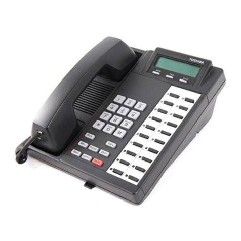
t\1KSU
TABLE
MOUNTING
MKSU
WALL
MOUNTING
MTOU
PCB
OPTIONS
PRINTED
CIRCUIT
BOARDS
MTOU
PCB
INSTALLATION
POWER
CONNECTIONS
PCB
INSTALLATION
CABLE
CONNECTIONS
MDF
CONFIGURATION
STATION
CABLE
CONNECTIONS
INTERCOM
CODE
ASSIGNMENTS
CO
LINE
CONNECTION
ELECTRONIC
KEY
TELEPHONE
GENERAL
. . . . . .
EKT
WALL
MOUNTING
CONVERTING
THE
EKT
SYSTEM
POWER-UP
INITIALIZE
SYST&W
TEST
PROCEDURES
EKT
FUNCTION
CHECK
FEATURE
CHECK
. . . . .
MISC.
EQUIPMENT
CONNECTION
WIRING
CONNECTION
MUSIC-ON-HOLD/BGM
SOURCE
MOH
VOLUME
CONTROL
...
EXTERNAL
PAGING
CONNECTION
DIRECT
EXTERNAL
SPEAKER CONNECTION
EXTERNAL
AMPLIFIER
CONNECTION
TALK-BACK
~WPLIFIER
BACKGROUND
MUSIC
(BGM)
VOLUME
SETTING
SEQUENCE
NIGHT
RELAY
SERVICE
..
-i -
i
i i
1
1
1
1
2
2
2
2
2
2
3
4
4
5
7
7
7
9
9
12
12
12
14
14
15
16
16
18
18
18
18
19
19
19
19
20
20
21
22
FIGURE
1
2
3
4
5
6
7
8
9
10
11
12
13
14
15
16
17
18
19
20
21
22
23
24
25
26
27
28
29
30
31
Strata
VI
SECTION 100-006-200
INSTALLATION INSTRUCTIONS
DECEMBER 1982
INSTALLATION INSTRUCTIONS
ILLUSTRATION
LIST
TITLE
PAGE
MCCU
and
CRDU
PCB
. . . . 1
MKSU
Wa
I l
Mounting
. . . . . 2
MKSU
Wa
11
Mounting
(Side
View)
3
MTOU
Relay
Layout
3
MTOU
Relay
Straps
. . . . . . 4
Impedance
Sw
i t
ch
(
SW2)
. . . 4
Key
Service
Uni t
(MKSU)
Internal
View
5
MKSU
Power
Connection
. . . 5
Mounting
CRDU
on
MCCU
. . . . 7
J.VK::CU/CRDU
Battery
Connections
7
System
Block
Diagram
. 8
MKSU
Cable
Connections
. . . . . . . 9
MKSU
Cable
Routing
. . . . . 9
MDF
Block
A
Connection
Diagram
.
10
MDF
Block
B
Connection
Diagram
11
CO/PBX
Modular
Wiring
Diagram
12
MKSU
Cable
Clamps
. . . .
12
Electronic
Key
Telephone
(EKT) . . .
13
Busy
Lamp
Field
(BLF)
EKT
13
20-Key
Executive
EKT
13
Removing
EKT
Base
14
Mounting
EKT
Base
. . .
14
EKT
Wiring
. . .
14
Mounting
Handset
Hanger
15
MCCU/CRDU
Battery
Connections
15
MTOU
Control
Switches
16
EKT
. . . . . . . . . .
17
MTOU
Wiring
Connections
19
MTOU
Relay
Connections
19
External
Amplifier
Connections
20
System
Volume
Controls
. . .
21
-
ii
-
01 GENERAL
01.01
This
section
describes
the
in-
stallation
procedures
necessary
to
en-
sure
proper
operation
of
the
STRATA
VI
system.
02
PACKING
02.01
When a STRATA
VI
system
is
received,
examine
all
packages
and
make
careful
note
of
any visible
damage.
If any
damage
is found, bring
it
to
the
attention
of
the
delivery
car-
rier
and make
the
proper
claims.
02.02
Check
the
STRATA
VI
system
against
the
purchase
order
and
packing
slip. If
it
is
determined
that
any
car-
tons
are
missing,
contact
your deli
very
carrier
immediately.
If
it
is
determined
that
any
equipment
within a
carton
is
missing,
contact
your
Toshiba
supplier
immediately.
02.03
After
unpacking
(before
in-
stallation
is
started),
inspect
all
equip-
ment for damage. If any damage is
detected,
contact
your
delivery
carrier
immediately. If possible,
retain
all
original
packing
material.
02.04
When
handling
(installing,
re-
moving, examining,
etc.)
a
printed
cir-
cuit
board,
do
not
touch
the
back
(soldered) side
or
the
edge
connector.
Always hold a PCB by
its
edge.
02.05
When
packing
or
storing
the
CRDU
and/or
MCCU,
ensure
the
fol-
lowing:
•
Do
not use
plastic
or any
type
of
conductive
material
for
packing
either
the
CRDU
or
the
MCCU.
• Use plain
paper.
NOTE:
Conductive
packing
material
may
cause
the
internal
back-
up
battery
to
discharge
and
damage
the
system.
SECTION 100-006-200
INSTALLATION INSTRUCTIONS
DECEMBER
1982
02.06
When.ever
storing
or
shipping
the
MCCU
and/or
CRDU,
always
ensure
that
the
battery
strap
is
in
the
OFF
position
(Figure
1).
SW!
BATTERY
STRAP
FIGURE l
NOTE:
Always
make
sure
the
battery
strap(s)
on
the
MCCU
and/or
CRDU
is
in
the
"ON"
position
just
prior
to
installation.
If
not,
the
SET
LED
on
the
MCCU
will
not
operate.
03
MKSU
LOCATION REQUIREMENTS
03.01
Power Requirements
03.02
The STRATA
VI
MKSU
re-
quires
24
VDC.
This
is
provided by
the
power supply, which
in
turn
requires
power from a grounded 115VAC
outlet.
The
outlet
should
be
separately
fused
and
rated
at
15
amps.
03.03
Two power supplies
are
available:
• MPSA-200
provides
sufficient
power
for
16
stations,
of
which a maxi-
mum
of
three
telephones
may
be
BLF EKTs.
-1 -
SECTION 100-006-200
INSTALLATION
INSTRUCTIONS
DECEMBER 1982
•
The
EPSA-104
is
necessary
if four
or
more BLF EKTs
are
required
within
a
system.
Up
to
16 BLF
EKTs may
be
installed
with
an
EPSA-104
power
supply.
03.04
The
54-inch
cord
provided
to
connect
the
power
supply
to
the
MKSU
dictates
the
relative
location
of
the
power
supply.
The
power
supply
is
also
equipped
with
a
10-ft.
AC
power
cord.
03.05
Optional
battery
back-up
units
(PBBU)
are
available
for
both
power
supplies.
The
PBBU
is a
printed
circuit
board
that
mounts
inside
the
power
supply
housing.
The
recommended
bat-
tery
pack,
which
is
customer
supplied,
consists
of
two
12VDC
batteries
(main-
tenance-free
automobile-type
is
recom-
mended). With
the
optional
battery
back-up
assembly
installed,
all
functions
of
the
STRATA
VI
system
will
operate
for
a
period
of
time
(which
is
in
direct
ratio
with
the
type
and
size
of
bat-
teries
selected)
after
a loss
of
normal
electrical
power.
No
calls
will
be
dis-
connected
during
switch-over
to
bat-
tery
power.
03.10
Ventilation
Requirements
03.11
Sufficient
ventilation
should
exist
to
allow
the
dissipation
of
heat
generated
by
the
power
supply
and
MKSU.
03.20
Environmental
Factors
03.21
Humidity
at
the
MKSU
loca-
tion
should
be
within
20
"'--'
80
%
(without
condensation),
and
the
temperature
should
be
relatively
constant
within
a
range
of
O""'-'
50°
C.
Exposure
to
dust
and
airborne
chemicals
should
also
be
taken
into
consideration.
03.30
Cabling
Considerations
03.31
The
MKSU
must
be
located
so
that
all
stations
are
within
1000
cable
feet
of
it.
Acceptable
cable
is
22
or
24
A
WG
inside
telephone
station
cable,
jacketed
but
not
shielded,
having
two
or more
wire
pairs.
04
MKSU MOUNTING
04.01 The
MKSU
is
designed
for
either
table
or wall
mounting,
but
comes
from
the
factory
configured
for
table
mounting.
For
wall
mounting
instructions,
ref
er
to
Paragraph
04.20.
04.10
Table
Mounting
the
MKSU
04.11
Since
the
MKSU
is
already
configured
for
table
mounting,
the
only
requirement
is
to
choose
a
suitable
loc-
ation
and
proceed
to
Section
100-006-
250, MPSA-200
Installation
or
Section
100-006-255,
EPSA-104
Installation.
04.20 Wall
Mounting
the
MKSU
04.21
Prepare
the
MKSU
for
wall
mounting
by
reversing
the
back
cover
to
expose
the
two
top
mounting
holes.
Proceed
as
follows:
•
Remove
and
save
the
five
screws
securing
the
back
cover.
•
Rotate
the
back
cover
180°,
and
realign
it
so
that
the
flanges
with
the
two
mounting
holes
project
above
the
top
of
the
MKSU,
as
shown in
Figure
2.
FIGURE 2
- 2 -
/
•
Reinstall
the
back
cover,
and
se-
cure
it
with
the
five
screws
that
were
removed
earlier.
04.22
Secure
the
MKSU,
as shown
in
Figures 2 and 3, with
fasteners
through
the
upper
two
holes and
the
single
lower
hole in
the
backplate.
The
fasteners
should
be
either
1/4-inch
molly
screws,
toggle bolts·, or lag
screws,
depending upon
the
type
of
wall
surface
being used.
WALL
CABLE
FIGURE 3
04.23
Prior
to
installing
any
printed
circuit
boards,
install
the
power supply
per
instructions
in
Section
100-006-250,
MPSA-200
Installation
or
Section
100-006-255, EPSA-104
Installation.
05
MTOU
PCB OPTIONS
05.01
The
MTOU
houses
several
options
that
must be
considered
before
it
is
installed
in
the
MKSU,
they
are:
• Background Music
Relay
Service--
the
optional
BR
relay
(Kl
socket,
Figure
4), if
installed,
provides a
dry
contact
at
the
BR
terminals
on
the
front
of
the
MTOU
to
control
cut-off
of
BGM
during an
external
page.
The
relay
operates
whenever
an
external
page
occurs.
-3 -
SECTION 100-006-200
INSTALLATION INSTRUCTIONS
DECEMBER 1982
• Night Relay
Service-the
optional
NR
relay
(K
2
socket),
if
installed,
provides a dry
contact
at
the
NR
terminals
on
the
front
of
the
MTOU. The
W3
strap
option
(Fig-
ure
4)
allows
the
relay
to
function
in
one
of
two modes.
a)
b)
FIGURE 4
Answering Machine
Control-
if
the
W3
strap
is
not
cut,
the
relay
is
operated
contin-
uously when
the
system
is
in
night
service.
This mode is
in
tended
for
indirect
control
of
an
answering
machine.
Night Bell
Control-if
the
W3
strap
is
cut,
the
relay
pulses
at
a
1-sec.
on,
3-sec.
off
rate
whenever
the
system
is
in
night
transfer
mode and an
incoming
call
is
ringing
the
system.
This mode
is
in-
tended
to
be used
for
indirect
control
of
an
external
night
bell.
•
External
Page
Impedance
Selec-
tion-the
external
page
output
appears
at
the
terminals
labeled
8/600 on
the
front
of
the
MTOU.
The
output
impedance
can
be
se-
lected
to
be
either
8 ohms or 600
ohms. If 8 ohms
is
selected,
the
output
will be via a
3-watt
SECTION 100-006-200
INSTALLATION
INSTRUCTIONS
DECEMBER 1982
amplifier
on
the
MTOU,
and
the
voice
path
will be
one
way.
If
600 ohms is
selected,
an
external
PA
amplifier
or
talk-back
amplifier
is
required
and
the
internal
voice
path
will
be
two
way.
05.02
To
equip
either
of
the
two
relay
service
functions;
obtain
the
op-
tional
relay
from
your
Toshiba
supplier
and
install
it
in
the
proper
location
on
the
!V!TOU,
per
Figure
5.
FIGURE
5
05.03
External
page
impedance
is
selected
with
the
SW
2
switch
located
adjacent
to
the
relay
sockets
on
the
!V!TOU
PCB
(Figure
6).
Decide
if
8-
or
600-ohm
impedance
is
required,
then
make
the
selection
by
positioning
the
SW2
switch
to
n3n or
11
600",
whichever
is
required.
Figure
6 shows
the
switch
in
the
8-ohm
position.
FIGURE
6
06 PRINTED
CIRCUIT
BOARDS
06.01 A maximum
of
seven
PCBs
They
can
be
installed
in
the
MKSU.
are:
NOTE:
For
proper
static
electri-
city
protection,
install
the
PCBs
in
the
Following
se-
quence.
•
MTOU
(Tone
Unit)-one
per
system.
• CRDU
(Repertory
Dial
Unit)--one
per
system,
to
be
installed
on
the
MCCU PCB when
the
Automatic
Dialing-Station
option
is
required.
• MCCU
(Central
Control
Unit)--one
per
system.
•
MSTU
(Station
Interface
Unit)-
install
one
for
each
group
of
eight
stations.
System
maximum is
two
(16
stations).
• MCOU
(Central
Office
Unit)-in-
stall
one
for
each
group
of
three
CO/PBX
lines.
System
maximum is
two
(six lines).
Two
types
of
MCOU
are
available.
a)
MF-to
be
used
when
DTMF
outpulsing
is
required.
b)
06.10
06.11
vi
des
24VDC
supply.
first.
DP-to
be
used
when
rotary
dial
outpulsing
is
required.
MTOU
PCB
Installation
The
MTOU
front
panel
pro-
the
connection
point
for
the
input
from
the
external
power
Therefore,
it
must
be
installed
06.12
Install
the
MTOU
PCB
in
the
MKSU
as
shown in
Figure
7.
- 4 -
0
0 MCOU
-Mf2
MTOU'l
[:
0
01
QEX.SP
02
02
QMOH
0
OJ
OJ
QBG"
0
C]n<T
~
HV
8'1100 °
BR 0
00
~R
EKT
K:'IU
0 0
~OK
0 0
LJ-~-LJ~
..
m-~u~-'°..r-io
00
0
SECTION 100-006-200
INSTALLATION
INSTRUCTIONS
DECEMBER 1982
06.22
Disconnnect
the
power
supply
from
the
115VAC
outlet.
Remove
the
plastic
protective
cover
from
the
power
terminal
strip
on
the
MTOU,
and,
with
the
supplied
cord,
connect
the
power
supply
to
the
terminal
strip
and
the
MKSU
frame
ground
(see
Figure
8) in
the
following manner.
White:
Black:
Green:
"24V"
"OV"
"FG" on
MKSU
"E" on power supply
Make
sure
the
wires
are
connected
to
matching
terminals
at
each
end.
co
1,2,3 10-17 Ext 18-25
FIGURE 7
Secure
the
power
cord
to
the
MKSU
with
the
plastic
cable
clamp
that
is
provided.
06.20
Power
Connection
06.21 Plug
the
power supply into a
115
VAC
outlet
and
check
its
output
voltage
to
be
sure
it
is
between
23.2
and
28.2VDC. If
the
voltage
is not
within
these
limits,
replace
the
power
supply
before
proceeding.
Q5ET
QMOH
0
Ow
Q!!GM
0
> ©
24V
DHT
, 0
8/600
J 0
80
00
""
E•T
•SU
J GREEN
0 0
MOH
-
-,,~
J
MCCU
"'TOU GREEN
CABLE CLAMP
06.23
Use
the
additional
green
wire
packed
with
the
system
to
bond
the
"E"
and
"OV"
terminals
on
the
power
supply
(see
Figure
8).
EPSA-104
POW
ER SUPPLY
GREEN
JUMPER
FIGURE 8
- 5 -
SECTION 100-006-200
INSTALLATION
INSTRUCTIONS
DECEMBER 1982
06.24
For
protection
against
static
electricity,
a
green
jumper
wire
is
attached
to
the
11
FG
11
screw
(refer
to
Figure
8). This
wire
must
be
connec-
ted
to
the
11
0V
11
terminal
on
the
MTOU
power
strip.
Reinstall
the
plastic
pro-
tective
cover
on
the
power
strip
at
this
time.
06.25
The
Toshiba
STRATA
VI
elec-
tronic
key
telephone
system
requires
a
solid
earth
ground
on
the
11
FG
11
terminal
on
the
MKSU
tray.
Failure
to
provide
such
a
ground
may
lead
to
confusing
trouble
symptoms
in
the
system
and,
in
extreme
cases,
circuit
board
failure.
e In most
installations,
within
the
continental
United
States,
the
ground
provided
by
the
11
third
wire
ground
11
at
the
commercial
power
outlet
will be
satisfactory
for
all
STRATA
VI
requirements.
llow-
ever,
in
a small
percentage
of
in-
stallations
this
ground
may
be
installed
incorrectly.
Therefore,
prior
to
installing
a
STRATA
VI
system,
the
third
wire
ground
must
be
tested
for
continuity
by
either
measuring
the
resistance
between
the
3rd
prong
terminal
(earth
ground)
and
a
metal
cold
water
pipe,
or
by using
11
commercially
available
emth
f~round
indicntor.
lf
neither
of
these
procedures
are
possible,
then
the
test
procedures
outlined
in
Parngrnph
06.26
should
be
performed.
CAUTION:
Hazardous
voltage
is
exposed
during
the
following
test.
Use
great
care
when
working
with
AC
powerline
voltage.
06.26
Test
Procedure
1.
Obtain
a
suitable
voltmeter
and
set
it
for
a
possible
reading
of
up
to
250VAC.
2.
Connect
the
meter
probes
between
- 6 -
the
two
main AC
voltage
points
on
the
wall
outlet.
The
reading
ob-
tained
should be
90"-'l30VAC.
3. Move
one
of
the
meter
probes
to
the
3rd
prong
terminal
(GND).
Either
the
same
reading
or
a
reading
of
0
volts
should be
ob-
tained.
4.
If
the
reading
is
OV,
leave
one
probe
on
the
GND
terminal
and
move
the
other
probe
to
the
2nd
voltage
terminal.
If
a
reading
of
OV
is
obtained
on
both
voltage
terminals,
the
outlet
is
not
pro-
perly
grounded.
Omit
Steps
5/'./
7,
and
proceed
directly
to
Step
8.
5. If a
reading
of
OV
on
one
terminal
and
a
reading
of
90
~
130VAC on
the
other
terminal
is
not
obtained,
the
outlet
is
not
properly
groun-
ded.
Omit
Steps
6
&:
7,
and
pro-
ceed
directly
to
Step
8.
6.
If
a
reading
of
OV
on
one
terminal
and
a
reading
of
90/\/130VAC
on
the
other
terminal
is
obtained,
re-
move
both
probes
from
the
outlet.
7.
Set
the
meter
on
the
noHMS/Rxir'
scale,
place
one
probe
on
the
G
ND
terminal
and
the
other
probe
on
the
terminal
which
gave
a
reading
of
OV.
A
reading
of
less
than
one
ohm should be
obtained.
If
a
reading
of
less
the
one
ohm
is
not
obtained,
the
outlet
is
not
ade-
quately
grounded.
8.
If
the
above
tests
show
that
the
outlet
is
not
properly
grounded,
that
condition
should
be
corrected
(per
Article
250
of
the
National
Electrical
Code)
by a
qualified
electrician
before
the
STRATA
VI
system
is
conn(~cted.
06.27
Ensure
that
the
power
switch
on
the
MTOU
is
OFF,
then
plug
the
power
supply
into
the
115VAC
outlet
and measure
the
voltage
at
the
MTOU
input
terminals.
Correct
any
problems
before
proceeding.
06.30 PCB
Installation
06.31
Mount
the
CRDU on
the
MCCU
if
required
(see
Figure
9).
P2~
·-
rn
f11
rTI
®
P3
~
rn rn
~
m
~
~
~
ii
mm
mma
rn
rnrn
rn
~
CRDU
Pl
.
FIGURE 9
06.32
Connect
the
memory
back-up
battery
on
the
MCCU
(and on
the
CRDU
if
the
system is
so
equipped).
Ref
er
to
Figure
10,
locate
the
SW
1
SW
3
Battery
Strap
CRDU
SWl
Battery
Strap
FIGURE
10
SECTION 100-006-200
INSTALLATION INSTRUCTIONS
DECEMBER 1982
battery
strap
on tl1e CH.DU, and
SW
3
battery
strap
on
the
MCCU;
plugs
are
shown
in
the
off
or
connected
position.
To
connect
battery,
remove
and
reinstall
strapping
plugs
so
that
they
bridge
center
pin
with
the
pin
labeled
ON.
the
the
dis-
each
the
the
06.33
Install
the
MCCU
in
the
cor-
rect
MKSU
position
(Figure
7).
06.34
Follow
the
position
arrange-.
ment
in
Figure
7, and
install
the
re-
quired
MSTU PCB(s).
•
#1
MSTU
serves
extensions
10..-v-17.
• #2 MSTU
serves
extensions
18
-'V"25.
06.35
Select
the
proper
type
of
MCOU
PCB
(MF
or
DP) and
install
the
required
number
in
the
position(s)
shown
in
Figure
7.
•
#1
MCOU
serves
CO
lines
1/\..-3.
• #2
MCOU
serves
CO
lines
4...-v6.
07 CABLE CONNECTIONS
07.01
Main
Distribution Frame
(MDF)
Configuration
07.02
Two
66MI-50
split
connection
blocks
(Figure
11)
are
recommended
as
the
fully-equipped
STRATA
VI main
dis-
tribution
frame
(MDF).
07
.03
A
25-pair
male-amphenol-
ended
cable
is
connected
directly
to
the
front
of
each
MSTU PCB and
fas-
tened
with
the
metal
bracket
that
is
provided
(Figure
12).
07
.04
Secure
the
cable(s)
to
the
bottom
of
the
MKSU
shelf
(Figure
12)
using
the
plastic
cable
clamp(s)
pro-
vided.
Route
the
cable(s) under
the
MKSU and
toward
the
rear,
as
shown
in
Figure
13.
07.05
Route
the
cable
from
#1
-7 -
SECTION 100-006-200
INSTALLATION INSTRUCTIONS
DECEMBER 1982
TO
CO/PBX
RJ-25C
2-PAIR
1
11=~~'~
1
[J
Q
mcri
:cc
..
~
~.2
CT]
[I
QI
c
~i
"\~,-·!·:"·
CTI
ret1
el
11
i:;];!IJG]
p-~.;r.;;.r
---:='~
EKT
MKSU
3-WIRE
CABLE
25-PAlR
CABLE
MDF:f.H
MDF:f2
10-17
18-25
2-PAIR
EKT
FIGURE
11
- 8 -

GREEN
JUMPER
WIRE
POWER
SUPPLY
FM
TUNER
EXTERNAL
SPEAKER
115VAC
2-PAIR
EKT
MSTU
(Ext.
10 17)
to
Block 1 and
the
cable
from
#2
MSTU
(Ext.
18
25)
to
Block
2.
'/
v/
Screws
Cable
Clamps
FIGURE
12
07
.06
Use
the
industry-standard
color
code
sequence
and
terminate
the
cables
from
the
MSTU
PCBs on
the
MDF
blocks as shown
in
Figures
14 and
15. (Use one
side
of
each
block for
each
cable.)
07.10
07.11
pair
WALL
CABLE
FIGURE
13
Station Cable Connections
Terminate
station
cables
the
individual
consecutively
2-

on
-9 -
SECTION 100-006-200
INSTALLATION INSTRUCTIONS
DECEMBER 1982
each
MDF
block;
attach
them
to
the
side
opposite
the
iV1STU
cable.
Use
bridging clips
to
connect
the
MSTU
cable
pairs
to
the
station
cable
pairs.
07
.12
The
cables
used for
station
wiring should be
industry-standard
quad
or
twisted
pair.
07
.13
The
overall
length
of
the
cable
run must
not
exceed
1000
ft.
for
24
AWG
wire.
WARNING:
When
installing
station
ca-
ble,
do
not
run
parallel
to
and
within
3
ft.
of
an
AC
power
line;
any
power
lines
should
be
crossed
at
right
angles
(90°)
only.
07.14
At
the
station
locations,
ter-
minate
the
station
cable
in
a
conven-
tional
4-
or
6-conductor
modular
station
connector
to
accommodate
the
modular
line
cord
from
the
EK
T.
The
standard
modular EKT
cord
length
is
7
ft.,
while
the
maximum allowed
length
is
25
ft.
07
.15
Figures
14 and
15
show
the
EKT wiring
arrangement.
07.16 The various
manufacturers
of
modular
station
blocks have employed
different
color
codes
to
indicate
the
sequence
of
pairs
in
their
blocks.
However,
the
color
code
most commonly
used
is
shown
in
Figures
14 and
15.
Verify
the
configuration
of
your modu-
lar
blocks
before
connecting
the
station
cables.
07
.20 Intercom Code Assignment
07
.21
Intercom
codes
are
assigned
permanently
to
specific
MSTU
cable
ap-
pearances
in
STRATA
VI.
Make
sure
the
station
cables
are
connected
to
the
proper
terminals
(Figures 14 and 15).
SECTION 100-006-200
INSTALLATION INSTRUCTIONS
DECEMBER 1982
TO
#1
MSTU
2-PAIR
JACKETED
STATION
CABLE
W-BL
..-~~~------
GN
BL·W
:-r--=~Rf-------------------------
WO
BK
OW
y
W-GN
GN·W
W·BR
BR·W
W-5
S·W
R·OL
BL·R
A·O
O·R
R·GN
GN·R
A·BA
BR·A
R·S
S·A
BK BL
BL-BK
BK·O
0-BK
BK·GN
GN·BK
BK·S
S-BK
Y·BL
BL·Y
y.o
O·Y
Y·GN
GN·Y
Y·BA
BR·Y
y.s
5.y
V·BL
BL-V
V·O
O·V
V-GN
GN·V
V·BR
BA·V
v.s
S·V
.--=-'--_i
__
Ext.
11
r-::-t--•
--
J
1
r:-:--.,__
____
_.
Ext.
12
J
_,----;-;-i._
__
.1
-
Ext.
13
-0
_J
-
''
l
-0
-
QD
Ext.
14
-
L..:.::'.....r---i>-J
= 1
!!liiW
0
Ext.
15
-J
MW0
1
-0
lll'lli!llll
Ext.
16
-J
=
QD
l
_.
Ext.
17
-J
DD
l
CJD
CJD
CJD
BRIDGING
CLIPS
CJD
CJD
CJD
CJD
CJD
CJD
CJD
G---
CJD
DD
CJD
DD
CJD
CJD
CJD
66Ml50
SPLIT
BLOCK
FIGURE
14
-
10
-
MODULAR
STATION
BLOCK
T2
I I I I I I
5 4 3 2
MODULAR
( )
C0 RD
-+--+---+-+-"
'
EKT
y
R2
......
Ext.
10
--
TO #2 MSTU
W-BL
qL·W
w.o
o.w
W-GN
GN·W
W·BR
BR·W
W·S
S-W
R·BL -
BL·R
-
R·O -
O·R -
R·GN -
GN·R -
-
R·BR
BR·R -
A·S -
S·R -
-
BK-BL -
BL·BK
BK·O -
0-BK
-
-
BK·GN
GN·BK
-
BK-BR -
BR-BK -
BK·S -
-
S-BK -
Y·BL -
BL·Y
y.o
O·Y
Y-GN
GN·Y
Y-BR
BA·Y
y.5
5.y
V-BL
BL·V
V·O
O·V
V-GN
GN·V
V-BR
BR·V
V·S
S·V
SECTION 100-006-200
INSTALLATION INSTRUCTIONS
DECEMBER 1982
2-PAIR
JACKETED
STATION
CABLE
GN
R
BK
y
l
~~
• _Ext. 19
J
l
Ext.
20
~-----'-
J
l
Ext.
21
J
17 l
Ext.
22
_J
l
Ext.
23
J
l
Ext.
24
J
l
Ext.
25
J
BRIDGING
CLIPS
NOT
USED
MODULAR
STATION
BLOCK
BK
T2
MODULAR
CORD
I I I I I
5 4 3 2
EKT
y
R2
Ext.
18
66Ml50
SPLIT
BLOCK
FIGURE 15
-11 -
SECTION 100-006-200
INSTALLATION
INSTRUCTIONS
DECEMBER 1982
NOTE:
White
and
blue
(T3 & R3)
are
not
used
for
STRATA
VI
sta-
tion
line
connectors.
07
.30
CO
Line
Connection
07
.31
The
CO/PBX
lines
are
intro-
duced
into
the
STRATA
VI
system
via
6-wire
modular
line
cords
(no
longer
than
25
ft.)
connected
directly
to
a
jack
on
the
MCOU
PCB.
Each
modular
cord
contains
three
lines.
The
opposite
end
of
each
cord
then
terminates
directly
into
an
RJ-25C
jack
provided
by
the
telephone
company
(Figure
16).
TO
CO/PBX
w
t:C
z
st
r~
u w
E-<
<C
0 w
...:i
::::i
.......
0.::
::r::
...:i
w w
...:i
3:
co
0:::
v
~
co
:--
--
----
--,-
-,-
-,-:
6-POSITION
I I PLUG
L--
-
--
-
----
.J
T3
T2
Rl
Tl
R2
R3
' /
TO MCOU PCB
FIGURE
16
• #1 MCOU
serves
CO
lines
1
..-v3.
• #2
IVICOU
serves
CO
lines 4
rv6.
07
.32
Secure
the
modular
cords
to
the
MKSU
shelf
(Figure
17) using
the
·
plastic
cable
clamps
that
are
provided.
FIGURE
17
08 ELECTRONIC KEY TELEPHONE
INFORMATION
08.01
General
08.02
All
STRATA
VI
EKTs may
be
used
as desk
units
or
wall-mounted
telephones.
Each
one
measures:
Width
Depth
Height
8.8
inches
(224
mm)
9.1
inches
(230
mm)
4.0
inches
(102
mm)
and
is
equipped
with
14
line
and
f
ea-
ture
keys in
addition
to
its
push-button
dial
pad.
Six
of
the
keys
are
utilized
for
central
office/PBX
lines,
two
for
intercom
lines
and
the
remaining
six
keys
are
used
for
feature
operation
(Figure
18).
08.03
Each
EKT f
ea
tu
res
a
modular
handset
cord
and
is
connected
to
the
system
via a
4-conductor
modular
line
cord.
08.04
An
optional
Busy Lamp
Field
(BLF) EKT
(Figure
19)
provides
LED
indication
on
which
stations
are
in
use.
08.05
The
20-key
EKT
(Figure
20)
-
12
-
Modular
Cord
Speaker
Volume-Ring
Tone
&
Intercom
Voice
Dial
Pad
t
[J[ffi][]J
mm
ffi1
~[]]ru]
GmGJ
FIGURE
18
FIGURE 19
-13 -
Key
SECTION 100-006-200
INSTALLATION INSTRUCTIONS
DECEMBER 1982
Speaker
Volume-Dial
Tone
&
Voice
Level
Flash
& Message
CJ1L
Waiting
Key
0
Do
Not
Disturb
f
Key
CJ
..........
_
Outside
Line
Access
Keys
FIGURE 20
SECTION 100-006-200
INSTALLATION INSTRUCTIONS
DECEMBER 1982
has
the
same
overall
dimensions
as
the
standard
EKT,
and
is
installed
in
exactly
the
same
manner.
See
Program
5XX in
Section
100-006-300,
Program-
ming,
for
inputting
information
con-
cerning
the
20-key.
It
is
equipped
with
10
additional
feature
keys-see
Section
100-006-100,
General
Description,
for
additional
information.
08.10
EKT Wall Mounting
08.11
An
optional
handset
hanger
kit
is
required
to
convert
either
type
of
EKT
for
wall
mounting.
The
EKT
may
be
mounted
on a
wall
or
any
other
flat,
vertical
surf
ace
to
which
the
base
can
be
secured.
08.12
When
selecting
the
mounting
site,
consider
the
EKT
weight
and
the
additional
stresses
to
which
the
mounting
will
be
subjected.
08.13
Mounting
screws
or
mollies,
appropriate
for
the
surf
ace
on
which
the
telephone
is
to
he
secured,
must
be
provided
by
the
installer.
08.14
Locking
tabs
secure
the
base
to
the
EKT.
The
direction
in
which
the
base
is
attached
to
the
EK
T
de-
termines
whether
it
will be
used
as
a
desk
unit
or
wall
unit
(it
is
factory-
configured
as
a
desk
unit).
Disengage
the
locking
tabs
by
pushing
downward
on
the
base
(Figure
21).
FIGURE
21
08.15
Refer
to
Figure
22,
choose
which
of
the
choices
are
appropriate
for
the
tail
cord
route,
and
then
cut
them.
FIGURE 22
08.16
Secure
the
base
to
the
de-
sired
wall
site.
Use a
spirit
level
and
make
certain
the
top
of
the
base
is
level
and
that
the
deeper
portion
is
down.
08.17
Route
the
tail
cord
through
the
holes
in
the
base
and
secure
the
EKT
(Figure
23).
Test
the
sturdiness
of
the
EKT
mounting.
FIGURE 23
08.20
Converting
the
EKT
08.21
Refer
to
Figure
24,
the
op-
-14 -
tional
handset
hanger
kit
(available
from your Toshiba supplier) must
be
used
whenever
the
EKT is
wall-mounted.
Handset
Hanger
Nurnber
Card
Card
Cover
FIGURE
24
08.22
Remove
the
card
cover
by
in-
serting
a
paper
clip
in
the
hole
at
one
end. Bend
the
cover
up and remove
it
and
the
number
card.
08.23
Install
the
handset
hanger
in
to
place
and
tighten
the
self-tapping
screws.
Reinstall
the
number
card
and
card
cover
and
connect
the
modular
plug
to
the
modular
jack.
09
SYSTEM POWER-UP INITIALIZE
09.01
The STRATA
VI
has a
list
of
standard
system
data
assignments
stored
in
ROM
that
can
be
entered
at
any
time
by
performing
the
initialize
sequence
outlined
below. The
system
must be
initialized
when
it
is
first
installed
or
whenever
the
MCCU PCB
is
changed.
This will allow
the
system
to
be
tested
and any
faults
to
be
corrected
before
time
is
spent
on
programming.
SECTION 100-006-200
INSTALLATION INSTRUCTIONS
DECEMBER
1982
NOTE:
Do
not
initialize
if
using
a
pre-programmed,
battery-pro-
tected
HCCU.
09.02
Ref
er
to
Figure
25
and
verify
that
the
battery
on
the
MCCU
(and
CRDU, if equipped)
is
connected
to
ensure
that
data
changes
entered
after
initialization
will
not
be
lost
due
to
power
failure.
NOTE:
The
SET
LED
will
not
func-
tion
if
the
MCCU
battery
is
not
connected.
Sl'.3
BATTERY
STR,\P
SW!
BATTERY
STRAP
FIGURE 25
09.03
To
initialize
the
system
data
memory,
ref
er
to
Figure
26
and perform
the
following
steps:
a)
Place
the
power
switch
on
the
MTOU
PCB
in
the
ON
position.
b)
Depress
the
INT
switch
on
the
MCCU, and hold
it
in.
c) Depress
the
SET
switch
and allow
it
to
lock.
-15 -
SECTION 100-006-200
INSTALLATION
INSTRUCTIONS
DECEMBER 1982
0 "4COlJ
-Mrt
01
Ot
01
Oi
O•
FIGURE
26
d)
Depress
and
release
the
SET
switch
again.
e)
Release
the
INT
switch.
f)
Cycle
the
MTOU
power
switch
OFF
and
ON.
09.10
The
Automatic
Dialing memory
will conti:l.in
random
numbers
when
the
system
is
powered
up
initially.
To
clear
the
memory;
therefore
preventing
meaningless
numbers
from
being
dialed,
proceed
as
follows:
a) To
clear
Automatic
Dial-System
memory
(24
numbers):
e Lock in
the
SET
switch
on
the
MCCU-the
MCCU
LED
and
the
MW/FL LED on
Ext.
17
will
be
on.
e
Operate
the
LS1'K.RJ
key on
Ext.
17-SPKR
LED
will be on
steadily.
c Dial
00
0 0 on
the
dial
pad-the
SPKR
LED
will
flash
continuously.
(')
Operate
the
following
keys:
0
0
aNlJl lCID
&:IT:J
~-the
responding
LEDs will
steadily.
cor-
light
e
Operate
the
IHOLDI
key-all
Ext.
17 LEDs
(except
MW
/FL)
will
go
off.
•
Release
the
SET
switch
on
the
MCCU-the
MCCU
LED
and
the
MW/FL
LED
on
Ext.
17 will
go
off.
b) To
clear
the
optional
Automatic
Dial-Station
memory:
e Lock in
the
SET
switch
on
the
MCCU-the
MCCU
LED
and
the
MW
/FL
LED
on
Ext.
17
will
go
on.
•
Operate
the
ISPKR I key on
Ext.
17-the
SPKR
LED
will
be
on
steadily.
• Dial 0 0
Won
the
dial
pad-
SPKR
LED will
flash
continu-
ously.
•
Operate
the
following
keys:
lffIT2
fCQ2l
~
~the
cor-
responding
LEDs will
light.
•
Operate
the
IHOLDI
key-all
Ext.
17 LEDs
(except
MW
/FL)
will
go
off.
•
Release
the
SET
switch
on
the
lVlCCU-the
MCCU
LED
and
the
MW
/FL
LED
on
Ext.
17
will
go
off.
09.11
If
the
appropriate
preceeding
sequence
fails,
refer
to
Section
100-
006-500,
Fault
Finding
Procedures,
for
assistance
in
locating
the
fault.
10 SYSTEM TEST
PROCEDURES
10.01
EKT
Functional
Check
10.02
Verify
the
basic
system
func-
-
16
-
tions
and
confirm
the
proper
func-
tioning
of
the
EKT
itself.
Refer
to
Figure
27,
and
perform
the
following
test
procedure
at
each
station.
Begin
with
Ext.
10.
)1ra
....,.,..
-:ootlllOl.ll!
c:::J
c::J
CJ
CJ
FIGURE
27
10.03
With
handset
on-hook:
•
Operate
[]!IT]]
key
INT 1 LED:
I-use
flash
SPKR
LED: on
steady
Listen
for
INT
dial
tone
via
EKT
speaker
•
Adjust
speaker
volume
with
the
volume
control
on
the
rear
right
side
of
the
EKT.
•
Operate
INI2
key
INT
2 LED:
I-use
flash
SPKR
LED: on
steady
Listen
for
INT
dial
tone
via
EKT
speaker
•
Operate
~
key
CO 1 LED:
I-use
flash
SPKR
LED: on
steady
Listen
for
CO/PBX
dial
tone
via
EKT
speaker
• Dial any
digit
(2
-
9)
on
the
dial
pad
and
dial
tone
will
stop.
-
17
-
SECTION 100-006-200
INSTALLATION INSTRUCTIONS
DECEMBER 1982
e
Operate
[MW/FL
I key
Listen
for
circuit
break
fol-
lowed by
dial
tone
after
ap-
proximately
2
seconds.
•
Operate
fCT[2l
key
CO 1 LED:
I-use
flash
SPKR
LED: on
steady
Listen
for
CO/PBX
dial
tone
via
EKT
speaker
NOTE:
If
no
CO
/PBX
facility
is
con-
nected
to
a
CO
key,
dial
tone
will
not
be
heard
but
the
LED
is
still
functional.
•
Operate
ICIT]l key
CO 3 LED:
I-use
flash
SPKR
LED: on
steady
Listen
for
CO/PBX
dial
tone
via EKT
speaker
•
Operate
~
key
CO 4 LED:
I-use
flash
SPK R LED: on
steady
Listen
for
CO/PBX
dial
tone
via
EKT
speak
er
•
Operate
~
key
CO 5 LED:
I-use
flash
SPKR
LED: on
steady
Listen
for
CO/PBX
dial
tone
via EKT
speaker
•
Operate
~
key
CO 6 LED:
I-use
flash
SPK R LED: on
steady
Listen
for
CO/PBX
dial
tone
via EKT
speaker
•
Operate
ISPKR
I
key
SPKR
LED:
off
EKT
speaker:
off
•
Operate
ON:Q
key
DNO
LEO: on
•
Operate
c:ND
key
DND
LED:
off

Other manuals for Strata VI

3

Other Toshiba Telephone System manuals

Toshiba Strata DK8 Manual

Toshiba

Toshiba Strata DK8 Manual

Toshiba Strata S Manual

Toshiba

Toshiba Strata S Manual

Toshiba Strata CTX User manual

Toshiba

Toshiba Strata CTX User manual

Toshiba Strata DK14 Service manual

Toshiba

Toshiba Strata DK14 Service manual

Toshiba Strata CTX User manual

Toshiba

Toshiba Strata CTX User manual

Toshiba Strata DK8 Operating and maintenance instructions

Toshiba

Toshiba Strata DK8 Operating and maintenance instructions

Toshiba Strata VI User manual

Toshiba

Toshiba Strata VI User manual

Toshiba Strata CTX670 User manual

Toshiba

Toshiba Strata CTX670 User manual

Toshiba Strata VI Series User manual

Toshiba

Toshiba Strata VI Series User manual

Toshiba Strata CIX LUCA User manual

Toshiba

Toshiba Strata CIX LUCA User manual

Toshiba Strata AirLink DK40 Owner's manual

Toshiba

Toshiba Strata AirLink DK40 Owner's manual

Toshiba Strata CTX100 Operating and maintenance instructions

Toshiba

Toshiba Strata CTX100 Operating and maintenance instructions

Toshiba Strata DK 2000-series User manual

Toshiba

Toshiba Strata DK 2000-series User manual

Toshiba Strata CTX User manual

Toshiba

Toshiba Strata CTX User manual

Toshiba Strara CTX Series Manual

Toshiba

Toshiba Strara CTX Series Manual

Toshiba Strata DK14 Manual

Toshiba

Toshiba Strata DK14 Manual

Toshiba Strata AirLink DK424 Quick start guide

Toshiba

Toshiba Strata AirLink DK424 Quick start guide

Toshiba Strata CIX40 Manual

Toshiba

Toshiba Strata CIX40 Manual

Toshiba Strata DK14 Operating and maintenance instructions

Toshiba

Toshiba Strata DK14 Operating and maintenance instructions

Toshiba Strata CIX LVMU Installation guide

Toshiba

Toshiba Strata CIX LVMU Installation guide

Toshiba Strata AirLink DK16 Manual

Toshiba

Toshiba Strata AirLink DK16 Manual

Toshiba Strata CTX Attendant Console User manual

Toshiba

Toshiba Strata CTX Attendant Console User manual

Toshiba Strata DK14 Manual

Toshiba

Toshiba Strata DK14 Manual

Toshiba Strata CTX Owner's manual

Toshiba

Toshiba Strata CTX Owner's manual

Popular Telephone System manuals by other brands

Aristel DV-22 installation manual

Aristel

Aristel DV-22 installation manual

Nortel BCM50 2.0 installation guide

Nortel

Nortel BCM50 2.0 installation guide

Panasonic KX-TD500CE Programming guide

Panasonic

Panasonic KX-TD500CE Programming guide

Nortel Norstar SMDR6 installation guide

Nortel

Nortel Norstar SMDR6 installation guide

Alcatel OmniPCX 4400 user guide

Alcatel

Alcatel OmniPCX 4400 user guide

Panasonic KX-TS108W operating instructions

Panasonic

Panasonic KX-TS108W operating instructions

Panasonic KX-TSC14W - KX TSC14 Corded Phone operating instructions

Panasonic

Panasonic KX-TSC14W - KX TSC14 Corded Phone operating instructions

GE 25982EE1 user guide

GE

GE 25982EE1 user guide

Avaya BM12 user guide

Avaya

Avaya BM12 user guide

HYBREX GDS-1280N installation manual

HYBREX

HYBREX GDS-1280N installation manual

Panasonic KX-TD612CE installation manual

Panasonic

Panasonic KX-TD612CE installation manual

Panasonic KX-TA624 manual

Panasonic

Panasonic KX-TA624 manual

Bell System 2960A01M Installation, operation and maintenance instructions

Bell System

Bell System 2960A01M Installation, operation and maintenance instructions

Black Box Video Sentry Color Tilt Phone System brochure

Black Box

Black Box Video Sentry Color Tilt Phone System brochure

Radio Shack Automatic Desktop Dialer user manual

Radio Shack

Radio Shack Automatic Desktop Dialer user manual

Panasonic EASA-PHONE KX-T123210 installation manual

Panasonic

Panasonic EASA-PHONE KX-T123210 installation manual

Panasonic KX-TVS50 - 2 Port Voicemail System installation manual

Panasonic

Panasonic KX-TVS50 - 2 Port Voicemail System installation manual

Samsung iDCS 500 Administration guide

Samsung

Samsung iDCS 500 Administration guide

manuals.online logo
manuals.online logoBrands
  • About & Mission
  • Contact us
  • Privacy Policy
  • Terms and Conditions

Copyright 2025 Manuals.Online. All Rights Reserved.