manuals.online logo
Brands
  1. Home
  2. •
  3. Brands
  4. •
  5. ClearCube
  6. •
  7. Chassis
  8. •
  9. ClearCube A3000 User manual

ClearCube A3000 User manual

Quick Start Guide
ClearCube Technology 8834 Capital of Texas Hwy N Austin, Texas 78759 voice 512 652 3500 www.clearcube.com
A3000_QSG_rev_e.fm — Enter your TB topic here
The ClearCube A3000 chassis is a centralized 6U-form factor chassis
that houses as many as ten A Series blades. A standard 42U 19-inch
rack can hold as many as seven A3000 chassis, for a total of 70 blades.
Each A3000 chassis is a self-contained unit providing all of the Ethernet
and power connections that the PC blades need.
INSTALLING THE A3000 CHASSIS
The A3000 chassis is shipped with four rack-mount brackets that allow
universal mounting in standard 19-inch racks or cabinets. Inspect your
installation to determine the best method and mounting points for these
brackets. When installing an A3000 chassis, be sure to follow the rack
or cabinet vendor’s installation guidelines.
CAUTION: Never install the A3000 chassis in a two-post rack.
The A3000 chassis draws cool air in through the front of the chassis,
and exhausts it out the back. If you plan to use a cabinet enclosure,
ensure that you have at least 34 inches (86cm) of interior depth mea-
sured from the front of the unit, to accommodate the cabling and air flow
that exits from the rear of each chassis. The spacing between the front
and back rails can be no more than 30 inches (76cm).
The ClearCube standard Chassis Accessory Kit fits all standard 19”
racks and provides a set of front and back mounting brackets, with the
necessary hardware. The optional ClearCube Chassis Rapid-Mount
(CRM) kit is specially designed to fit ClearCube-supplied cabinets and
racks that feature four posts with square mounting holes for snap-in
rack nuts. While this is an industry-standard style for mounting hard-
ware, not all third-party racks can accept the CRM kit.
The A3000 chassis is designed to be stacked in a rack with each chas-
sis helping to support the one above to evenly distribute the weight of
the blades. When an A3000 chassis is the bottom chassis in a rack, or
when there is open space below an A3000 chassis, a reinforcing rack
brace should be used on the front of the chassis.
Attach the rack brace to the bottom of any chassis that does not have
equipment installed in the rack space immediately below. Do the following:
1. Slip the rack brace flanges onto the chassis behind the rack ears, as
shown in the diagram to the left.
2. Secure the brace to the chassis with the two included 8-32 pan head
screws passing through the brace.
After installing the A3000 chassis, attach the grounding strap to the
ground point on the right-hand side of the AC Tray on the A3000 chas-
sis and to the rack or cabinet in which the A3000 chassis is installed.
Ensure that the rack or chassis is properly grounded. See diagram on
the next page.
CAUTION: Never lift the A3000 chassis with blades installed.
The A3000 chassis has two power receptacles, one for each half of the
chassis. When only one power cord is connected to the A3000 chassis,
only the side of the chassis that is connected to power will supply power
to the blades. Use both the AC power cords packaged and supplied with
the chassis.
A3000
Chassis
Attach rack brace to the bottom
chassis in the rack or cabinet.

ClearCube Technology 8834 Capital of Texas Hwy N Austin, Texas 78759 voice 512 652 3500 www.clearcube.com
G020079-E rev 10/17/2006
INSTALLING BLADES
A Series blades need to be pre-configured before installing them in the
chassis. You need a VGA monitor with a DB-15 mini connector, a keyboard,
and a mouse. The keyboard and mouse can be USB or PS/2. An IEC power
cord is also required. For more information, please see the A Series Data
Center Products User’s Guide or the A1010 Quick Start Guide.
To install an A Series blade in the A3000 chassis, do the following:
1. Remove the front bezel on the chassis by pressing the latch on the
right side of the chassis toward the left of the chassis.
2. Tilt the bezel forward, and lift it free from the chassis.
3.
Orient each PC blade right-side up, with the D-shaped cutout in the front
panel on top, then slowly insert the PC blade into the chassis by lining up
the PC blade edges with both the top and bottom guides in the chassis.
4. Slots are numbered from 1 to 10, starting with the left-most slot. There
will be a slight resistance to insertion when the rear connector goes into
the backplane power connector. When properly seated, the PC blade is
flush with the front edge of the bottom guide bracket.
5. After inserting all the blades, replace the bezel.
6. Attach an ethernet cable to each blade. The ethernet cable engages a
latch that secures the blade inside the A3000 chassis.
7. Press the power button (the top button) to turn on each blade. When
you insert the PC blade, the power does NOT turn on automatically. You
must depress the power button on the back of the blade to power it on.
To remove a blade, do the following:
1. Remove the front bezel on the chassis by pressing the latch on the
right side of the chassis toward the left of the chassis.
2.
Power down the blade using the power switch on the back of the blade.
3.
Remove the ethernet cable from the blade. If necessary, push up gen-
tly on the latch on the ethernet jack.
4. Pull gently on the blade until it slides out. Use the D-shaped cutout on
the front panel as a handle. Be sure to support both ends of the blade
when you remove it completely from the chassis.
For more information, please contact ClearCube Technical Support.
Email: support@clearcube.com
Website: support.clearcube.com
In the US (866) 652-3400
Outside the US +1 (512) 652-3400
WEEE Initiative Notice
This electronic product is recyclable under
WEEE (Waste Electrical and Electronic
Equipment) guidelines and should not
be discarded as regular trash.
Please locate your nearest recycling facility
to ensure proper disposal of this product,
or contact ClearCube Technology
on the web at:
http://support.clearcube.com/
or by email at:
recycle@clearcube.com
for more information.
Ground Strap
Ground Strap
(attach to rack frame)
(attach with 10-32 screw)
CAUTION:
High Leakage Current
Connect chassis earth ground
before supplying AC power
to chassis.

Other manuals for A3000

1

Other ClearCube Chassis manuals

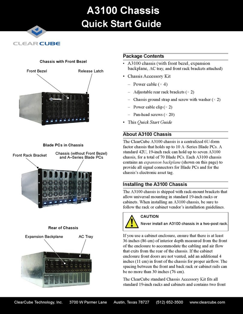
ClearCube A3100 User manual

ClearCube

ClearCube A3100 User manual

ClearCube R4300 Mounting instructions

ClearCube

ClearCube R4300 Mounting instructions

ClearCube V7000 User manual

ClearCube

ClearCube V7000 User manual

ClearCube A3000 User manual

ClearCube

ClearCube A3000 User manual

ClearCube A Series Operating and safety instructions

ClearCube

ClearCube A Series Operating and safety instructions

Popular Chassis manuals by other brands

DEV 1953 user manual

DEV

DEV 1953 user manual

Sun Microsystems Sun Fire B1600 Administration installation guide

Sun Microsystems

Sun Microsystems Sun Fire B1600 Administration installation guide

Advantech AIMB-B1000 Series user manual

Advantech

Advantech AIMB-B1000 Series user manual

Pickering 40-914 user manual

Pickering

Pickering 40-914 user manual

IBM E Product guide

IBM

IBM E Product guide

HP Moonshot 1500 Setup and installation guide

HP

HP Moonshot 1500 Setup and installation guide

Supero SC823i user guide

Supero

Supero SC823i user guide

Hisense MSD6586 Service manual

Hisense

Hisense MSD6586 Service manual

Advantech ACP-1320BP user manual

Advantech

Advantech ACP-1320BP user manual

Cisco ONS 15454 manual

Cisco

Cisco ONS 15454 manual

Memotec NetPerformer SDM-9600 Hardware installation guide

Memotec

Memotec NetPerformer SDM-9600 Hardware installation guide

National Instruments PXI Express PXIe-1071 user manual

National Instruments

National Instruments PXI Express PXIe-1071 user manual

Optical Systems Design OSD350B Operation manual

Optical Systems Design

Optical Systems Design OSD350B Operation manual

National Instruments PXI NI PXI-1052 user manual

National Instruments

National Instruments PXI NI PXI-1052 user manual

Spirent communications SmartBits 200 Replacement

Spirent communications

Spirent communications SmartBits 200 Replacement

SilverStone SUGO 16 manual

SilverStone

SilverStone SUGO 16 manual

Advantech AIMB-C200 user manual

Advantech

Advantech AIMB-C200 user manual

Optimus DA-4PM/0F2 operating instructions

Optimus

Optimus DA-4PM/0F2 operating instructions

manuals.online logo
manuals.online logoBrands
  • About & Mission
  • Contact us
  • Privacy Policy
  • Terms and Conditions

Copyright 2025 Manuals.Online. All Rights Reserved.