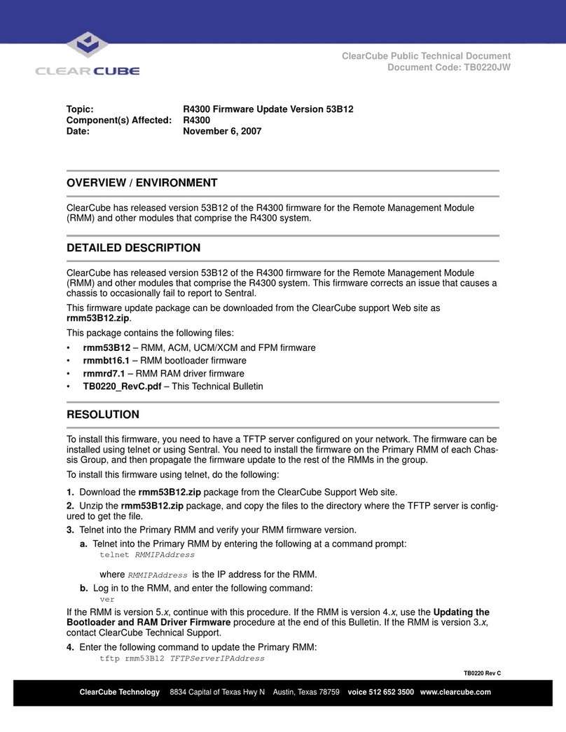
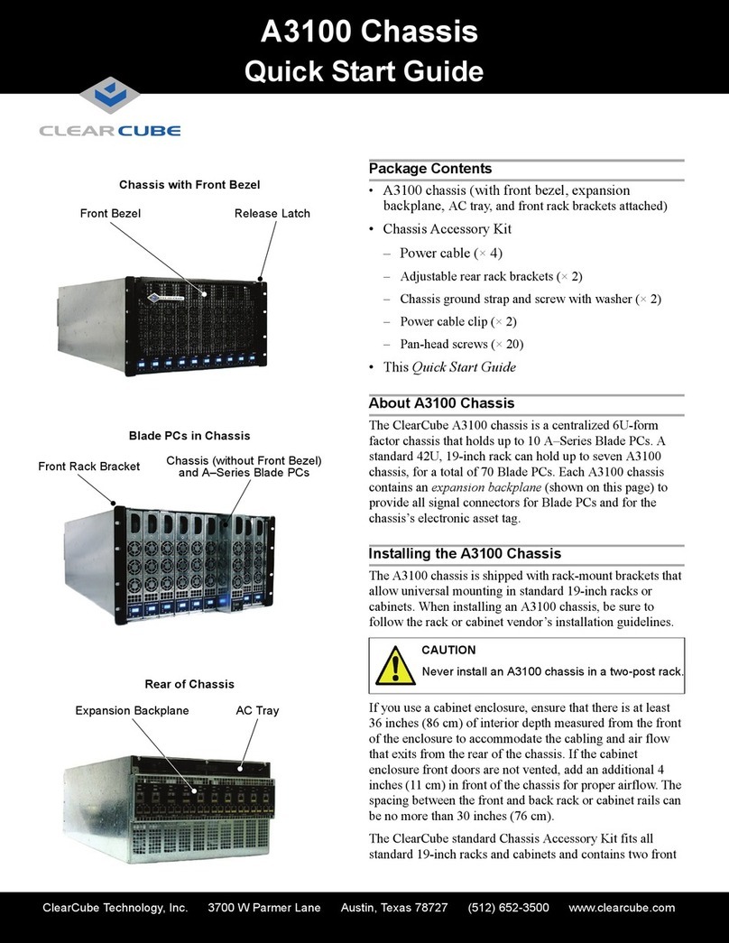
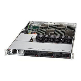
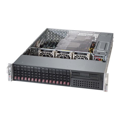
ClearCube V7000 User manual

s
ClearView IPMI 1.0
User’s Guide
for V7000 Chassis and
V7100S Blade Management
ClearCube Technology, Inc.

Copyright©2008 ClearCube Technology, Inc. All rights reserved.
Under copyright laws, this publication may not be reproduced or transmitted in any form, electronic or mechanical,
including photocopying, recording, storing in an information retrieval system, or translating, in whole or in part,
without the prior written consent of ClearCube Technology, Inc.
This information is subject to change without notice and ClearCube shall not be liable for any direct, indirect,
special, incidental or consequential damages in connection with the use of this material.
Trademarks
Sentral™, ClearCube™, C3 Architecture™, Blade Switching BackPack™, PC Blade™, and C/Port™
are trademarks of ClearCube Technology Inc. Product and company names mentioned herein
are trademarks or trade names of their respective companies.
Patents
The ClearCube Architecture and its components described in this user manual
are protected by numerous granted and pending U.S. and international patents.
Granted patents include: US05926172, US05966056, US05994952, US06012101, US06020839, US06037884,
US06038616, US06119146, US06148182, US06167241, US06385666, US06421393, US06426970,
US06633934, US06708247, US06735658, US06886055, and US06944826.
Inquiries regarding patented technology should be directed to
ClearCube Corporate Headquarters.

iii
Table of Contents
1. Overview ..................................................................................................1
2. Login and Blade System.........................................................................2
2.1. Blade System View.............................................................................5
2.2. Blade UI..............................................................................................8
2.3. Power Supply UI...............................................................................10
2.4. Gigabit Switch UI..............................................................................12
2.5. CMM UI ............................................................................................16
2.6. InfiniBand UI.....................................................................................19
2.7. Failure Summary UI..........................................................................21
2.8. Blade Summary UI ...........................................................................21
2.9. Power Supply Summary UI ..............................................................22
2.10. Gigabit Switch Summary UI..............................................................23
3. Text Console..........................................................................................24
4. KVM Console and Optimizing Keyboard and Mouse Settings..........26
5. Event Log...............................................................................................28
6. Logon Management ..............................................................................29
7. Virtual Media..........................................................................................32
8. CMM Setting...........................................................................................33
9. Connecting to the Slave CMM..............................................................34

1
1. Overview
You can use ClearCube ClearView IPMI to manage ClearCube V7000 chassis
containing one or more Chassis Management Modules (CMM) and ClearCube
V7100S blades. ClearView IPMI sends messages to and from the CMM. Messages
are encapsulated in an RMCP+ (Remote Management Control Protocol) packet that
follows the IPMI standard.
ClearView IPMI monitors and reports on the status of a V7100 system, including the
blade server, power supply, gigabit switch, InfiniBand and CMM modules. ClearView
IPMI shows the V7000 and V7100 in a GUI for easy management, enabling
administrators to monitor the status of each blade module. ClearView IPMI also
supports remote KVM and virtual media. This document describes how to use
ClearView IPMI to manage V7000 and V7100 systems.

2
2. Login and Blade System
One V7000 chassis can have a maximum of two CMM modules, with one as the
master CMM and the other one as the slave CMM. Only the master CMM has the full
management functions for the V7000 chassis. For normal system management, you
should connect to the master CMM. The slave CMM is also operating when the
V7000 is turned on. It will take the role of master CMM if the original master CMM
is reset or hangs. By the way, once slave CMM take over master, the master CMM
will become the slave CMM.
In the ClearView IPMI device list, as shown in Figure 1-2, you will see the V7000
icon ( ) once the CMM added. Double-click this item to display the login screen. To
login:
1. Type in your Username in the Login ID box.
2. Type in your Password in the Password box and click on Login.
3. The default username and the default password are both ADMIN.
Figure 1-2. Logging on to the V7000

3
Once you login successfully, the Blade System tab is displayed. This is the main
system management UI (User Interface), as shown in Figure 1-3.
Figure 1-3. Blade System UI (User Interface)
The upper window displays the status of all blades being monitored. Any changes to
the V7100S will be reflected in this view. For example, if someone removes blade
module 1, you will see the blade 1 icon disappear (become grayed out). If you turn off
blade module 10, the power LED on blade 10 will become amber. Different types of
blade modules can occupy the same blade system. If you install a different type of
blade module, its icon in the Blade System View will likewise appear slightly
different due to its type. In this way, the Blade System View reflects a real and current
picture of the V7100S modules.
Each module icon in the Blade System View can be clicked on to show a detailed list
of functions in the bottom (Module User Interface) window. Additional summary
items can be viewed as here well. The Module UI allows users to obtain additional
information and send additional commands to the blade modules.
The Module UI has a detach button ( ) at the upper-right of the window. Clicking
on it will detach the UI as a single window as shown in Figure 1-4. This is useful for
continual monitoring of a specific blade module.
Blade System View
Module UI

4
Figure 1-4. Detached Module UI Window

5
1.1. Blade System View
Figure 2-1. Blade System View
As shown in Figure 2-1, the Blade System View provides an overview of the V7000
and V7100S system.
There are four sections in the Blade System View:
Summary: Shows a summary of failures and how many of each type of module
have been installed. The Failure, Blade, Power and Switch items are shown in
greater detail in the Module UI.
Blade System: As shown in Figure 2-2, the Blade System View shows both front
and rear views of the blade system. The front view shows blade module status
while the rear view shows the status of the power supply, gigabit switch,
InfiniBand and CMM. A yellow rectangle appears around an icon when it is
selected (clicked on), as shown in Figure 2-3. Each icon has a symbol to show its
current status. Each module may display one or more symbols. Refer to the
Legend Help (Figure 2-4) to determine the meaning of a symbol. (Click Legend
Help in the View Option window at the lower right area of the screen.)
Figure 2-2. Blade Module Layout
Blade Modules
Gigabit Switch
InfiniBand
(Or CMM)
Power Supply
Modules
CMM

6
Figure 2-3. Selected Blade Module and Corresponding Management UI
Figure 2-4. Legend Help
Chassis LED: Figure 2-5 shows the Chassis LED section, which displays the
Power and Error LEDs for the V7000 chassis. The Power LED shows the current
Blade System power status. The Error LED indicates a system over temperature or
fan failure condition. The Legend Help box also shows the various states indicated
by the Classis LED.

7
Figure 2-5. Chassis LED and Legend Help
View Option: This option allows a user to choose to show or hide the module
status, picture and number. Figure 2-6 and Figure 2-7 show the results of two
different sets of View Options checked.
Figure 2-6. Show Status and Number, Hide Picture
Figure 2-7. Only Show Picture
Popup Menu Supported:Auser can right click on a blade module to enable a
popup window to perform certain actions. As shown in Figure 2-8, right clicking
on a blade displays a window with power, UID and KVM functions.
Figure 2-8. Blade Popup Menu

8
1.2. Blade UI
Figure 2-9. Blade UI
Click on a blade module. The Blade UI as shown in Figure 2-9 will appear in the
Module UI section at the bottom of the screen. It contains the following:
Status
Power Status: Shows the current power status. Indications include power on,
power off and power fail status.
KVM: This shows whether KVM is selected or not. Click the Request button to
request KVM on this blade.
UID: This shows the status of the UID LED. Select the Enable option to enable or
disable the UID. Once the UID enabled, the UID LED on the blade panel will flash.
System Fault: This indicates the system fault status.
BMC: Shows BMC status. If BMC is installed, the BMC IP address will appear
here. Click the Update button ( ) to update the BMC IP as shown in Figure
2-10. Click the Refresh button ( ) to reload the BMC IP. If a BMC is not
installed,not installed appears and the Update and Refresh buttons are
disabled.
Watt: The estimated power consumption (wattage) of this blade. It is a static
value supplied by BIOS.
Figure 2-10. Updating the BMC IP

9
Power Control
Power On: Click to power on the blade.
Reset: Click to reset the blade.
Graceful Shutdown: Click to perform a graceful shutdown on the blade.
Power Down: Click to power down the blade.
Figure 2-11. Power Control Buttons
Sensors
As seen in Figure 2-12, the title of the sensor table displays the blade motherboard.
The sensor table shows the CPU(s), system temperature and voltages of the currently
selected blade. The table headers indicate the status, sensor name, reading and the low
and high limits. If the status of a sensor is normal, the reading value is displayed in
blue and an OK symbol ( ) is displayed at the beginning of the row. If a sensor status
is out of range, the reading will be red and the sensor will have a fail symbol ( ). If
the sensor is not present, the reading will be displayed as N/A and without a status
symbol.
Figure 2-12. Blade Sensor Table

10
1.3. Power Supply UI
Figure 2-13. Power Supply UI
Clicking on a power supply module displays the Power Supply UI in the Module UI,
in Figure 2-13. This UI includes the following:
Status
Power Status: This shows the current power status: either power on, power off or
power failure.
Fan 1 Status: This shows the status of power supply fan 1 as normal or abnormal.
Fan 2 Status: This shows the status of power supply fan 2 as normal or abnormal.
Watts: This shows total wattage provided by this power supply.
DC current: This shows the DC current. (Only supported for 1400W power
supplies.)
AC RMS current: This shows the AC RMS current. (Only supported for 1400W
power supplies.)
Firmware Ver: This shows the power supply’s firmware version.
FRU Version: This shows the power supply’s FRU version.
Centralized Power Fan Speed Control
Centralized Power Fan Speed Control is used to manage all power supply fans in the
V7100S. The default is automatic fan speed control. When in the automatic mode, the
CMM will monitor the system loading and optimize all fan speeds accordingly. The
manual speed fan control mode allows a user to manually alter the speed of the power
supply fans by clicking one of the arrow icons. Set to minimum speed by clicking the

11
icon numbered 1and to maximum speed by clicking the icon numbered 4. The icons
numbered 2and 3are for incremental increases between the minimum and maximum
settings. After changing the fan speed, you should see the fan rpm change in the status
screen. These settings affect all fans simultaneously; you cannot control the speed of
individual fans.
Figure 2-14. Centralized Power Fan Speed Control
Power Control
Power On: Click to power on the power supply.
Power Off: Click to power off the power supply.
Figure 2-15. Power Supply Control
Power Supply Temperature and Power Supply Fans
As Figure 2-16 shows, this displays the current power supply temperature and fan rpm.
Please note that when one power supply is powered off, its fans will be driven by the
other power supply.
Figure 2-16. Power Supply Temperature and Fans

12
1.4. Gigabit Switch UI
Figure 2-17. Gigabit Switch UI
Clicking on a gigabit switch module will display the gigabit switch UI as shown in
Figure 2-17. This UI includes the following:
Status
Power Status: This shows the current power status of the selected gigabit switch:
power on or power off.
Error LED: This LED is used to indicate a gigabit switch error.
Initialized: This indicates that the gigabit switch has been initialized.
Switch Temp: This shows the gigabit switch temperature status.
2.5V Status: This shows the status of the 2.5 voltage level.
1.25V Status: This shows status of the 1.25 voltage level.
Power Control
Power On: Click to power on the gigabit switch.
Power Off: Click to power off the gigabit switch.
Reset: Click to reset the gigabit switch.
Figure 2-18. Gigabit Switch Power Control

13
Temperature
As shown in Figure 2-19, this shows the current gigabit switch temperature.
Figure 2-19. Gigabit Switch Temperature
Voltage
As shown in Figure 2-20, this shows the current gigabit switch voltage levels for the
1.25V and 2.5V voltages.
Figure 2-20. Gigabit Switch Voltages
WebSuperSmart Configuration
WebSuperSmart is a web interface used to manage the gigabit switch (see Figure
2-21). With WebSuperSmart, a user can set the following gigabit switch data:
WSS IP: IP address of the WebSuperSmart web engine.
Netmask: Netmask address of the gigabit switch
Gateway: Gateway address of the gigabit switch
Datatime: Date and time settings for the gigabit switch
The Get button is used to immediately reload the gigabit switch settings. Clicking the
Update button applies any address changes to the gigabit switch. Clicking the Web
button will open a browser linked directly to the WSS IP, as shown in Figure 2-22.
Figure 2-21. WebSuperSmart Configuration

14
Figure 2-22. WebSuperSmart Web Interface
Click the Reset button and the dialog box shown in Figure 2-23 is displayed, allowing
you to reset the username and password. Type the appropriate values in the Username,
Password and Password Confirm text boxes and click OK to apply the change to
the Gigabit switch. This only resets username and password; it does not affect the
Gigabit switch login in ClearView IPMI.
Figure 2-23. Username and Password Reset
NOTE: The gigabit Pass Thru module has the same UI (shown in Figure 2-24) with
the gigabit switch beside the WebSuperSmart configuration and Error LED. They
share the same position in the V7000 enclosure.

15
Figure 2-24. GB Pass Thru UI

16
1.5. CMM UI
Figure 2-25. CMM UI
Clicking on one of CMM modules causes the CMM UI to appear, as shown in Figure
2-25. This UI includes the following:
Status
IP: This shows the CMM IP address.
Master/Slave: This shows the CMM master/slave status.A master CMM has full
management of the V7000. A slave CMM is a backup to the master CMM.
Status: This shows the CMM status.
Firmware Version: This shows the CMM firmware version.
Firmware Tag: This shows the CMM firmware tag.
CMM Time: This shows the CMM time. The CMM time shown in the text field
may not match the current time. Click the Get button to reload the CMM time
immediately. Click Set to set the CMM time. See the next section for more
details about setting CMM time.
Setting CMM Time
As shown in Figure 2-26, there are two way to set the CMM time. One is for the user to
specify the time, and the other way is to synchronize with Network Time Protocol (NTP)
server time. The User Specified Time option allows the user to enter time values for the
CMM internal real-time clock. Synchronizing with the NTPServer allows your CMM
real-time clock to synchronize with the NTP server. Enter the IP address for either the
primary or secondary NTP server. The UTC Offset allows you to offset the UTC timer.

17
NOTE: Daylight savings time cannot be automatically adjusted. Manually set up the
UTC offset twice a year to compensate for daylight savings time.
Figure 2-26. CMM Time Setting
Command and Information
Reset: Click to reset the CMM. Once reset is clicked, ClearView IPMI will
automatically close the session.
Web Management: Click to open a browser that is linked to the CMM web
interface, as shown in Figure 2-28.
CMM type: This shows if the currently running CMM is the master or slave.
Figure 2-27. Command and Information
This manual suits for next models
1
Table of contents
Other ClearCube Chassis manuals
Popular Chassis manuals by other brands
Omnitron Systems
Omnitron Systems iConverter XM5 8261-0 user manual

National Instruments
National Instruments PXI 1000B Additional information

AndyMark
AndyMark AM14U4 user guide
Advantech
Advantech ACP-1320BP user manual
Advantech
Advantech ACK-A001E manual

Cisco
Cisco ONS 15454 DWDM Installation and operation guide


