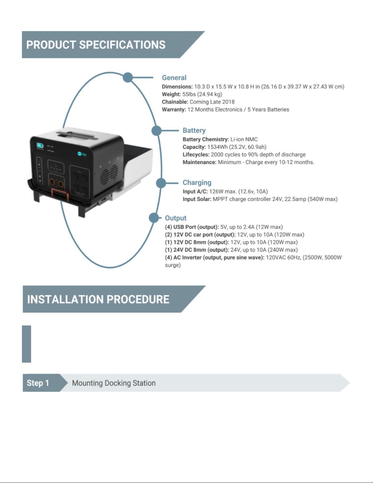
ClearEnergy P2 User manual


Thank you for purchasing a ClearEnergy P2. The
ClearEnergy P2 ensures that your home’s essentials are
powered during the event of a power outage and you also
have portable power wherever you are and for all your
on-the-go-needs.
●ClearEnergy P2 is an all-in-one plug-n-play energy
charging, storage and powering solution. It can power
refrigerators, lights, TV’s, internet modems, microwaves,
fans and more if your home loses power from the grid or
if you need power on the go.
●ClearEnergy Docking station integrates the P2 into your
homes breaker panel and circuits to automatically charge
via grid or solar and power up to 3 essential load circuits
(15 amps each).
CAUTION Hazardous voltages are present inside ClearPOWER P2, Docking station and Breaker panel
enclosures that can cause death or severe personal injury. Follow proper installation, operation and
maintenance procedures to avoid hazardous voltages. Turn off the main circuit breaker in the load
center before starting installation.
1. Identify installation location of the Docking Station. Most installations are done in utility rooms in proximity
to the home’s breaker panel.
2. Use Template to mark the lag locations that correspond with the lag holes on the back of the docking
station and the hole for the provided power whip (called the ClearEnergy installation cable).
3. Make sure lags will screw into studs or other secure surface.
4. Cut hole where the ClearEnergy installation cable will attach.

5. Attach ClearEnergy installation cable to the Docking Station.
6. Screw lags into studs 80% on previously marked location.
7. Hang Docking Station using “Eyelet holes” that are pre-drilled and located on the back of the Docking
Station
8. Tighten lags completely.
1. Fish other end of ClearEnergy installation cable to 4 Square location.
2. Attach 4 Square Box to ½” knock-out and secure using locking.
3. Mount 4 Square Box.
1. Identify 3 critical circuits to be backed-up by the ClearEnergy ClearPOWER P2.
2. De-energize panel breakers.
3. Run wires from the panel protected in conduit, Sealtite, Flex or other appropriate means to the 4 Square
Box.
4. Label and Mark wires according to the provided wiring diagram in order to easily match with the labeled
wires on the ClearEnergy installation cable.
5. Connect to corresponding wires on the ClearEnergy installation cable located in the 4 Square Box.
6. Connect corresponding wires (hot, neutral and ground) to the breakers following the provided wiring guide
and wire numbers.
7. Energize the breaker panel and test.
1. Run PV wire from the solar panels, through appropriate conduit, to the 4 Square Box.
2. Install disconnect to the PV power cables.
3. Ensure disconnect is off.
4. Follow the provided wiring guide connect PV power cables to the ClearEnergy installation cable in the 4
Square Box.
5. Turn disconnect switch on and energize the circuit.
6. Test
***Optional and purchased separately. Used for connecting to existing solar arrays with micro-inverters
and/or optimizers.
1. Find and identify ideal mounting location for relay box on rooftop rack mounting.
2. Identify up to 3 optimal panels to use for wiring into the ClearEnergy Docking Station to charge
theClearEnergy ClearPOWER P2.
3. Using MC4 connectors and Y Branch connector to split the + and – leads from each solar panel before the
micro-inverter and/or optimizer.
4. Attach the + and – leads to the relay box.
5. Using approved methods bring #10 AWG wire from the ClearEnergy RelayBox to the installed 4 Square Box
dedicated to the ClearEnergy DockingStation.
6. Run outside rated #18 AWG (signal wires) from the ClearEnergy RelayBox to the 4 Square box dedicated to
the ClearEnergy DockingStation.
7. Connect solar wires in the RelayBox and junction box.
8. Connect the signal wires in the RelayBox and in the Junction Box.
9. Re-install plates and re-mount solar panels
10. Test
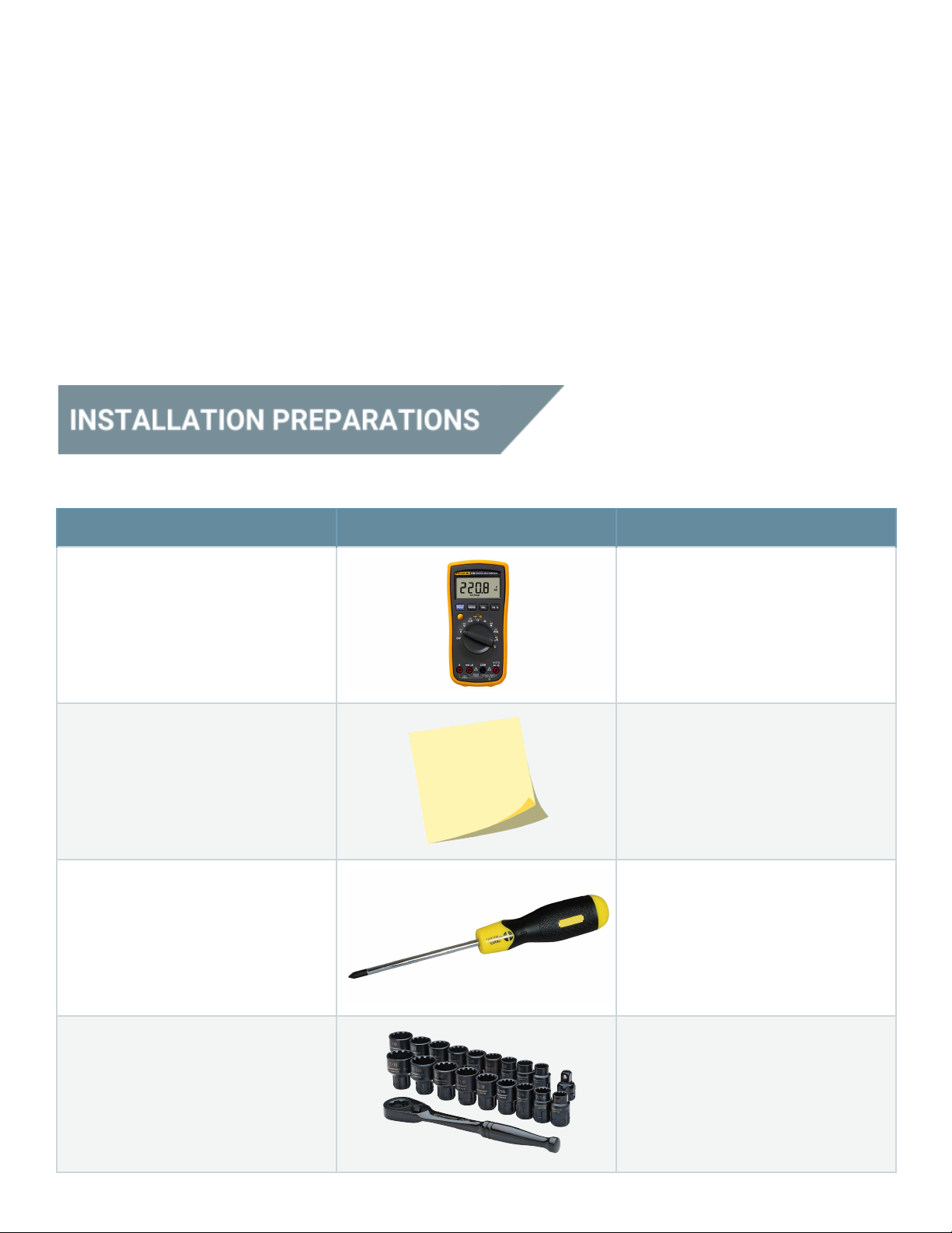
Tool
Appearance
Description
Multimeter
Used to check cabinet insulation
and cable connection, and
measure electronic performance
specifications of a device, such as
voltage, current, and resistance.
Label paper
Used to prepare labels.
Insulated phillips screwdriver (2
mm x 150 mm and 3 mm x 250
mm)
Used to tighten screws and bolts.
Insulated socket wrench
Used to tighten bolts and nuts.

COAX crimping tool
Used to crimp cord end terminals.
Diagonal pliers
Used to cut insulation cables and
cable ties.
Wire stripper
Used to remove the insulation
layer and jacket from a
communication cable with a small
cross-sectional area.
PVC insulation tape
Used to insulate wires and
conductors.
Cotton cloth
Used to clean panels and shells.
Heat shrink tubing(M6)
Used to insulate wires and
conductors.
Heat gun
Used to heat a heat shrink tubing.
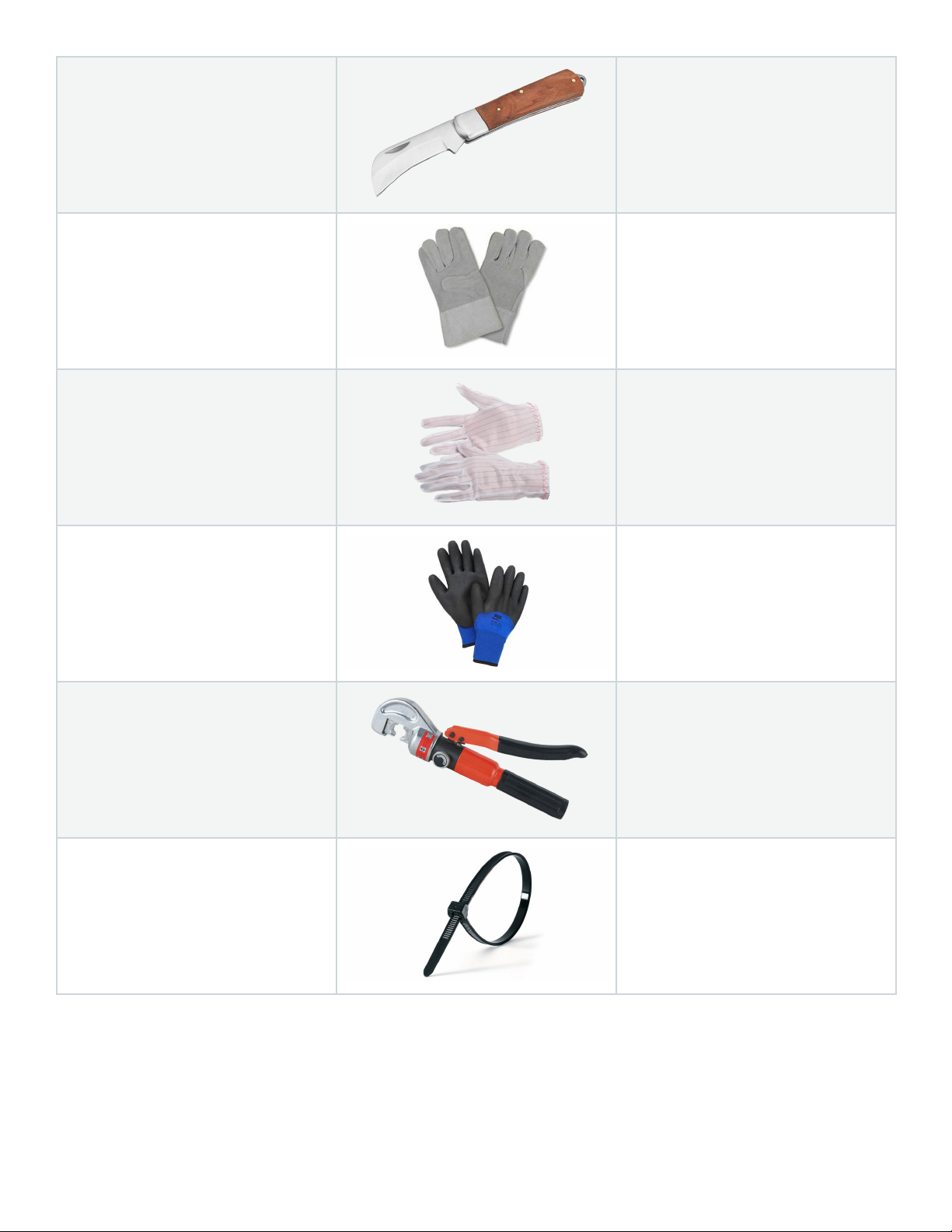
Electrician's knife
Used to strip cables.
Protective gloves
Used to protect hands and the
device on which you operate.
ESD gloves
Used to prevent the electrostatic
discharge (ESD) from damaging a
board or other electrostatic
sensitive devices (ESSDs) when
you insert or remove a board or
hold an ESSD.
Insulated gloves
Used to insulate hands.
Hydraulic pliers
Used to crimp the OT terminals
and JG terminals with a large
cross-sectional area of 10 mm2,
16 mm2, 25 mm2, or 35 mm2.
Cable tie
Used to bind cables.
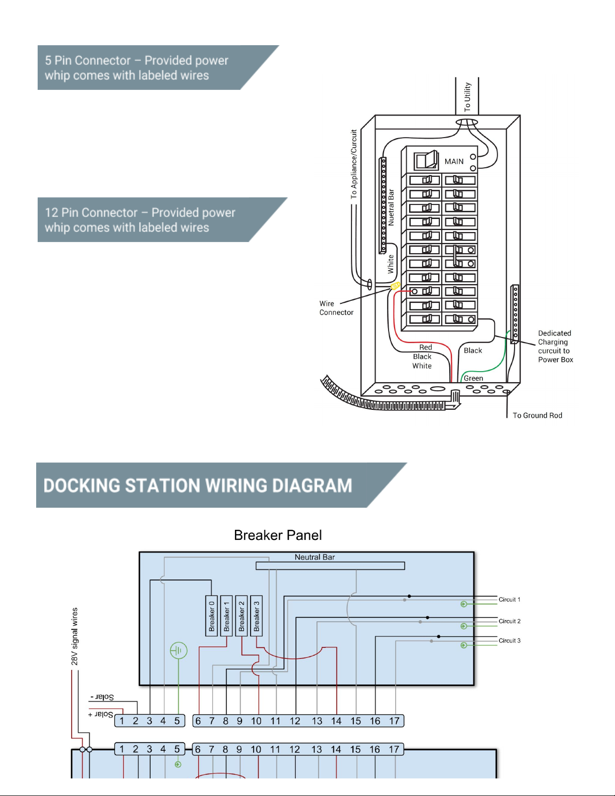
1. PV Wire + (Red) #10 AWG
2. PV Wire – (Black) #10 AWG
3. Control Wire (Purple) #18 AWG
4. Control Wire (Orange) #18 AWG
5. Ground (Green) # 6 AWG
1. Power to Docking Station (Black) #14 AWG
2. Neutral to Docking Station (White) #14 AWG
3. Circuit #1 From Breaker (Red) #12 AWG
4. Circuit #2 From Breaker (Red) #12 AWG
5. Circuit #3 From Breaker (Red) #12 AWG
6. Appliance/Circuit #3 (Black) # 12 AWG
7. Neutral #1 to Neutral Bar (White) #14 AWG
8. Appliance/Circuit #2 (Black) #12 AWG
9. Neutral #2 to Neutral Bar (White) #14 AWG
10. Appliance/Circuit #1 (Black) # 12 AWG
11. Neutral #3 to Neutral Bar (White) #14 AWG
12. Empty
Popular Batteries Charger manuals by other brands


Compleo
Compleo DUO bm operating instructions

Horizon Hobby
Horizon Hobby Smart Technology S120 instruction manual

Hama
Hama Xbox360 Operating instruction

Casio
Casio DT-9721CHGE user guide

Lester
Lester Lestronic II troubleshooting guide

AMX
AMX Rechargeable Upgrade Kit and Charging Base... installation guide


