Clearfield FieldSmart Makwa FDH User manual
FieldSmart®Makwa FDH
Installation Manual ______________________________________________________
Manual 017526 REV E - April 2018

Direct: 763.476.6866 • National: 800.422.2537 • www.SeeCleareld.com • [email protected]
2
FieldSmart®Makwa FDH
Installation Manual _________________________________________________________
Manual 017526 REV E - April 2018
Table of Contents
Application 3
Description 3
Technical Specications 3
Product Packaging 4
Designation Cards 6
Below Grade Installation 7
Optional Step Rack and Manual Mounting Brackets 8
Vault Installation Procedure 9
Vault Access and Storage 11
Makwa Swing Arm 14
Above Grade Installation 20
Dome Removal 22
Designation Card Installation 23
Dome Installation 24
Schrader Valve 26
Patch and Splice 27
Clearview Black Cassette 32
Storing Buffer Tube After Splicing 35
PON Splitters 37
Cross-Connect Patch Cords 41
Connector Cleaning Procedure 43
Standard Warranty 46
Proprietary Notice 47
Technical Support 47
3
FieldSmart®Makwa FDH
__________________________________________________________ Installation Manual
Direct: 763.476.6866 • National: 800.422.2537 • www.SeeCleareld.com • [email protected]
Manual 017526 REV E - April 2018
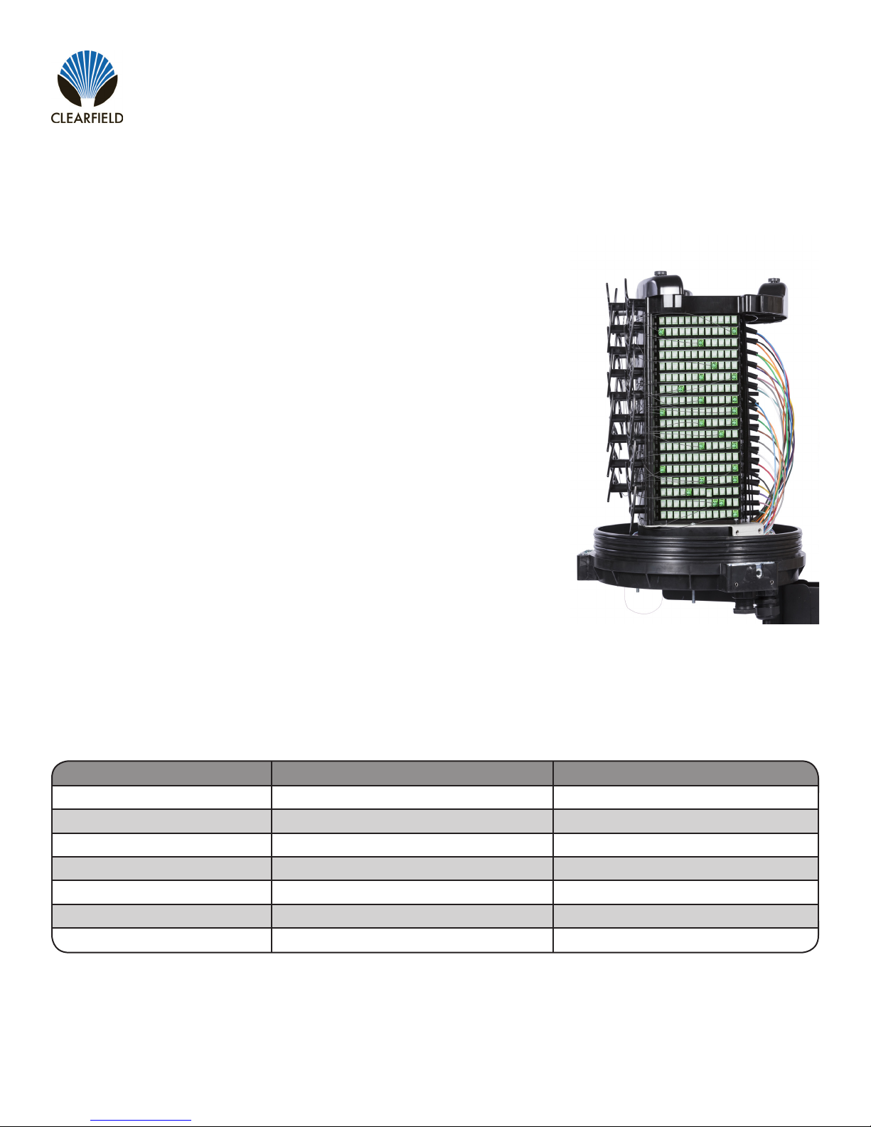
The FieldSmart Makwa, incorporates all of the features found in our above
ground cabinets and adds the ability to deploy the FieldSmart FSC Distribution
Hub in a below grade application. Roughly 50% smaller than existing above
grade cabinets, Makwa reduces real estate costs and improves density without
compromising critical design elements of accessibility, bend radius protection,
physical ber protection and route path diversity.
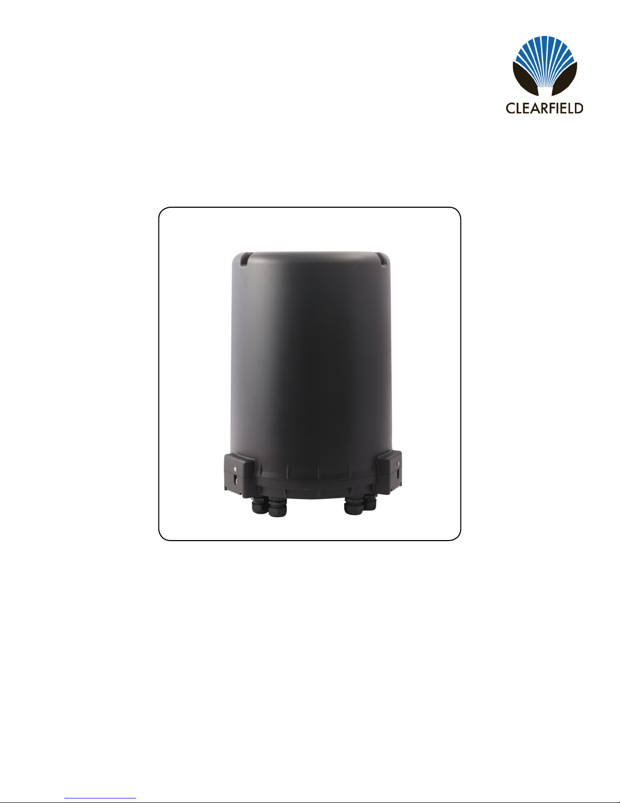
Cleareld’s FieldSmart Makwa consists of four basic elements; top over
(dome), base plate, internal backplane and Clearview Black Cassettes. All
components are pre-assembled and loaded into the Makwa – making it eld
ready for deployment. Scalable to meet customer requirements, Makwa can
be congured to accept 12-48 feeder ports and 12-288 distribution ports in a
PON application. It will accept up to nine (9) 1 x 32 ruggedized splitters and two
(2) staging plates for PON networks. For cross connect scenarios, Makwa can
accommodate 12-432 ports as required.
Providing 12-432 ports of connectivity for either PON or Cross-Connect, utilizing
patch and splice or patch only technology in any network environment. The
FieldSmart FSC Makwa is scalable to meet customer’s specic requirements
and has the ability to be mounted either above or below-ground, taking the
potential above grade aesthetics issue out of the deployment equation
Description
Application
Technical Specications
288 PON Makwa 432 Cross-Connect Makwa
Dimensions 22 3/8” H x 16” W x 16” D 22 3/8” H x 16” W x 16” D
Splicing Yes - Clearview Black Cassette Yes - Clearview Black Cassette
Feeder/Express Ports Up to 48 Up to 216
Distribution Ports Up to 288 Up to 216
Cable Entrances 4 4
Splitter Slots 9 N/A
Jumper Length N/A 1.2 meters
Direct: 763.476.6866 • National: 800.422.2537 • www.SeeCleareld.com • [email protected]
4
FieldSmart®Makwa FDH
Installation Manual _________________________________________________________
Manual 017526 REV E - April 2018
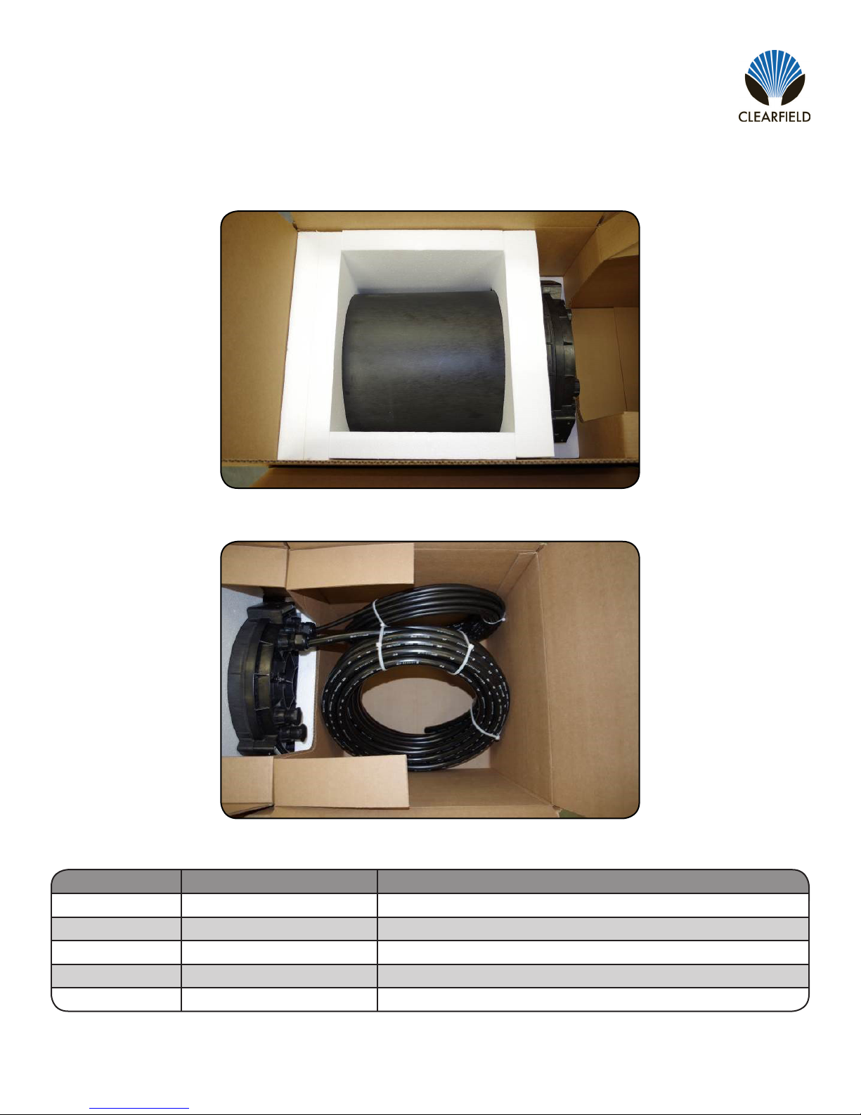
Product Packaging
Patch and Splice Packaging
Patch Only Packaging
Quantity Part Number Description
1 017271 Makwa Key, T-Handle 5/16 Hex Wrench - 9” Length
4 017466 1” Sealcon Fitting with Various Grommet Inserts
4 017468 1” Plug Fitting
1003042 30” Roll of 1” Wide Grommet Tape
1 016096 10 Feet of Snakeskin Sleeving (Patch and Splice)
Included Accessories List: (Some parts may already be installed for patch only congurations)

5
FieldSmart®Makwa FDH
__________________________________________________________ Installation Manual
Direct: 763.476.6866 • National: 800.422.2537 • www.SeeCleareld.com • [email protected]
Manual 017526 REV E - April 2018
Packaging Removal
Open the enclosure following the dome removal procedure.
Remove the foam inserts holding the cassettes in place (Figure 1).
Note: The foam inserts can be saved and used as supports if desired.
Step 1:
Step 2:
Step 3:
Figure 1
Cut the zip ties holding the cassettes during shipping (Figure 2).
Figure 2
Direct: 763.476.6866 • National: 800.422.2537 • www.SeeCleareld.com • [email protected]
6
FieldSmart®Makwa FDH
Installation Manual _________________________________________________________
Manual 017526 REV E - April 2018
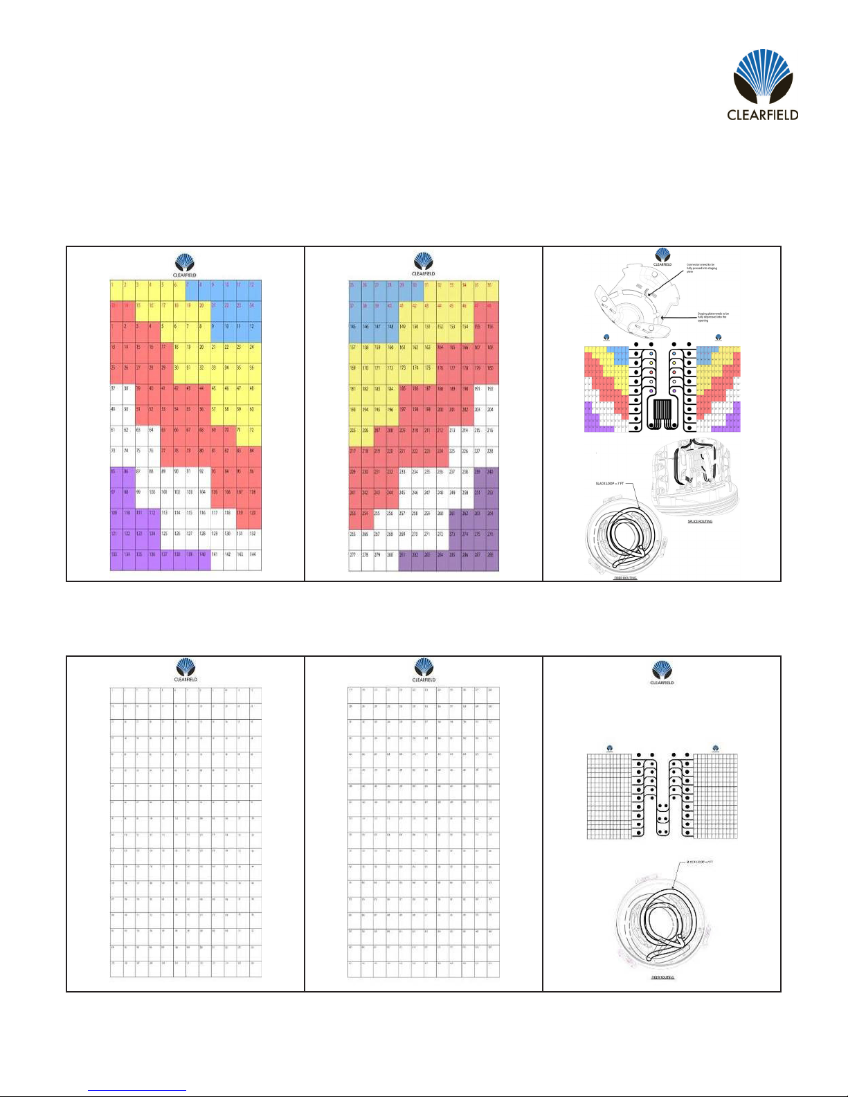
Designation Cards
The Makwa FDH is set up for either a PON or Cross-Connect application. Please refer to the appropriate designation and
application cards that will be utilized for ber protection when the dome lid is placed.
PON Designation Cards
Cross-Connect Designation Cards
Desi Card - Left Desi Card - Right Application Card - Center
Desi Card - Left Desi Card - Right Application Card - Center
7
FieldSmart®Makwa FDH
__________________________________________________________ Installation Manual
Direct: 763.476.6866 • National: 800.422.2537 • www.SeeCleareld.com • [email protected]
Manual 017526 REV E - April 2018
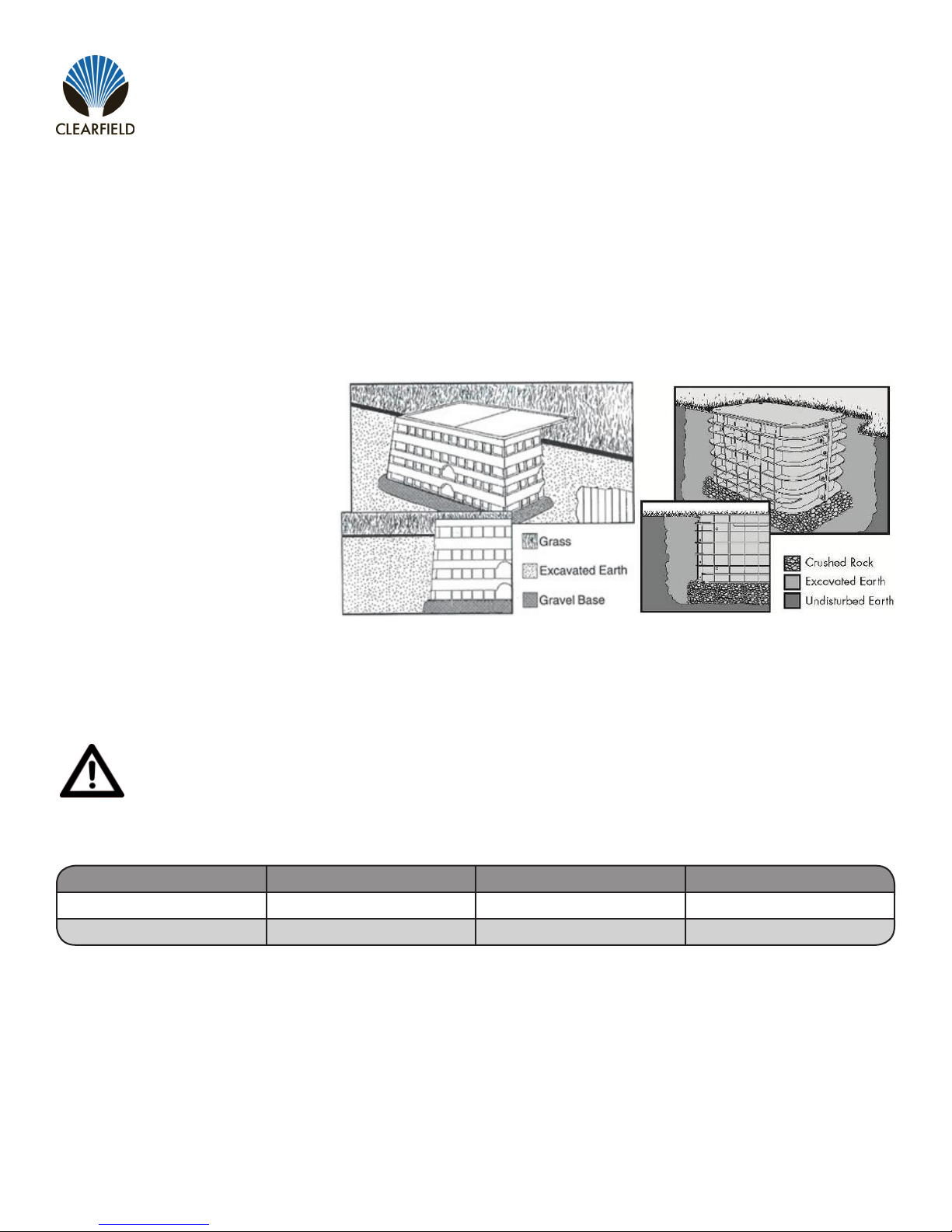
Below Grade Installation
Parkway Vault Installation
Installation instructions provide general information useful for parkway placement in “grass surround”, grass, dirt, or
gravel applications. This guide cannot anticipate all situations that could develop in the eld. Rather, it represents
information applicable to common installation conditions.
Installation Location
Location alone should not dictate
product selection. “Pedestrian loading,”
sometimes referred to as “Greenbelt”,
denes our HDPE thermoplastic body
and covers vaults are intended for in-
stallation in landscape or grass surround
areas where they will not be exposed to
vehicular trafc. Exceptions to this rule
include residential or light commercial
mowers but do now include tractor/
mowers in highway easements.
Site Preparation
Ensure that national – local electrical and building codes, OSHA and company safety work rules are observed and
provisions made for street ags, barricades and cones. Secure permits as required by city and company.
Warning: Buried Telecommunications Cables. Be sure to call 811 at least 30 days in advance before digging.
Calling 811 will route to the local one-call center and ensure that utilities in the area of installation will be located
and marked.
Recommended Vault Sizes
Vault Size HDPE Solid Lid HDPE Split Lid Polymer Concrete
30” W x 48” L x 36” D V7B-AZP V7B-BZP V7B-EZP
36” W x 60” L x 36” D N/A V8B-BZP-F* V8B-EZP-F*
*Vaults must be straight walled to use brackets and step rack on swing arm. These vaults are ared walled so Makwa will
sit on bottom of vault (for vault with swing arm see page 17).
Note: Vault size is generally dened by the approximate cover dimensions. The vault actual measurements will differ. The
dimensions above for determining the size of excavation provide sufcient volume for accommodating the maximum recom-
mended select backll.
Direct: 763.476.6866 • National: 800.422.2537 • www.SeeCleareld.com • [email protected]
8
FieldSmart®Makwa FDH
Installation Manual _________________________________________________________
Manual 017526 REV E - April 2018
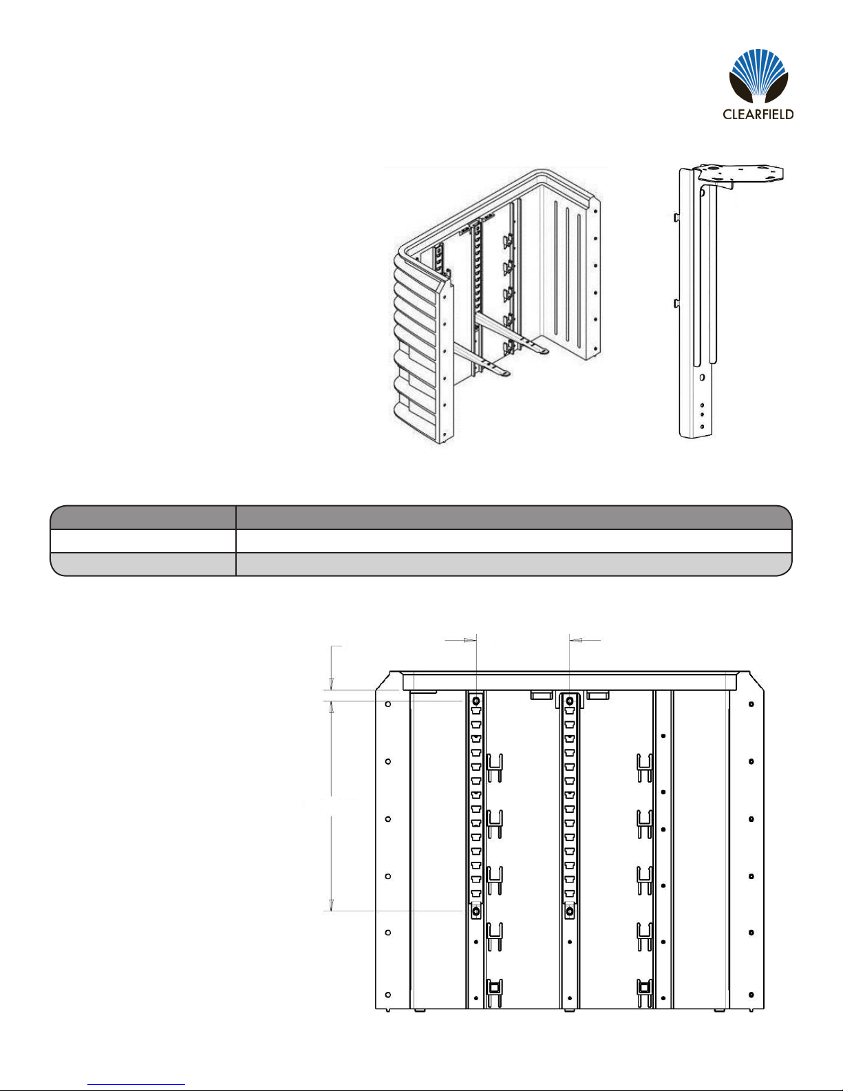
Optional Step Rack and Manual Mounting Brackets
Part Number Description
017202 Kit, In Vault Mounting Kit for Makwa, includes two 24” step racks and two 18” cable hooks *
016897 Bracket, In Vault Mounting Stand for Makwa *
If the Makwa Swing Arm (see page 20) is not used,
the optional Step Rack Mounting Bracket & Manual
Mounting Bracket may be deployed to install Makwa
inside of vault.
When using the optional step rack mounting bracket,
the step racks need to be installed onto the vault
before burying the vault in the ground.
Note: The step rack mounting bracket kit comes with
the required mounting hardware.
Makwa Mounting Kit (P/N 017202) Makwa Manual Mounting
Bracket (P/N 016897)
* Both items need to be ordered together
Step Rack Mounting Location
Note: The step rack arms should
be installed in one of the two bottom
steps to ensure the enclosure ts
with the vault lid installed.
1.17”
22.4”
10.0”

9
FieldSmart®Makwa FDH
__________________________________________________________ Installation Manual
Direct: 763.476.6866 • National: 800.422.2537 • www.SeeCleareld.com • [email protected]
Manual 017526 REV E - April 2018
Vault Installation Procedure
Excavate hole to appropriate dimension with
mechanical excavator or hand dig as appropriate
(Figure 1).
Note: Plan excavation approximately twelve to
sixteen inches longer and wider than the actual
dimensions of the vault being installed. Similarly,
excavate six to eight inches deeper than the overall
dimensions of the vault with cover in place.
Step 1:
Figure 1
Figure 3
Figure 2
Use a minimum three to ve inches of crushed rock
to prevent subsidence over time (Figure 2).
Note: Base material shall be crushed rock 3/4”
and smaller, and not “river rock” or “round stone.”
Desired compaction and equivalent resistance to
lateral loading will not be achieved with round stone.
The rock should be free of soil and organic material.
Step 2:
Set vault on top of backll material and adjust height
to grade (Figure 3). Tamp base material to level with
a mechanical tamper or hand tamper. When a vault
must be installed on a hill, a retaining wall provision
shall be made. The cover of the enclosure shall be
at or to nal grade as specied by the Owner/
Operator. Soil in the immediate vicinity shall be
tamped and sloped away from the enclosure.
Step 3:

Direct: 763.476.6866 • National: 800.422.2537 • www.SeeCleareld.com • [email protected]
10
FieldSmart®Makwa FDH
Installation Manual _________________________________________________________
Manual 017526 REV E - April 2018
Center the vault in the excavation parallel with side-
walk or curb. Mark the vault for duct entry and step
rack locations. The vault may be cut with a hole saw
and drill (Figure 4). The duct may also come up
from underneath the vault, where-as no holes need
to be drilled
Note: Make sure to provide adequate clearance
for ovality in ducts. The small clearance between
the duct and vault may be sealed with expanding
polyurethane foam
Step 4:
Figure 6
Figure 5
Figure 4
Replace the cover on the vault before backlling
(Figure 5).
Note: Bolting the cover in place is recommended,
but not required during backll.
Begin the backlling operation by adding soil,
crushed rock or dry lean mix in eight inch (8”) lifts
or layers. A mechanical tamper may be used. The
tamped crushed rock supports the vault, preventing
subsidence and providing for drainage.
Note: Backll material can vary based on product
and installation location. It is customary and
acceptable in landscape installations where vehicles
are prevented from trafc on or around a vault to use
the soils removed during excavation for backll
(Figure 6). Make sure to remove stones three
inches and larger, prior to backll.
Take care not to damage vault during backll. Cover
may not t properly if vault is damaged.
Step 5:
Step 6:
11
FieldSmart®Makwa FDH
__________________________________________________________ Installation Manual
Direct: 763.476.6866 • National: 800.422.2537 • www.SeeCleareld.com • [email protected]
Manual 017526 REV E - April 2018
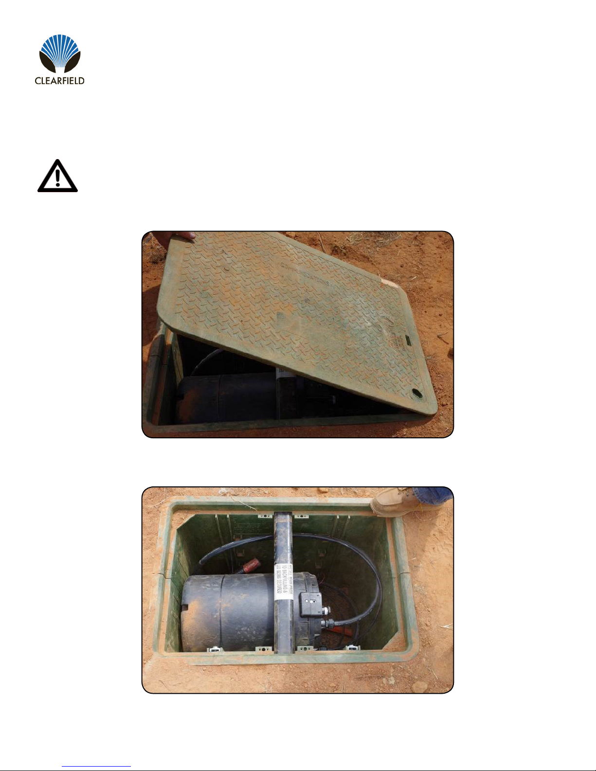
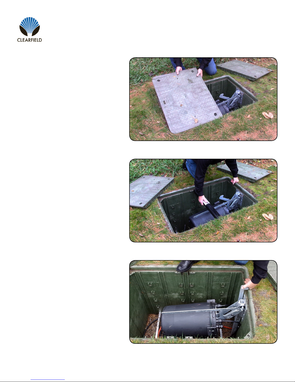
Vault Access and Storage
The following instructions apply only to Step Rack and Manual Bracket installation. Does not apply to Swing Arm installation.
Warning: : Make sure you read the warning labels before removing the enclosure. If there is water in the vault,
the water must be completely drained or pumped out of the vault prior to removing/reinstalling the Makwa.
Figure 1
Figure 2
Remove vault lid support beam (Figure 2).Step 2:
Remove vault lid (Figure 1).Step 1:
Direct: 763.476.6866 • National: 800.422.2537 • www.SeeCleareld.com • [email protected]
12
FieldSmart®Makwa FDH
Installation Manual _________________________________________________________
Manual 017526 REV E - April 2018
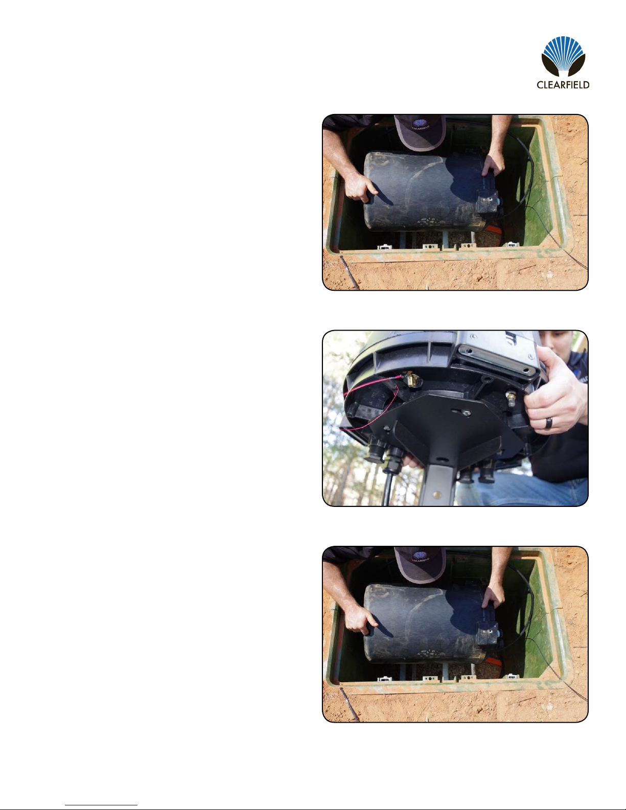
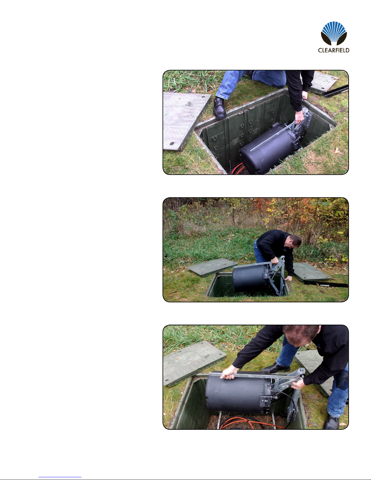
Lift the Makwa out of the vault (Figure 3).Step 3:
Figure 5
Figure 4
Figure 3
Place Makwa on Mounting Bracket (P/N
016897) to perform maintenance (Figure 4).
When you have completed your maintenance,
follow the steps below to replace the Makwa
back in the vault.
Carefully lower the Makwa into the vault (Figure
5).
Note: Maintain proper cable bend radius when
lowering the enclosure into the vault.
Step 5:
Step 4:

13
FieldSmart®Makwa FDH
__________________________________________________________ Installation Manual
Direct: 763.476.6866 • National: 800.422.2537 • www.SeeCleareld.com • [email protected]
Manual 017526 REV E - April 2018
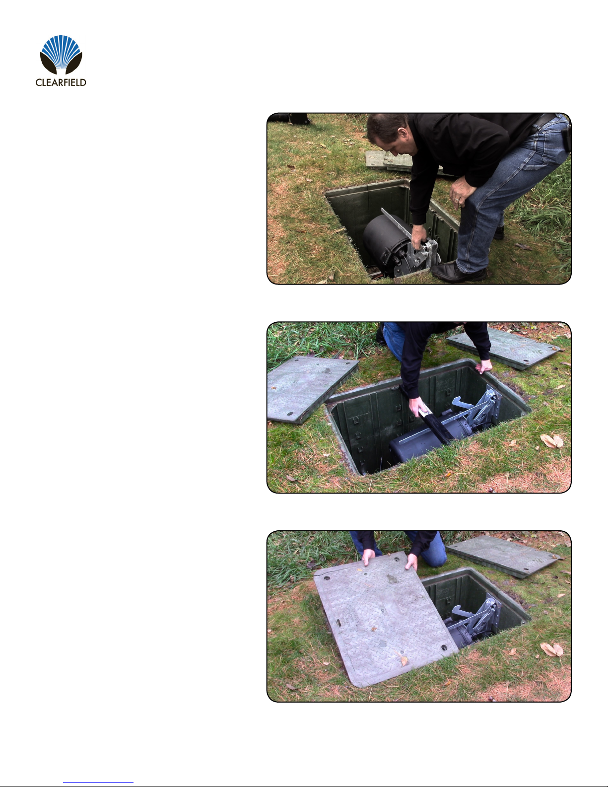
Secure the enclosure to the step rack using
zip ties (Figure 6).
Step 6:
Figure 8
Figure 7
Figure 6
Step 7:
Step 8:
Install vault lid support beam (Figure 7).
Install and secure the vault lid (Figure 8).

Direct: 763.476.6866 • National: 800.422.2537 • www.SeeCleareld.com • [email protected]
14
FieldSmart®Makwa FDH
Installation Manual _________________________________________________________
Manual 017526 REV E - April 2018
Makwa Swing Arm
When below grade mounting is required, the Makwa swing arm provides below grade vault protection, while allowing easy
access for ber maintenance. The swing arm is available preinstalled in approved vault sizes or as a stand alone accessory
that can be mounted into existing straight-sided vault.
Part Number Description
V7B-AZP-SARM Vault, below grade Pencell, 30 x 48 x 36”, solid HDPE lid, hex bolts, green, straight wall,
with swing arm
V7B-BZP-SARM Vault, below grade Pencell, 30 x 48 x 36”, split HDPE lid, hex bolts, green, straight wall,
with swing arm
V7B-EZP-SARM Vault, below grade Pencell, 30 x 48 x 36”, split polymer concrete lid, hex bolts, green,
straight wall, with swing arm
Installing Swing Arm in an Existing Vault
Part Number Description
016897 Bracket, In Vault Mounting Stand for Makwa *
017202 Kit, In Vault Mounting Kit for Makwa, includes two 24” step racks and two 18” cable hooks *
VA-SWING-ARM Swing arm for Makwa
* Both items need to be ordered together
The Makwa Swing Arm can be installed in any straight sided vault large enough
to accommodate the Makwa and swing arm (dims?) by using the hardware
provided in the vault mounting kit as shown below.
15
FieldSmart®Makwa FDH
__________________________________________________________ Installation Manual
Direct: 763.476.6866 • National: 800.422.2537 • www.SeeCleareld.com • [email protected]
Manual 017526 REV E - April 2018
Raising the Makwa Swing Arm
Figure 3
Figure 2
Figure 1
Remove the vault lid (Figure 1).Step 1:
Step 2:
Step 3:
Remove vault lid support beam
(Figure 2).
Disengage kick bar by pressing it
away from central support beam
(Figure 3).
Direct: 763.476.6866 • National: 800.422.2537 • www.SeeCleareld.com • [email protected]
16
FieldSmart®Makwa FDH
Installation Manual _________________________________________________________
Manual 017526 REV E - April 2018
Figure 6
Figure 5
Figure 4
With kick bar depressed, grip the
swing arm near the base, between
the horizontal support beam and the
hinge, lift up on unit (Figure 4).
Step 4:
Step 5:
Step 6:
Continue lifting until unit locks into
place (Figure 5).
Now, gripping the swing arm near
the top, release the locking catch by
pressing upward (Figure 6).
Note: If the swing arm piston
becomes corroded, tap the arm
lightly with a mallet until piston
mechanism frees up.

17
FieldSmart®Makwa FDH
__________________________________________________________ Installation Manual
Direct: 763.476.6866 • National: 800.422.2537 • www.SeeCleareld.com • [email protected]
Manual 017526 REV E - April 2018
Figure 1
Figure 8
Figure 7
With the catch released, lift up on
the swing arm until it locks in the
vertical position (Figures 7 & 8).
Step 7:
Step 1: Grip the swing arm near the top and
push the unit forward.
Lowering the Makwa Swing Arm

Direct: 763.476.6866 • National: 800.422.2537 • www.SeeCleareld.com • [email protected]
18
FieldSmart®Makwa FDH
Installation Manual _________________________________________________________
Manual 017526 REV E - April 2018
Figure 4
Figure 3
Figure 2
Pull back on locking catch to
partially lower the unit (Figure 2).
Step 2:
Step 3:
Step 4:
Locking catch will engage again at
the mid-point of descent. Lift up on
the locking catch to continue
descent to horizontal position.
(Figure 3).
Grip the swing arm near the base,
between the horizontal support
beam and the hinge, and disengage
kick bar by pressing it away from
central support beam (Figure 4).
19
FieldSmart®Makwa FDH
__________________________________________________________ Installation Manual
Direct: 763.476.6866 • National: 800.422.2537 • www.SeeCleareld.com • [email protected]
Manual 017526 REV E - April 2018
Figure 7
Figure 6
Figure 5
Lower unit into vault (Figure 5).Step 5:
Step 6:
Step 7:
Replace central strength member
arm (Figure 6).
Replace and secure vault cover
(Figure 7).
Direct: 763.476.6866 • National: 800.422.2537 • www.SeeCleareld.com • [email protected]
20
FieldSmart®Makwa FDH
Installation Manual _________________________________________________________
Manual 017526 REV E - April 2018
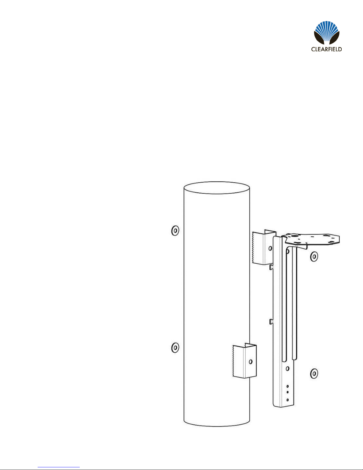
Above Grade Installation
Pole Mount Kit
The FieldSmart Makwa FDH is approximately half the size of a conventional Fiber Distribution Hub, allowing the broadband
service provider the choice of where to deploy the cabinet without sacricing performance or access. The Makwa FDH Pole
Mount Kit allows both the 288 port PON and 432 port cross-connect versions to be pole mounted, while providing access to
the FDH for moves, adds, and changes.
Required Items (Customer Supplied):
• Quantity 4 - Stainless Steel or Galvanized Washers and Nuts
• Quantity 2 - Stainless Steel or Galvanized 5/8” Threaded Rod (Minimum Diameter)
Note: Length determined by diameter of pole - It
is suggested to add 3” to the diameter of pole for
rod length. Cleareld does not recommend using
lag bolts to mount the bracket to the pole.
Assembly Diagram
FieldSmart Makwa Pole Mount Kit (P/N 016902)
This manual suits for next models
2
Table of contents
Other Clearfield Network Accessories manuals


