Clearpond ETERNITY Series Reference guide

ETERNITY PUMP
S
ERIES
Madein EUfor
Clearpond, 17 Discovery Drive, Bibra Lake,
Western Australia
6163
www
.clearpond.com.au
ETERNITY
9000
ETERNITY
7000
ETERNITY
4000
ETERNITY
3000
ETERNITY
2000
ETERNITY
1400
ETERNITY
800
Customer
Manual
Index
1. Overview
4
2. General instructions and information for the user
5
3. Product description
6
4. Technical data and characteristics
6
5. Installation
6
6. Operation and use
7
7. Ordinary, scheduled and extraordinary maintenance
7
8. Problem resolution
8
9. Trade components, spares and relevant documentation
8
1

2
Fig. 3
Fig. 4
Fig. 5
Fig. 6
Fig. 7
Fig. 8
Fig. 9
Fig. 10
ETERNITY 9000/7000 ETERNITY 3000/4000 ETERNITY 1400/2000 ETERNITY 800
Figure 1
ETERNITY 9000/7000 ETERNITY 3000/4000 ETERNITY 1400/2000 ETERNITY 800
Figure 2

3
Fig. 3
Fig. 4
Fig. 5
Fig. 6
Fig. 7
Fig. 8
Fig. 9
Fig. 10
W[W] Q[l/h] H[m] Kg A B C
ETERNITY 9000 140 9000 4.0 2,58 kg 124 mm 111 mm 243 mm
ETERNITY 7000 130 6500 3.9 2,58 kg 124 mm 111 mm 243 mm
ETERNITY 4000 65 4000 3.7 2,16 kg 126 mm 111 mm 223 mm
ETERNITY 3000 60 3000 3.2 2,16 kg 126 mm 111 mm 223 mm
ETERNITY 2000 40 2000 2.3 1,80 kg 100 mm 79 mm 158 mm
ETERNITY 1400 35 1400 2.1 1,80 kg 100 mm 79 mm 158 mm
ETERNITY 800 14.5 800 1.3 1,23 kg 78 mm 65 mm 125 mm
Table 1

4
# (Fig. 1) Model Code
1+2+3
ETERNITY 800 XR271N
ETERNITY 1400
XR272N
ETERNITY 2000
ETERNITY 3000
XR273N
ETERNITY 4000
ETERNITY 7000
XR274N
ETERNITY 9000
4+5+6
ETERNITY 3000 XR175B
ETERNITY 4000 XR195B
ETERNITY 7000 XR197B
ETERNITY 9000 XR201B
4+5+7
ETERNITY 800 XR120B
ETERNITY 1400 XR130B
ETERNITY 2000 XR140B
7+5
ETERNITY 3000
XQ101B
ETERNITY 4000
ETERNITY 7000
XQ103B
ETERNITY 9000
Table 2
Spare Parts
Instructions
1. Overview
1.1 Symbols
Shows danger situations and warnings. It is necessary to read the customer manual parts showing this
symbol with maximum care.
Shows that no works can be performed on the equipment while it is connected to a power source. It is
possible to start working on the equipment only after adopting the appropriate safety measures as described
in the international and/or national regulations in force from time to time.
1.2 Glossary.
Inlet: the pump’s entry (Figure 1, IN).•
Outlet: the pump’s exit (Figure 1, OUT).•
Bearing: this is a mechanical device used to reduce attrition between two rotating objects (Figure 1, # 6).•
Dry operation: means the pump’s operation without water.•
Rotor: it indicates all the rotating components of the pump (Figure 1, # 4).•
Impellor: The front part of the rotor, made up of a plastic disc with small blades. With its rotation, it•
transmits to the water the necessary mechanical energy to move water from the inlet to the outlet area.
Residual Current Device: also called a circuit-breaker, this is an technical device that can break a circuit•
in the event of a failure.
Thermal protector: a device that interrupts the power supply to the product when the latter overheats.•
Hydraulic parts: parts used to build the system that includes the product (pipes, valves, joints, etc.).•
Home pond: a vessel and / or construction used to contain water.•
Waterfall: water falling down because of a difference in altitude.•
Filter: a device water is sent through in order to retain and/or eliminate solid particles suspended in the•
water itself.
Pond skimmer: a filter that keeps the home pond surface clean.•
Flowrate: the amount of water that crosses a certain section in one time unit.•
Head: this is the maximum distance that a pump can lift water for.•
Power plug: a mechanical connector that can be introduced in a complementary (power outlet).•

5
2. General instructions and information for the user.
2.1 Guarantee.
2.1.1 Generalities.
i. Pursuant to these provisions, the seller guarantees that the product mentioned in this guarantee (“the
product”) is free of non-conformities at the time of its delivery.
ii. The guarantee period for the product is 3 + 2 (5) years, starting from the moment the product is delivered
to the purchaser. Parts subject to wear and tear, like rotors, are not covered by this guarantee.
iii. The rotor comes with a 2 year guarantee against defects
iv. If the product cannot be repaired or replaced, the purchaser shall have the right to ask for a proportional
price reduction or, if the non conformity is sufficiently serious, to terminate the sales agreement.
v. Replaced or repaired parts under this guarantee shall not prolong the duration of the guarantee for the
original product.
vi. In order for this guarantee to be valid, the purchaser shall have to register the product purchase via the
Clearpond website at www.clearpond.com.au
The guarantee will be honoured only if the unit is returned to your supplier complete, with your receipt
or proof of purchase for the product
vii. If the purchaser claims product non conformities after more than six months from product delivery
to the purchaser, the purchaser shall have to prove the existence and origin of such claimed non
conformities.
viii. This guarantee certificate shall in no way limit or prejudice the consumer’s rights pursuant to national
mandatory regulations.
2.1.2 Special conditions.
i. This guarantee refers to the product described in this customer manual.
ii. This guarantee certificate is applicable exclusively in Australia.
iii. In order for this guarantee to be valid, the purchaser shall have to follow strictly the manufacturer’s
instructions included in the product documentation, in so far as they are applicable to the relevant
product range and model.
iv. If a schedule is given for the replacement, maintenance or cleaning of some product’s parts or
components, the guarantee shall be considered valid only if said schedule has been followed correctly.
2.1.3 Limitations.
i. This guarantee applies exclusively to sales to consumers, “consumers” being the people who buy the
product for purposes that do not concern his or her professional activity.
ii. No guarantee is given concerning normal wear and tear due to the use of the product. With regard to
spares, components and/or replaceable materials or materials subject to wear and tear, such as rotors,
bearings, lamps, o-rings, gaskets, sponges, cartridges, etc., any guarantee shall be enforced pursuant
to the provisions of the product’s documentation.
iii. The guarantee is not valid if the product:
a. has been handled incorrectly;
b. has been repaired, maintained or handled by unauthorised personnel,
c. has had the electrical cable shortened
d. damaged / fault caused by calcium deposits and
e. has been repaired using non original spares.
2.2 Return Goods policy.
In the event of defects, flaws and malfunctions, the product should be returned to the dealer with the claims
card filled out, when present.
2.3 General and safety instructions.
2.3.1 General instructions.
Clearpond is constantly improving its products. Clearpond reserves the right to make technical changes to
the form and accessories of the products.
Please read carefully and hold on to this customer manual.
In the following paragraph you shall find all the necessary instructions to make the best possible use of this
product, according to your needs, and to carry out the small cleaning and maintenance activities required by this
kindofproduct.Thereferences(#)inbracketsrefertothecomponentsshownintheexplodedview(seeFigure1).
Upon product receipt and/or purchase, check packaging integrity. The product must be accompanied by
the customer manual. The customer manual must be complete.
2.3.2 Safety Instructions.
The product is not appropriate for physically, sensory or mentally disabled persons (and children) or for
people without the appropriate skills and knowledge, unless they are instructed on the use of the product
and helped by someone who assumes responsibility for their safety. Monitor children and make
sure that they do not play with the product.
Never put your hands in the water if the pump is in operation.
Be sure to disconnect the power plug from the power outlet before operating on the product.

6
# #
1 Inlet cap 5 Impellor chamber O-ring
2 Front shell 6 Rear bearing
3 Back shell 7 Impellor lid
4 Rotor 8 Motor body
See Figure 1.
3. Product description.
3.1 Product’s aims.
The product you bought is a magnetic drive centrifugal pump, operated by a watertight synchronous motor,
and is the most reliable small pump on the market.
3.2 Structure.
4. Technical data and characteristics.
See Table 2 in Figure 2.
The hydraulic parts used for the building of the system which shall include the product modify the performance
(head and flowrate) of the product.
5. Installation.
5.1 Storage characteristics and conditions.
The product must be stored in a dry place, protected from weather.
5.2 Transport.
Handle the product with care to avoid damages.
5.3 Positioning.
The product must be submersed in a home pond, in an easily accessed position.
It is advisable to take the following into account:
Dimensions and position of hydraulic parts.•
Necessary free space.•
Cable position.•
Location of the power supply (power outlet).•
Support and its location.•
5.4 Connection and commissioning.
The product must be installed and operated by individuals with appropriate training. The electrical system
must meet current international and/or national regulations.
The product must be connected to a power outlet equipped with a residual current device, with a sensitivity
not lower than 30 [mA]. Before starting the product, check that your electrical system is equipped with this
safety device; if necessary, consult a technician.
Check that the product is compatible with the power supply it shall be connected to.
The power outlet must be appropriately far from the water, but easily accessible, so that the product can be
stopped quickly in failure situations. It is strictly forbidden to cut the wire and /or replace the power plug.
The power supply wire must be positioned so as to prevent possible damages, such as torsion and/or cuts.
5.5 Reinstallation and reuse.
Clean the product and the moving parts accurately before stopping the product for a while, such as, for
instance, during the winter months. Do not lubricate and/or use detergents and chemical cleaning products.
5.6 Disassembly and disposal.
Collecting recyclable material, both those used for packaging (cardboard, nylon, etc.) and those replaced
during routine and extraordinary maintenance is recommended. Suitable collection of waste material for
recycling, processing and environmentally compatible disposal contributes in avoiding possible negative
effects on the environment and health and promote the reuse and/or recycling of product materials.
Illicit product disposal by the user may be punishable by current international and/or national laws.
5.6.1 Collection of electric/electronic waste materials.
EU directive 2002/96/EC classifies this product as an electrical or electronic tool.
The barred bin symbol on the equipment or packaging indicates that the product must be separated from
other waste at the end of its working life. Therefore, the user must take equipment to electronic and electro-
technical waste collection centres at the end of its working life or return it to the dealer when purchasing
similar new equipment, on a one to one basis. Suitable collection of decommissioned equipment for
recycling, processing and environmentally compatible disposal contributes in avoiding possible negative
effects on the environment and health and promote the reuse and/or recycling of device materials. Illicit
product disposal by the user may be punishable by current national laws.

7
6. Operation and use.
Do not use glues, sealers or other chemical products on threads or other parts of the product.
6.1 Description of operation.
The product you purchase is designed to move water in home ponds. The rotor turns and transfers water from
the inlet to the outlet. With this product it is possible to feed filters and/or waterfalls (Figure 4 and Figure 8).
6.2 Field of use (Figure 3).
This powerful and reliable product can be used in home pond, together with a filter, for water recirculation
and water features.
6.2.1 Use with lter (Figure 3).
It is possible to use the product to bring water from a home pond to a filter, for instance a pressure filter or a
filter with a germicidal lamp. For this purpose, connect the product’s outlet (Figure 1, OUT) with the filterís entry.
6.2.2 Use with pond skimmer (Figure 4).
The use of the product with a pond skimmer (Figure 5).
In order to use the product in connection with a pond skimmer, please follow the instructions below:
Open the front shell (Figure 1, # 2) and remove the inlet cap (Figure 1, # 1) acting from inside (Figure 6).•
Replace the product’s shell (Figure 1, # 2).•
Mount the hose adapter (Figure 7, this accessory is not included).•
Now use a hose to connect the product’s inlet (Figure 1, IN) with the pond skimmer, and then connect to
the filter (Figure 4).
Never connect the pond skimmer (Figure 3) with the product’s outlet (Figure 1, OUT).
6.2.3 Use with waterfalls (Figure 8).
It is possible to use the product to create a small waterfall, by connecting a hose to the product’s outlet
(Figure 1, OUT) and then running it on top of duly positioned rocks, as shown in Figure 8.
The height of the waterfall shall not exceed the product’s head.
6.3 Use.
Dry operations are prohibited.
Cutting, replacing and/or altering the power cord is strictly prohibited.
6.4 Operational limits and environmental limits.
The product cannot enliven water destined to the human consumption.
Maximum water temperature: 35 [°C].•
Minimum water temperature: 4 [°C].•
Maximum depth of immersion: 1 [m].•
Minimum depth of immersion: 0,1 [m].•
6.5 Safety devices and signalling.
The product is equipped with a thermal protector. Following any thermal protector operation, check the
causes that originated the product’s malfunction.
For this purpose, please consult the “Problem resolution” section.
The product shall go back to normal operating conditions after it has cooled down (about 2-3 hours) and/or
the caused that triggered the thermal protector have been eliminated.
6.6 Dangers and hazards.
Before operating the product, remember that this must always be operated in water and must never be used
when people are in the home pond.
The product is powered electrically and works in the water, so maximum diligence in its installation and
maintenance is required, in order to avoid danger.
Please pay particular attention to:
the conditions of its wire, which must not be damaged;•
the conditions of the rotor, which must always be in optimal conditions.•
7. Ordinary, scheduled and extraordinary maintenance.
Before proceeding with any maintenance activity, remember to disconnect the power plug from the power
outlet, and not to put your hands in the water if the product is turned on.
Product maintenance is limited to the cleaning of the shells (Figure 1, # 2 and 3), of the rotor (Figure 1, # 4)
and of the impellor chamber cover (Figure 1, # 7).
When the performance worsens and at least once a year, it is necessary to check the product and check
the wear of the rotor and bearing and, if necessary, replace worn out parts.
Do not lubricate and/or use detergents and chemical cleaning products.
7.1 Ordinary maintenance.
To be performed at least once a year, or more frequently if necessary.
7.1.1 Shell cleaning.
In order to clean the shells, simply rinse them with abundant water.
In order to make it easier, you may extract the motor body from its seat (Figure 9).

8
PROBLEM CAUSE 1ST SOLUTION 2ND SOLUTION
Low owrate from outlet
The shells are obstructed by dirt Clean the shells
Please consult a
skilled technician.
The product is dirty Clean the product
The hydraulic parts are obstructed
or bent.
Fix the hydraulic parts
The impellor’s blades are worn out. Replace the rotor
The product does not work.
Power supply absent or insufcient. Check the presence of a power
supply.
Please consult a
skilled technician.
The thermal protector has been
triggered.
Check that the water temperature
does not exceed +35 °C and, if
necessary, add cold water to the
pond to lower water temperature.
The power plug is not inserted
correctly into the power outlet.
Insert the power plug better into
the power outlet.
The hydraulic parts are obstructed
or bent.
Fix the hydraulic parts
The shells are blocked by dirt. Clean the shells.
The impellor and/or rotor are
blocked by dirt.
Clean the product.
The rotor and/or bearing are worn
out.
Replace the rotor and/or bearing
The impellor’s blades are worn out. Replace the rotor
Damaged wire Accident and/or negligence. Dispose of the product. -
Damaged rotor and/
or bearing plastic
components.
Wear Replace the rotor and/or bearing. Please consult a
skilled technician.
7.1.2 Rotor cleaning (and/or replacement).
1. Disconnect the impellor chamber Figure 10.
2. Take out the rotor (Figure 1, # 4) paying attention not to lose the impellor chamber O-ring (Figure 1, # 5).
3. Rinse the motor body with lukewarm water, without using any detergents and chemical products
(Figure 1, # 8).
4. Check the wear of the rotor and/or the bearing and replace them if necessary (Figure 1, # 4 and # 6).
5. Reposition the impellor chamber O-ring (Figure 1, # 5) and the rotor (Figure 1, # 4).
6. Hook the impellor chamber.
The rotor’s magnetic field is very strong, so considerable care is required in repositioning it in its seat.
Should the product be used in hard water, it is important to clean the rotor and motor body accurately at
regular intervals. Lime scale can damage the product irreparably.
7.2 Extraordinary maintenance.
Extraordinary maintenance of the product concerns mainly the replacement of the rotor and bearing. Please
follow the instructions in the previous paragraph to replace these parts.
8. Problem resolution.
9. Trade components, spares and relevant documentation.
See Table 1 refer to Figure 1.
This manual suits for next models
20
Table of contents
Popular Pond Pump manuals by other brands
Danner
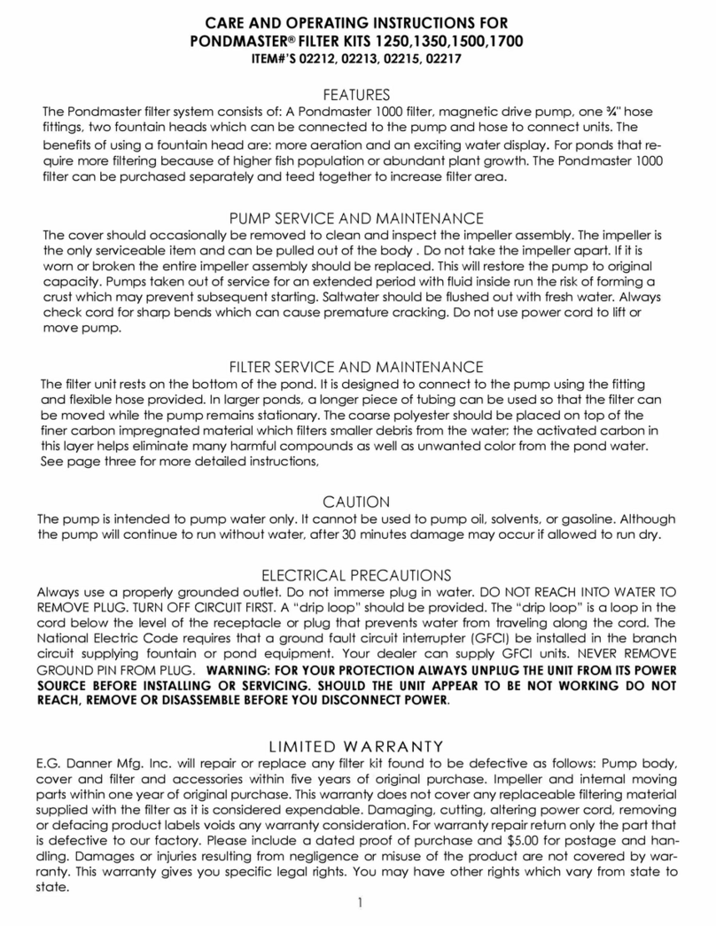
Danner Pondmaster 1250 Care and operating instructions
Biotop Garden
Biotop Garden D0066 User instructions

Oase
Oase AquaOxy 1000 operating instructions
Messner
Messner e-finity Q-Tec 25 operating instructions
TeichTip
TeichTip Sunsun CQP-8000 user manual
Commodity Axis
Commodity Axis ViaAqua EF-3000 UVC instructions
