ClearSpan Storage Master SolarGuard PB00230R4 User manual

ClearSpan™ Storage Master SolarGuard™
42' Wide
Length of the above shelter may differ from your shelter.
Use these instructions for the following building: PB00230R4 (42' W x 17' 3" H x 48' L)
PB00232R4 (42' W x 17' 3" H x 60' L)
PB00234R4 (42' W x 17' 3" H x 72' L)
PB00236R4 (42' W x 17' 3" H x 96' L)
©2006 ClearSpan™
All rights reserved. Reproduction prohibited without written permission.
Revised: February 2006g

Introduction
Thank you for purchasing this ClearSpan™ structure. When properly assembled, the ClearSpan™
structure will provide years of reliable service. This instruction manual includes helpful hints and
important information needed to safely assemble the structure. Please read this instruction manual
before you begin. If you need assistance during construction, call us at 1-800-245-9881.
Safety Precautions
• Wear eye protection.
• Wear head protection.
• Wear gloves when handling metal tubes and cables.
• Use a portable GFCI when working with power tools and cords.
• Do not climb on the shelter or framing during or after construction.
• Do not occupy the shelter during high winds, tornadoes, or hurricanes.
• Provide adequate ventilation if the structure is enclosed.
• Do not store hazardous materials in the shelter without proper ventilation.
• Provide proper ingress and egress to prevent entrapment.
Required Tools
The following list identifies the tools needed to assemble the building. Additional tools and supports
may be needed depending on the structure, location, and application.
• Tape measure or measuring device
• Marker to mark locations
• Electric drill and driver (Battery-powered drivers work best.)
• Metal-cutting saw or tool to cut cable to the required length
• Wrench set to tighten bolts
• Utility knife or scissors
• Ladders, work platform, and other machinery designed to work safely at the height of the
building
• Rope or cable
• Adjustable pliers
• Lifts to set and hold rafters in place
Anchoring Instructions
Prior to assembling the structure, you must read the anchoring precautions and instructions included
with the kit. Anchoring instructions are included in the MUST READ document. You must anchor the
building after the frame is assembled and before the cover is installed.
Visit www.ClearSpan.com for additional products and customer assistance.
1 of 36

Location
Choosing the proper location is an important step before you assemble the structure. The following
suggestions and precautions will help determine whether your selected location is the best location.
• Never erect the structure under power lines.
• Identify whether underground cables and pipes are present before preparing the site or
anchoring the structure.
• Location should be away from structures that could cause snow to drift on or around the
building.
• Do not position the building in a place where large loads such as snow and ice, large tree
branches, or other overhead obstacles could fall.
Site
After choosing a location, proper preparation of the site is essential. The following site characteristics
will help ensure the integrity of the structure.
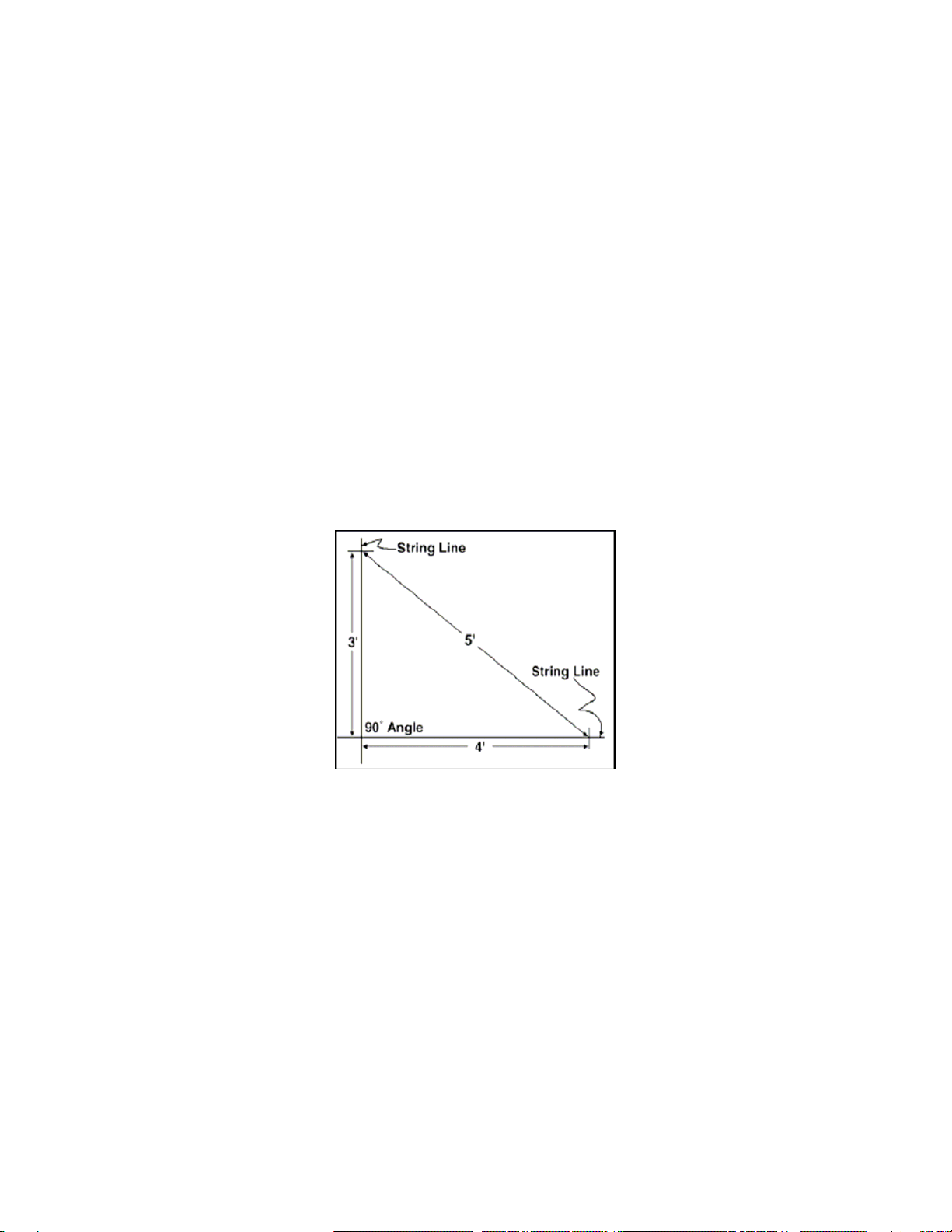
• The site must be level to properly and safely erect and anchor the structure.
• If the site is not level, use footings to provide a secure base for the structure. Pre-cast concrete
blocks, pressure-treated wood posts, or poured footings are all acceptable when properly
used.
• Drainage: Water draining off the structure and from areas surrounding the site must drain away
from the site to prevent damage to the site, the structure, and contents of the structure.
ATTENTION: The individuals assembling this structure are responsible for designing and furnishing
all temporary bracing, shoring and support needed during the assembly process. For safety reasons,
those who are not familiar with recognized construction methods and techniques must seek the help
of a qualified contractor.
Unpack and Identify the Parts
The following steps will ensure that you have all the necessary parts before you assemble the
structure.
1. Unpack the contents of the box and place them where you can easily inventory the shipment.
Refer to the Bill of Material.
2. Verify that all parts listed on the Bill of Material are present. If anything is missing, contact
customer service.
NOTE: At this time, you do not need to open the plastic bags containing the fasteners.
Visit www.ClearSpan.com for additional products and customer assistance.
2 of 36

166P0XX
1.66” XX” PIPE
PLAIN
QH1061
1” x 4000-LB. RATCHET
QH1065
2” RATCHET
FALB08B
1/2”-13 NUT - ZINC
FALB04B
3/8”-16 NUT - ZINC
FA4482
#14 x 1” TEK SCREW
PART IDENTIFICATION
(All parts are not shown)
166S099
1.66” 99” PIPE
SWAGED
42R3501D
PIPE 3.50” DRILLED
RAFTER POSITION 1
42R3502
PIPE 3.50”
RAFTER POSITION 3
42R3501
PIPE 3.50”
RAFTER POSITION 2
105118
4’ STRUT
105242
3.50” PIPE FITTING W/BASE
(See diagram on next page.)
105350
PURLIN
CONNECTION
BRACKET
105353
3’ STRUT
(3' rafter spacing only.)
105350 Bracket
X's represent length
needed to reach the end
of the building.
Visit www.ClearSpan.com for additional products and customer assistance.
3 of 36

100441
3/8” NUT SETTER
104189
TURNBUCKLE ½” X 6”JAW/JAW
GALVANIZED
AR1050
GALVANIZED
CABLE 3/16”
AS1003
3/16” CABLE CLAMP
AS1083
3/16” CABLE THIMBLE
The rafter foot for each rafter leg must be assembled before it can be attached to the rafter. Use the following
diagram and information when assembling each rafter foot.
FAG355
HEX CAP 3/8”X 1”
104188
1/2” x 5 1/2” HEX CAP
BOLT
105370
1/2” x 4 1/2” HEX CAP
BOLT
LJ7510
DUCT TAPE
Rafter Foot Assembly
105092
Pipe
105371
Carriage
Bolt
105241
Base
FAMA40
Lock
Washer
FALB08B
Nut
ATTENTION: Assemble as
shown, but do not tighten the
mounting bolt at this time.
Visit www.ClearSpan.com for additional products and customer assistance.
4 of 36

Frame Assembly Diagram
(Frame shown may be shorter than actual frame.)
End Rafter: Rafter A
Purlin
Purlin
Customer-Supplied
Baseboard
Interior Rafters: Rafter B Cable Assemblies
Customer-Supplied
Baseboard
Frame End View:
Purlin Locations
Visit www.ClearSpan.com for additional products and customer assistance.
5 of 36

Side View of Rafter Assembly
Diagram above shows the 4' on-center rafter spacing.
Center-to-Center
Rafter Width: 42' Center-to-Center
Purlin
Custom-Supplied
Baseboard
End View of Rafter
Visit www.ClearSpan.com for additional products and customer assistance.
6 of 36

Layout the Building Site
After the site is prepared, marking the ground where the building will be situated and identifying
where the corners of the building will be placed helps square the frame after it has been assembled.
Taking these steps before assembling the building saves time and ensures that the structure is
positioned as desired. The following procedure is a suggested method. Its use depends on the size of
the building, its application, the footings, and the method used to anchor the building.
Square the Site
1. Identify a corner where a building rafter will be positioned, drive in a stake, and string a line the
exact width of the building and stake in place. (Width of the rafter is measured from center-to-
center of the rafter legs.)
2. String a line at least as long as the building from the first stake at 90°.
NOTE: A transit can be used to ensure an accurate 90°angle, or the 3-4-5 rule can be used. See
the diagram below. Using multiples of 3-4-5 such as 6-8-10 or 12-16-20 helps to maintain an
accurate 90°angle.
3. After squaring the position of the building and placing a stake at all corners, string a line between
the stakes to outline the base of the building.
4. Next, paint a line on the ground using the strings between the stakes as guides.
NOTE: There is no need to mark the rafter spacing. The purlins, when installed correctly, will
maintain even rafter spacing throughout the length of the shelter.
5. After marking the outline of the building, remove the strings and continue with the rafter and
framework assembly instructions for the building.
Visit www.ClearSpan.com for additional products and customer assistance.
7 of 36

Rafter Introduction
All rafters consist of the following five (5) pipes: 2 (42R3501D), 2 (42R3501), and 1 (42R3502). The
two 42R3501D pipes include two drilled holes near the bottom to connect the rafter foot.
Assemble Rafter A (There are two (2) end rafters.)
1. Connect the pipes as shown in Diagram A below.
2. Assemble rafter on the ground; slide swaged section into plain section until 9/16” holes line up
(Figure 1). Secure each pipe joint with one ½" x 5½" bolt and a single Purlin Connection Bracket
(Figure 2).
3. Insert one rafter foot (105242) into the bottom of the rafter and secure with (1) one ½" x 5½" bolt
and a single Purlin Connection Bracket in hole furthest from foot base. In hole closest to foot
base, secure foot to rafter using ½" x 4½" bolt (Figure 3).
4. Repeat Step 3 for the remaining rafter foot.
5. Repeat the above steps to assemble a second Rafter A.
ATTENTION: Install all brackets and bolts so they do not interfere with the installation of the main cover. To protect the
cover, tape all rafter joints with duct tape.
Diagram A
Figure 2
Figure 1
Figure 3
42R3501D
42R3501
42R3502
Arrow points
to the inside
of the shelter.
Position
p
urlin bracket to the inside of the shelter.
Duct Tape here
Visit www.ClearSpan.com for additional products and customer assistance.
8 of 36

Assemble Rafter B (Interior rafters)
NOTE: The length of the shelter and the on-center spacing of the rafters determine the number of
interior rafters. Locate the All Frame Diagrams near the end of these instructions to view the frame of
your shelter.
1. Connect the rafter pipes as shown in Diagram B below.
2. Assemble rafter on the ground; slide swaged section into plain section until the 9/16” holes line up
(Figure 4). Secure each pipe joint with one ½" x 5½" bolt and two (2) Purlin Connection Brackets
(Figure 5).
3. Insert one rafter foot (105242) into the bottom of the rafter and secure with (1) one ½" x 5½" bolt
and two (2) purlin connection brackets in hole furthest from foot base. In hole closest to foot base,
secure foot to rafter using ½" x 4 ½" bolt (Figure 6).
4. Repeat Step 3 for the remaining rafter foot.
5. Complete this entire procedure to assemble remaining interior rafters (Rafter B).
ATTENTION: Install all brackets and bolts so they do not interfere with the installation of the main cover. To protect the
cover, tape all rafter joints with duct tape.
42R3501D
42R3501
42R3502
Diagram B
Figure 4
Figure 6
Figure 5
NOTE: For longer shelters, assemble and place
the interior rafters in an accessible position that
will not interfere with the frame assembly.
105350
Duct tape here
105370
104188
104188
Visit www.ClearSpan.com for additional products and customer assistance.
9 of 36

Frame Assembly: Standing the End Rafters
After all rafters are constructed and placed in an orderly fashion for frame assembly, proceed with
standing the first end rafter. Forklifts and personnel booms are recommended for lifting and setting
the rafters. Consult a construction professional if you are not familiar with construction techniques and
erecting similar structures.
Stand and Secure the First End Rafter
ATTENTION: Use the proper lifts. Rafter assemblies are heavy and awkward to handle.
1. Stand the first end rafter (Rafter A) and secure it using rope, cable, or some other form of bracing
to hold the rafter in position. Use a level (or other leveling device) to plumb the end rafter.
NOTE: Plumbing the end rafter at this stage assists in placing the remaining rafters.
2. Secure the rafter feet to the site (or customer-supplied baseboards) to prevent the rafter from
shifting.
NOTE: The use of a baseboard beneath the feet of the rafters is strongly recommended. The feet
then can be secured to the baseboard using customer-supplied lag screws. Baseboard can be treated or
plastic lumber. Contact Customer Service at 1-800-245-9881 for additional information.
Temporary bracing
used to secure the
end rafter in place.
Rope or Cable
Visit www.ClearSpan.com for additional products and customer assistance.
10 of 36

Frame Assembly (continued)
With the first end rafter standing, plumb, and properly secured, set the interior rafters in place.
Stand the Interior Rafters
1. Stand the second rafter (Rafter B) and secure the rafter feet as before.
2. While the lift or personnel are holding the rafter in position, start at the top-center of the arch and
install a purlin. Each purlin pipe is attached using 3/8" x 1" Hex Cap bolts provided. Use two (2)
bolts per connection point when attaching the purlins to the purlin clamps. (See insert below.)
3. With center purlin in position (arrow below), install the remaining purlins. There are six (6) purlins
between each rafter. Consult the Frame Diagram shown earlier in these instructions for purlin
location.
4. Repeat the process for the remaining interior rafters for the length of your building. (Align the rafter
feet with the lines previously marked on the site if that method was used.)
5. After all interior rafters are in place and secure, install the final end rafter (Rafter A).
6. With all rafters in place, read the MUST READ document to anchor the frame. You must anchor
the assembled frame before continuing.
7. After anchoring the frame, continue by installing the cabling for the structure.
ATTENTION: As the purlins are attached, it may be necessary to tap the purlin brackets with a hammer to align the
brackets with same brackets on the next rafter set in place. To protect the cover, tape all rafter joints with duct tape.
Purlins (105118) are
interchangeable.
View from the top looking down on
the rafter, purlin clamps, and purlins.
Attach this purlin first.
Visit www.ClearSpan.com for additional products and customer assistance.
11 of 36

Cable Assemblies
Cable assemblies provide diagonal bracing for the building. Each cable assembly includes the following items:
• 2 lengths of cable cut at 100"
• 1 turnbuckle
• 4 cable thimbles
• 4 cable clamps
Typical of all Turnbuckles for this Building
NOTE: For each cable assembly, two (2) additional thimbles and four (4) additional cable clamps are used to
attach the cable assembly to the purlin clamps. Consult the Cable Diagram on the following page and the All
Frame Diagram for clarification and cable locations.
Cable Assembly Instructions
Complete the following steps:
1. Cut the cable to the proper length for each assembly. More than an adequate amount has been sent for the
cabling application. (Cut two lengths at 100" and make a single assembly before proceeding to make all.
This will allow a check to be sure a suitable length has been cut.) Make the necessary length adjustment if
needed.
2. Place one cable thimble approximately 12" from the end of a cable section and wrap the cable around the
thimble as shown in the above figure.
3. Grasp both sections of the cable near the thimble and position one cable clamp one inch away from the
thimble as shown above.
NOTE: The clamp must be positioned on the cable with its U-bolt portion over the short section of the cable.
4. With the saddle portion of the cable clamp in position, thread the nuts onto the U-bolt section of the clamp
and tighten slightly to maintain the position of the clamp on the cable.
5. Install a second cable clamp on the cable six to eight inches from the first clamp.
6. Tighten both clamps.
7. Remove the bolt from the jaw of the turnbuckle and position the cable end with the thimble into the jaw of
the turnbuckle.
Turnbuckle Turnbuckle Jaw
Thimble
Cable
Cable Clamps Thimble
Visit www.ClearSpan.com for additional products and customer assistance.
12 of 36

8. Insert the bolt through the eye of the turnbuckle and the cable thimble, thread the nut onto the bolt, and
tighten.
9. Repeat Steps 2-8 for the remaining length of cable for this assembly.
10. Open the turnbuckle to its longest position.
11. Repeat the above procedure for all remaining cable assemblies.
Cable Placement
The diagram and figures below identify the placement and proper way to attach the cable assemblies to the
building.
Cable Placement Diagram
To protect the cables,
position thimbles as
shown in the diagrams.
View above is from inside the shelter.
Customer-Supplied
Baseboard
Visit www.ClearSpan.com for additional products and customer assistance.
13 of 36

Tighten the Cabling
The positions of the cable assemblies are identical for the opposite side and the remaining end of the building
that are not shown in the previous diagram. For cable locations for your building, consult the All Frame
Diagram.
1. After attaching all cable assemblies to the building frame, return to the first set of turnbuckles and tighten
the cables.
NOTE: Tighten the cables in each section evenly so that the frame remains plumb.
2. After one set of cables is tightened, move to another set and repeat the tightening steps.
3. Repeat this process until all cables are tight.
4. Continue with installing the ratchets for the main cover.
Install the Ratchets for the Main Cover
The side ratchets are attached to the legs of select rafters on the outside of the rafter leg. Complete the
following steps to position and secure the ratchets to the rafter legs.
NOTE: The four (4) QH1061 ratchets used to secure the bonnet of the main cover are attached to the bottom
frame tube of the end wall after the end wall and end panel are installed. Install only the larger QH1065
ratchets to the rafter legs along the side at this time. The steps are described below.
1. At each leg of each end rafter, attach one QH1065 ratchet on the outside of the rafter leg in the location
shown above.
QH1065
Customer-Supplied Baseboard
Purlin
End Rafter
Rafter Foot
Visit www.ClearSpan.com for additional products and customer assistance.
14 of 36

2. Select the remaining QH1065 ratchets and evenly space these along each side of the frame. The following
is an example of where to attach the remaining ratchets.
NOTE: Depending on the length of your structure, you may not be able to install the ratchets on every other
rafter as shown above. The main point is to space the ratchets as evenly as possible so you can stretch and
secure the main cover. See the example below. Frame shown may be shorter than your frame.
3. After all side ratchets are installed, continue with the end wall and panel installation procedures.
Location of QH1065 Ratchets
along one side of a frame
assembly.
Customer-Supplied Baseboard
Visit www.ClearSpan.com for additional products and customer assistance.
15 of 36

END WALL INSTALLATION
Both end walls are identical in design. This allows for the installation of a second door kit if desired. Consult the end wall
diagrams before you begin.
The general steps to install the end walls include the following:
1. Prepare and secure vertical posts for the door framing. (See End Wall Diagrams.)
2. Install remainder of door framing.
3. Assemble and attach all end wall framing.
4. Prepare and attach end panel.
INSTALL THE DOOR FRAME
1. At ground level, measure between the legs of the end rafter to locate the center of the end wall. Use a plumb line to
identify the center of the overhead rafter and mark that location on the ground, too.
NOTE: Mark the center of the end wall so multiple measurements can be made from it.
2. Using the dimensions shown on the diagram, locate the positions of the vertical frame members for the door framing.
3. Dig a 12” diameter hole at the locations found in previous step to a depth that is below the geographic frost line.
4. Assemble the vertical doorframe members and attach the upper ends to the end rafter. ATTENTION: Cut each tube
to a length that will allow the bottom end to extend into the ground anchor holes so they can be cemented in place.
5. After the vertical doorframe members are in position, plumb, and the correct distance apart, secure the tubes in the
ground holes. Use the diagram to space the vertical doorframe members.
NOTE: Concrete should remain at least 4" below ground level so that it does not interfere with construction and
installation of other end wall components. Doorframe tubes must be square and plumb for the end wall.
Vertical Doorframe tube:
4” Square Frame Tube
encased in concrete
Ground Level
Section of the
assembled End
Wall Frame.
Concrete
Visit www.ClearSpan.com for additional products and customer assistance.
16 of 36

ASSEMBLE THE END WALL FRAME
After the doorframe is assembled and anchored in place, assemble the remainder of the end wall.*
NOTE: Tek screws are used to fasten the following connectors:
• QH1330 Angle Bracket
• 104624 Square Tube Fitting
• 104075 1.75” x 1.75" Square Tube Connector
The 5" carriage bolts (105348) are used to secure the following brackets:
• 105351 4" Mounting Bracket
• 105243 Mounting Plate
*Refer to the End Wall Diagrams for locations of additional pedestrian door framing and connecting hardware.
Complete the following steps:
1. Using the dimensions on the End Wall Frame diagrams and the 2" x 2" square tubing and related hardware and
connectors, assemble the remainder of the end wall.
2. Consult the Exploded End Frame Diagram to properly position and connect the brackets.
NOTE: The end wall framing on either side of the large door opening is the same.
3. Repeat the steps to assemble the end wall framing for the remaining end of the building.
4. Attach the ends of the bottom end wall frame tube as shown in the following diagram.
5. After both end walls are assembled, continue with the End Panel Installation procedure that follows.
If a baseboard was not used
when the building was erected,
the bottom frame member must
be anchored using alternative
methods.
Consult a professional building
contractor if needed.
Bottom Frame Member
QH1330 Bracket
Customer-Supplied Baseboard
Rafter
Visit www.ClearSpan.com for additional products and customer assistance.
17 of 36

END PANEL INSTALLATION
Complete these steps to install the end panel.
1. Position the panel flat on ground with the long edge against the bottom end wall frame member.
2. Locate the D-Rings, which line the top of the end panel, and insert a three-foot piece of black strapping into the center
most D-Ring. Insert 2 additional straps on each side of the center D-Ring if needed. (Space these at every other D-
Ring.)
NOTE: These straps are used to temporarily secure the end panel in place. Add more strapping if needed. To prevent
personal injury or property damage, do not install end panel or main cover during stormy or windy conditions.
3. With the black strapping in place, raise the end panel to the end wall and secure to the end rafter using the D-Rings
and strapping.
NOTE: Pull the top edge of the end panel to within 6" of the rafter. (Approximately 1 to 2 feet of the end panel material
will remain at and run along the base of the end wall. In a later step, this can be wrapped under the bottom tube of the
end wall frame, or remain as a skirt to direct water away from the shelter.)
The end panel must touch the ground after the top edge of the panel is secured to the rafter.
View is from the inside of the shelter looking at the end panel. Frame and rafter shown are different from your frame.
The technique used to secure the end panel is the same however. Photo shows the main cover already installed.
Strap in D-Ring
Rafter
End Panel
Main Cover
Vertical Frame Tube
for the End Wall
Visit www.ClearSpan.com for additional products and customer assistance.
18 of 36

4. Once the end panel is temporarily secured, take the roll of black strapping and weave the end of the strap through the
D-Rings and around the rafter pipe as shown below.
NOTE: Maintain an even space between the rafter and the top of the end panel. The end panel flap that extends
beyond the D-Rings is tucked between the rafter and the main cover after the main cover is laced to the end rafter.
DO NOT attach the flap to the end rafter at this time.
Photo above shows a building with the main cover already installed. View is from the inside looking up at the rafter
and main cover.
5. Stretch the bottom of the end panel evenly out on the ground along the bottom frame tube of the end wall frame (if
needed) and tighten the black strap at the top of the end panel. Top of end panel must remain as close to the rafter as
possible.
NOTE: Verify that the lower end of the panel remains on the ground as the top is tightened. If the panel begins to lift
off the ground, loosen the top evenly along the radius of the rafter. (In a later step, the end panel is stretched from the
bottom to pull the panel tight and into position using the end panel horizontal conduit, straps, and ratchets.)
6. With the top edge of the end panel secured, continue by cutting the opening for the door (or doors). If you are
installing an end panel and no door openings are needed, skip to and continue with the End Panel Conduit Installation
steps.
Strap with built
in D-Rings at the
top edge of end
panel
Main security strap woven
through D-Rings and around
the end rafter.
End Panel
Main Cover
Visit www.ClearSpan.com for additional products and customer assistance.
19 of 36
This manual suits for next models
3
Table of contents
Other ClearSpan Storage manuals