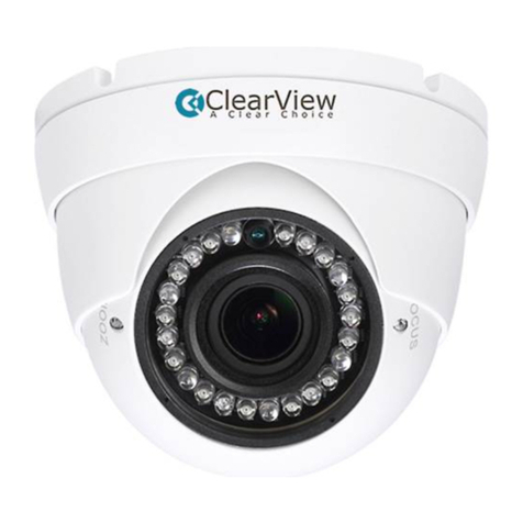
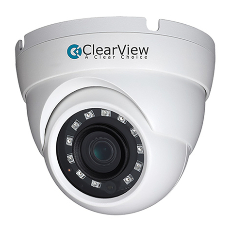
ClearView CA-0581 BP/N User manual

Analog Camera
- --
-.-·--··
·-
·-
·
···
···
·
-··
·--
·-·
-
·-········-···-
··
··-·
·
·--·-
...
/ User's Manual(
K)
\
z··-
·
----
·
····-·-
··
·····-
··
·---·
..
·-~--
·
··
..
··-···--·-·-····
·
..
.....
--~~--,..,·_,,.,
,
,
,
,-,_.
_
,.,.-
-.-
.
'':'
?'·
·
-":-c""'-'""
" '>;'
-',.,;"
,..,
~
...
~
.
..,
.
.,.
.""".
,
"'.-,.,-
1""
,.
,
-
c
,"
'"
'
.:f
{l!.~
Version 1.0.0

!I
, I
i l
i i
::
Welcome
Thank you for purchasing our analog camera!
::
This
user's
manual
is
designed to be a reference tool for your system.
~ ~
; I
~
:
I
i
~
i l
i!
H
I'
I'
!l
I I,
Please read the following safeguard and warnings carefully before you
use this series product!
Please keep this
user's
manual well for future reference!
...
..
.
..
.
..
-
..
.
..
..
.···
··
--..
...
...
...
.
..
._
... " ...
...
.."'
..
..
..
' • " -.
...
..
...
....
..
"..
. .--------...
..
.
..
.
..
.
...
..
..
'"
...
..
..
..
..........
·----
-
---
···
·--
·-
·
-·--
·-..
........
..
..
·-··--
--
.
..
.
..
.........
..
"· "
...
..
..
.
..
..
..
.....
......
....
I'
•'
I '
, .
• '
;I
,.
;;
,,
·
,r
; I
i (
/!
·-
-
-
~
··
·
-
'./
...,<·
-
~
-
~
~
-
~
-
'·
-~··---
~
----
~
-
.
....
..
..
.
~-
-
-
-
·
-
..
- .
..........
..
.
..
. .
.....
~
--
....
.
...
. . . - .
..
. .
..
. .
..
.
..
.
..
.
...
.. • • • • •
..
. .
..
....
.
....
...
..
. . .. .
..
...
. . . .
..
.
..
. .
..
..
.
..
.
..
. .. . .
..
.
....
.
..
..
..
.
..
.
....
• . .
...
.
..
.
..
..
.
..
. .
......
. . .
...
. . . -
..
.....
...
..
. .
..
...
. .
....
_ . .
..
.
..
.
..
.
..
.,
..
.
..
.
......
. .
..
..
.
..
..
. . .
..
.
..
. .
..
....
..
. - - -- - ·- · · -
···
·
··
· · · · · ·
····
·
""
" · · · ·
--
, .
....
..
..
. h . . . . .
..
. . . .
.....
. . .
•'
• I
Important
Saf.eguards
and
Warnings
1.
Electrical safety
All installation and operation here should conform
to
your local electrical
safety codes.
!!
1[
, i ll
::
The power shall conform to the requirement
in
the
SELV
(Safety Extra
::
;;
H
::
Low Voltage) and the Limited power source
is
rated 12V DC or 24V AC
i!
:
~
H
ii
in
the IEC60950-1. ;;
;:
~
i
i l
;i
!i
; I
::
We
assume no liability or responsibility for all the fires or electrical shock !i
ii
;l
II
caused by improper handling or installation. i!
i;
j l
ii
2.
Transportation security
!!
H
!!
i!
Heavy stress, violent vibration or water splash are not allowed during
!!
li
q
li
transportation, storage and installation.
li
n
l!
ii
3.
Installation
!i
rt
!
~
!I
ll
n Do not apply power to the camera before completing installation.
!i
H :;
ii
Please install the proper power
cut-off
device during the installation
ii
n
~ ~
ii
connection.
!!
.,
H
!i
Always follow the instruction guide the manufacturer recommended. ii
ll
I'
ii
If this product
is
installed
in
the ceiling, please make sure the installation il
li
position can sustain the min
SON.
!!
i
~
p
n n
'<"
':
..
..
~:
:
~~::;:
:
::::
:
::
:
:
~~:
::
:
:
::
:
:::~~:::-::::::::
::
:::-
.~
:::::::::
~~.-
:.~::::::::::·"
_
:
:~
.~::~.::
:
:
:
::~
::
:
~
~-~::.
~:~.:.:::
:
~
.
.-:::;::
:
::
:
:::
~
;:::::-
.
:
:::
:::~~
-
:
·
..
:..
::-.
:
.
::.
:::::
~h
:
:::-.
:::
:
::::
::
.:~
~
.-
::
:
::::::::~:~-:::::::::::
:
~-:::
:
:
.
..:::::.:::
:
:::
·
.:
:
.
:
.:
:
:
:~
::.
:
::.
::
:
:
:~~:
.
:::
:
:
::
~
:
::.:::
:
:
:·:
·.:
::::.:::
:
::::-~~~~:
~
:
:::·
:
.
:
:
: :::
::
::
:
:::::
:
::::-
.:
:
:
~
"-
::.
::~
:
:
:::::::::::~-:
::
::
:
:~
:
:.·:~/
User's Manual ( K )
01

...
·-·
~
·•·
..
Anal9g
9a~~r?
.
....
·
lmporta·nt
Safeguards
and
Warnings
' '
1'
J•l
I 1 / I 1 I I 1 , I I
,.
i ;
..
'
4.
Qualified engineers needed
All the examination and repair work should be done by the qualified
service engineers.
We
are not liable for any problems caused by unauthorized modifications
or attempted repair.
5.
Environment
This series analog camera should
be
installed in a cool,
dry
place
away from direct sunlight or
strong
light,
inflammable,
explosive
substances and etc.
The working temperature ranges from -300C to
+600C.
Please keep
it away from the electromagnetic radiation object and environment.
Please make sure the CCD component
is
out of the radiation of the laser
; ,
•
,:
,.
"
"
"
, .,
;,
,,
! '
~
;
,.
;;
"
,,
"
il
"
,,
! I
;;
, :
,.
,,
,,
. ;
beam device. Otherwise
it
may result
in
CCD optical component damage. ;;
·,
;
·,
, ,
"
; :
,.
i i
,,
:;
~
i
~
j
;;
H
1:
H
!!
i !
:i
Please keep the sound ventilation.
Do not allow the water and other liquid falling into the camera.
6. Accessories
Be sure to use all the accessories recommended by manufacturer.
Before installation, please
open
the
package
and
check
all the
components are included.
Contact your local retailer
ASAP
if something
is
broken
in
your package.
7.
Daily Maintenance
Please shut down the device and then unplug the power cable before
you begin daily maintenance work.
, ;
"
;;
il
"
H
:;
II
~
:
.,
"
"
q
i l
:
~
!'
{I
i
~
; I
,.
"
) !
/I
q
d
i !
"! j
;:
; I
I I
,,
;
~
/ i
I !
:
~
Do not touch the CCD optic component.
You
can use the blower to clean !!
~
~
the dust
on
the lens surface.
Always use the dry soft cloth to clean the device. If there
is
too much
dust, please use the water to dilute the mild detergent first and then
use it to clean the device. Finally use the dry cloth to clean the device.
Please put the dustproof cap to protect the CCD component when you
do
not use the camera.
n
··
,_
---
-···
··
--·-----
--
--
·-•
""""'
""
"'
"•"'"'
""
..
.
..
..
..
,
..
..
.........
--
..
..
..
-
..
..
..
.
..
.--
...
....
..
. .
..
.
......
-
......
--
..
..
.....
......
..
...
.
...
...
.
..
.
..
.
....
.
..
,..
..
.
.......
..
........
...,
..
.-
..
..
..
-,.
.-
..
,.
..
..
..
-..-.
..
.
....
..
.
..
..
..
..
...
..
...
..
..
.
..
.....
..
..
..
.
..
.
..
.
..
..
.
..
----
-----
--
---
..
.....
....
.
..
...
---
---
--
-
--
--
...
.
..
.
..
...
.
..
..
..
__
..
___
----
-
----
·-.
..
..
..
.....
..
...
..
-
.
--
-
-
-
-
~
----
·
-
.·
-
-
--
-
-
..
,._/
Analog
Camera
--
----
--
--
---
--
--
--------
02
User's Manuai(K) :
., .
,.
__
__
_
__
___;___
___
___
__
__
____________
---
- -
--
--
..
- - ·-
---
---
--
- -- -
-·-··
-------- ....
-------
--·
-··-
--
---
J
'''
,,/,
''
I '
,
r'
I
''
' '
I '
f
I
1 , I
Table
ot Contents· ··
' I
/f
,
,
1 Generallntroduction
...................................................................
05
1.1 Overview.................
..
...
..
................
..
...........................................
..
.
..
..
...
...
05
1.2 Features...
..
..
..
............
....
..
..
..
...
.
...
..
..
.. ..
..
.....................
...
..................
..
......
..
05
1.3 Functions
..
..
.........
.. ..
.........
.
..
.
...
....
..
..
...
...
........
..
...
...
...
...
.
..
...
....
...
...
.
....
...
..
...
05
1.4 Specifications
....
.........
...
..
......
............
.. ..
.......
.. .. ..
.............
..
.
..
.
..
.
..
..........
...
07
1.4.1 700 TVL ICR Day/Night WDR Dome Camera
..
....
..
...
..
..
......
..
....
...
..
.
07
1.4.2 700 TVL ICR Day/Night
WDR
Vandal Proof Dome Camera
..
.....
.. ..
.
08
2
Framework
...................................................................................10
2.1
Dimensions.
...
..
...........
..
................
...
.
..
.
....
.
..
.
..
..
..
.......
...
.
...
.........
..
...
.......
..
..
10
2.1.1 700 TVL ICR Day/Night
WDR
Dome Camera......
..
..
........
...
..
.
..
..
..
.
..
1
0
2.1
.2 700 TVL ICR Day/Night
WDR
Vandal Proof Dome Camera
..
....
..
..
..
1
0
2.2 Structure
..
.
..
.
...
........
..
....
..
.
..
.
..
..............
...
..
........
..
.....
..
.
..
.....
..
.
..
.....
..
.......
...
.
11
3 lnstallation...................................................................................12
3.1
700 TVL ICR Day/Night WDR Dome Camera Installation.....
..
......
..
.....
..
..
12
3.2 700 TVL ICR Day/Night WDR Vandal Proof Dome Camera Installation..
16
4 Menu.............................................................................................
20
4.1
Main Menu
...
.........................
..
...
..
...
..
...
...
.......
...
...............
...
..............
..
.
...
.
20
4.2 Main Interface
..........
..
.
...
.....
..
.................
...
..
..
..
....................
..
..................23
4.3 Detailed Operation...............................................
..
...........
..
..
.
..
...
....
.. ..
..
..23
4.3.1 LE
NS
......
...
........
...
..
.
...
..
..........
...
.......
..
..
.......
..
.......
..
......................
...
24
4.3.2 SHUTIER GAIN.
...
..........
...
..
..............
..
.
..
.
...
.............
..
...
...................24
4.3.3 PICTURE ADJUST
..
...
..
..
...
...
.
..
......
..
...
..
.......
..
..
.
..
...........
..
.....
..
..
.
..
..
...
25
User's
Manual
(
K)
03

4.3.4 WHITE BALANCE (WB)..............................................
..
...........................26
4.3.5 WDR.
...
..
...............
...
.
..
..
.............
..
......
...
..
.
..
.........................................
..
....27
4.3.6 NR (NOISE REDUCE/DE-NOISE)
..
..
......................
..
...........
..
..................27
4.3.7 HLC/BLC............................
...
..
...
...
..............
...
.........................................27
4.3.8 DAY/NIGHT
...............................
...
..
...
..
.
...
.. ..
.
...
..
........
..
.............
..
.
...
.......
..
28
4.3.9 DIGITAL ZOOM..........
..
............
..
.
..
............
...
.................
..
..................
..
.
...
29
4.3.10 PRIVACY MASK
........................................
..
..
.........................................
29
4.3.
11
MOTION DETECT
...... ..
...
.....................................
..
...............................
30
4.3.12 SYNC MODE...........................
...
..
...........
..
...
.....................
..
..
..........
..
....
30
4.3.13 CAMERA ID
.................................................................................
..
......
..
31
4.3.14 LANGUAGE............
...
.............
....
..............
...
.
...
..
......
..
...
.......
..
...
....
..
.......
31
4.3.15 CAMERA RESET.....................
..
...............................................
..
.
..
....
...
..
31
4.3.16 OTHERS
......
...
.
..
............
...
.......
..
.
....
....
..
...
......
..
...
..
.
..
............
...
................
31
Appendix Toxic or Hazardous Materials or Elements
.................
32
~~~'
-
0.9
.
~~
-
1'!1
-
~
~~
-
04

User's
Manuai(K) l
~
·
~-
---
···
··
-
---
··---
·-
--
··-.
-
--
-·
···--
·-
-
---
--
·
---
--'
General Introduction
1.1
Overview
This series analog camera adopts the high sensitivity CCD and advanced circuit
design. It
is
featuring the high quality video, the lowest distortion, low noise and
etc. This series product
is
suitable to be used
in
surveillance system and video
process system.
1.2 Features
• Support
75d8
WDR
range suitable for the surveillance
in
the backlight
environments.
• Clear video, over 700 TVL resolution.
• Support
WDR,
high light compensation (HLC), backlight compensation
(BLC) and etc.
• Support
20
and
30
de-noise.
High signal to noise ratio (SNR), clear and
impressive video.
• Support advanced applications such as digital zoom, digital image
stabilization, privacy mask, and motion detect.
• Support OSD
(on-screen
display), suitable for user self-defined setup.
• Support auto white balance function. Restore high definition and more vivid
video.
1.3 Functions
High Definition
700
TVL
540TVL
700TVL
User's
Manua
l ( K )
05

Analog Camera
__
_
WDR
When there is strong light, shadowand backlight all
in
one surveillance environment,
the camera output video may become white owning to the extra exposure while
some sections become black owning to the insufficient exposure. All
of
these
will adversely affect the video quality.
WDR
is to balance the light between these
two sections.
You can
compare
the following two figures.
..
General Camera WDR Camera
Low
illumination
The system can output the proper video even in dark environment.
General Camera Low Illumination Camera
Ana'og
Camera
06

1.4 Specifications
1.4.1 700 TVL ICR Day
/Night
WDR Dome Camera
Please refer to the following sheet for specification.
CA-0581BP/N(-A)
Video Processor 1/3" SONY Super HAD CCD
II
Video Format PALINTSC
PAL 976
(H)
x 582 ( V ) 570K pixels
Effective Pixel NTSC 976
(H)
x 494 ( V ) 480K pixels
Resolution
?OOTVL
WDR Range
75dB
Color: 0.005Lux
I
F1.4, 0.0005
lux@
(F1.2 slow shutter
*512)
Min Illumination Black and white: 0.0005Lux
I
F1.4, 0.000051ux@
( F1.2 slow shutter
*512)
Auto:1/50s-1/1
OO,OOOs
,10s-1/100,000s @(Slow
PAL shutter *512)
Manual: 1/50s,1/120s,1/250s,1/500,1/1000s,
1/2000s,1/4000s,1/10,000s
Electronic Shutter Auto:
1/60s-1/100,000s,
8s-1/100
,000s@(slow
NTSC shutter *512 )
Manual: 1/60s,1/100s,1/250s,1/500,1/1000s,
1/2000s,1/4000s,1/10,000s
Lens Type Default model is
cp
14 port 4.
0-9.0inm
ICR zoom auto
aperture lens
(2.8-
12mm)
Video Output
1Vp-p
Composite Output (
750hm/BNC)
SNR Above 60dB
OSD Menu Control Support
LENS Auto/Manual
SHUTIER/AGC Auto/Manual
PICTURE ADJUST Mirror/contrast/sharpness/hue/gain/slow shutter
WHITE BALANCE Push/user 1/user 2
I
ANTI
CR
/manual/push lock/ATW
Menu NR Low, midlow ,mid, midhigh, high, off
HLC/BLC BLC/Level/scale/HLC
DAY/NIGHT MODE Auto/black and white/color
DZOOM Magnitude/pan/tilt
User's Manual (
K)
07

r-
-·.
·~~
.
~--
·
·
·
~
·~
~
·
'
~
-
·
~·
""
•·
··-
·
-
· ·
..
-
.....
. ·····
--·---
.
....
....
.
...
.
L
..
...
..
~D~!c:>g
_
g~
_
'!l~f.9
__..
DIS On/off
PRIVACY MASK Area selection/mode/position/color/transparent/mosaic
MOTION DETECT Detect sensitivity/block display/monitor area /area selection
Menu
Sync
Mode
INT
Camera
ID Character/position
Language
English/Chinese
Working Temperature
-30"C
-+60"C
Power DC12V ± 10%
(
-A
) series
product
support AC24V ± 10% /DC12V± 10%
Power
Consumption
3.
5W
Max
Dimension (mm)
cp
140.8
X
120
Weight
400g
(
-A:
450g )
1.4.2 700 TVL ICR Day/Night WDR Vandal Proof Dome Camera
Please refer to the following sheet for specification.
CA-08581BP/N{-A)
Video Processor 1
/3" SONY Super HAD
CCD
II
Video Format PAUNTSC
PAL 976
(H)
x 582 (
V)
570K pixels
Effective Pixel NTSC 976
(H)
x 494 ( V )
480K
pixels
Resolution 700TVL
WDR
75dB
Color:
0.005Lux I F1.4. 0.0005
lux@
(F1.2 slow shutter
*512)
Min Illumination
Black
and white: 0.0005Lux I F1.4, 0.00005 lux@
( F1.2 slow shutter *512 )
Auto:1/50s-1/1
OO,OOOs,
10s-1/100
,000s @(Slow
PAL shutter *512)
Manual: 1/50s,1/120s,1/250s,1/500,1/1000s,
1/2000s,1/4000s,1/10,000s
Electronic Shutter Auto:
1/60s-1/1
OO,OOOs,Bs
-
1/1
OO,OOOs@(slow
NTSC shutter *512 )
Manual: 1/60s,
1/1
OOs
,1/250s,1/500,1/1
OOOs
,
1/2000s,1/4000s,1/10,000s
Ana
log
Camer
a
--·
-·-
---·
-·--
·-
----
--
-
08

User's Manuai(K) :
=:=========c
,_
__,___
__
__..__.
__
____.,_.__
..
,.
....
._
...
........
...
...
......
...
..
....
.,_ .
,
_
~
--
--
·--
·
·
-
·
·
-·
·-
"
·-·-
1
LensType Default model is
<P
14 port
4.0-9.0mm
zoom auto aperture
lens
(2.8-
12mm)
Video Output
1Vp-p
Composite Output (
750hm/BNC)
SNR Above 60dB
OSD Menu Control Support
LENS Auto/Manual
SHUTIER/AGC Auto/Manual
PICTURE ADJUST Mirror/contrast/sharpness/hue/gain/slow shutter
WHITE BALANCE Push/user 1/user 2 I ANTI
CR
/manual/push lock/ATW
NR Low, midlow ,mid, midhigh, high, off
HLC/BLC BLC/Level/scale/HLC
Menu DAY/NIGHT MODE Auto/black and white/color
DZOOM Magnitude/pan/tilt
DIS On/off
PRIVACY MASK Area selection/mode/pas
it
ion/color/transparent/mosaic
MOTION DETECT Detect sensitivity/block display/ Monitor area /area selection
Camera ID Character/position
Language English/Chinese
Working Temperature -30CC -
+60CC
DC12V ± 10%
Power
(-A)
series product support AC24V ± 10% /DC12V ± 10%
Power Consumption 3.5W Max
Dimension (mm)
<j>
160X 118.5
Weight 980g(
-A:
1
OOOg)
User's
Manual
(
K)
09

!
..
..
~
'
...
._
..
.
.....
.
....
.
~---
·-
~-
...
..
.,,
.,
_
...
..
..
..
-.. .
..
~
"
..
.
...
t-
.
11~!gg_g9
_
'!1~!:~
.
--
Framework
2.1
Dimensions
Please note all the units
in
the following figures are mm.
2.1.1 700 TVL ICR Day/Night WDR Dome Camera
Please refer to the following two figures for the dimension information. See
Figure
2-1
.
120mm
Figure
2-1
2.1.2 700 TVL ICR Day/Night WDR Vandal Proof Dome Camera
Please refer to the following figure for detailed information. See Figure
2-2.
~
.
f'!<i
_
l?9
.
t?.a!"'
_
~~~
-
10
.
.
...
: -
·~--·"
.
·-
.
.
...
-
;._
.
.._
-
~
.·
-'":
-
:
-
-.~
::·
·-:
¢160
~
-
--
'I
Figure
2-2

. .
.
..
~~er's
_
f\11anu~I(J()
.
2.2 Structure
Please refer to the following figure for detailed information. See Figure
2-3.
l
1
I
_,/
--·'
.----
·.J
....,.
.
---®
.
~
'(J~--;-
·"---.
. .
'i
.:
~s;.;.c;r
,__
®
-·<r.:
~cz,
700 TVL ICR Day/Night WDR
Dome
Camera 700 TVL ICR Day/Night WDR Vandal Proof
Dome
Camera
Figure
2-3
Please refer to the following sheet for detailed information.
SN Name
1
Device
lens
2 Dome
camera
side enclosure
3
X-
Y
-Z
rotation module
4 Dome
camera
external enclosure
5
Dome
camera
pedestal
6
Power
input
port. It
connects
to the DC 12V
power
to
input the power.
7
Video
output
port. It is the
BNC
port to output the analog video signal.
You
can
connect
to
the
devices
such as the DVR or the NVR.
User's
Manual
( K )
11

The dome camera usually mainly uses the in-ceiling installation.
Important
--1
~
Please
make
sure
the
installation
surface
can
min
support
the
3X
weight
of
the
camera
and
the
bracket.
3.1
700
TVL
ICR
Day
/Night
WDR
Dome
Camera
Installation
A
Mini
dome
pedestal
Installation
A1 Ex
pansion
bo
lt
A2Pedestal
secure
scr
ew
hole
A 3
Dome
Ca
mera
Pedestal
A4 Pedestal secure
scre
w
A_r:_c:lo9
Ca_m_!l
ra
12
AS
Celllng Or wall
Figure
3-1

8
Figure
3-2
C Mini dome component
\
Figure 3- 3
- -
·-
1
User's Manual(KJ 1
Pedestal cable
81
exithole
82 Side hole
B3 Pedestal secure
screwhole
U
ser
's Manual ( K )
13

0 Turn the camera
lens
to
the
proper
position
E
Dome camera external
enclosure and pedestal
Installation
Push
the
dome eamerJ
intern<:~!
enclosure
to
make
it
perfectly
fit
the
X-Y-Z
axis
rotation
module.
An
~
log
c:;a
m
e~a
14
Important
When you
turn
the
lens X-Y-Z axis.
pluse
m3e
sure you have
not
touch
the
lens.
which
may
re$Uit
in
th•
camera low
performance.
Figure
3-4
Figure
3-5
E2
E1
Dome-
camera
internal
enclosure
E2
Dome-
camera
•xternal
Enclosure

User's Manuai(K)
...
...
.. ..
"'
' ''
"'
" ''' "
''
" ''• "··· - ··· ··
Step1
Please take the installation position map
in
the accessories bag, and then
paste it
on
the ceiling or the wall you want to install the dome camera. Dig four
holes in the installation surface and then insert four expansion bolts
in
the hole.
Secure these four bolts firmly.
If
you want to push the cable through the
installation surface, you still need to dig a bottom cable exit hole
in
the
installation surface.
Step 2
Turn the dome camera external enclosure counter clockwise and the remove.
Push the two sides of the dome camera internal enclosure (Please refer to C2
in
Figure
3-3)
so that the hook drops from the
X-
Y
-Z
axis module. Remove
the dome camera internal enclosure. Please refer to Figure
3-3.
Step 3
Please set the dial switch according to the information
in
chapter 2.3
Step4
Use the proper tool to open the cable exit side hole
in
the pedestal (Please
refer to
82
in Figure
3-2),
and then draw the cable from the cable exit (Please
refer to
82
in Figure
3-2)
and fix the cable
in
the pedestal cable channel.
Draw the cable port out of the cable channel side hole of the pedestal (Please
refer to the
82
in Figure
3-2
).
Step 5
Line
up
the four screw holes
in
the pedestal to the holes you just dug
in
the
ceiling (wall), then input the four secure screws
in
the pedestal screw secure
holes. Fix the screws firmly to secure the dome camera
in
the ceiling (wall).
Step 6
Turn the lens or the ring to adjust the camera to the proper direction. Adjust
the
X-
Y
-X
axis to turn the camera lens to the proper monitor angle. Please
refer to the Figure
3-4.
Step 7
Push the hooks (Please refer to C4
in
Figure
3-3)
of two sides of the internal
enclosure to the slot (Please refer to C5
in
Figure
3-3)
of the
X-
Y
-Z
axis to
User's Manual ( K )
15

~---
-
-----.
--------
···
·
-
-----
--
----------
.
L
...
....
...
A!'.l91
_
Q9
..
9
.
~!!1
-
~r.
_
a
_
.
make the internal enclosure perfectly fit the
X-
Y
-Z
axis. After the installation,
please make sure the lens port of the internal enclosure
is
fit the camera lens.
Please refer to Figure 3- 5 for proper adjustment if necessary.
Step 8
Turn dome camera enclosure clockwise
to
fasten it
on
the pedestal.
Step 9
Connect the device video output port to the terminal devices such as the
DVR,
NVS
and etc. Then connect the power cable to the device.
Now you have completed the day and night high resolution dome camera
installation and cable connection.
You
can use the terminal devices such as
the
DVR
,
NVS
and etc to view the monitor video.
3.2 700 TVL ICR Day/Night
WDR
Vandal Proof Dome Camera
Installation
Please refer to the steps listed below.
Step 1
Use the inner hexagonal wrench (provided) to loose the three inner hexagon
screws
in
the dome cover and then open the cover. See Figure
3-6
.
M
Inner Hexagonal Wrench
r~c.~
InnerHexagon Screw
Fi
gure 3
-6
Analog
Camera
~
-
·-~
-
-
---
-
-
·
-
-
-
·-
-
~-
-.
16

Step2
Use the inner hexagonal wrench (provided) to loose the three inner hexagon
screws
in
the dome and then remove the device installation pedestal. See
Figure
3-7
.
r
=
~
==-
=oa-
-
--
-
--
·----
Q]InnerHexagonalWrench
(i
j)
.
1(
nr
' l
H S
-----------------
--
-
----
----- -
---
1:5
c
~
nner exagon crew
Figure
3-7
Step3
Take out the installation positioning map from the accessories bag and then
paste it on the ceiling or the wall to identify the installation area. Draw out the
cable
exit and four plastic expansion bolt holes
in
the installation position
according to the device pedestal. Dig the four plastic expansion bolt holes and
cable exit. Insert the four plastic expansion bolts into the screw holes
Step4
Adjust the device installation pedestal to the proper position and then draw the
cable through the cable exit you just dug
in
the ceiling (wall). Line up the four
screw holes in the device pedestal to the four plastic expansion bolt holes
in
the installation position. Put the four self-
tapping
screws
in
the four plastic
expansion bolts firmly.
Step 5
Adjust the device position and then line up the three inner hexagon screws of
the device to the three holes
in
the installation ceiling (wall). Put the three inner
User's
Manual
( K )
17

hexagon screws to the screw holes of the device pedestal and then use the
inner hexagonal wrench to secure firmly.
---
--
-
--
-
--
-
--·
·
--
·-
--
-----
---
-
---
C4
Inner
Hexagon Screw
~---------------
C:
SInner Hexagonal Wrench
Figure
3-8
Step6
Push the two sides of the inside enclosure of the dome to remove the tab (02).
Loose the fixed screws
(04)
and then turn the
X-Y-Z
rotation module
(03)
to
adjust the camera lens to the proper monitor angle. See Figure
3-9
.
----
---
--
-------
-----
-----
--
--
DJ
X-Y-Z Rotation Module
.-.Jj;;::::::-
- --
--
--
------
----
--
-----
lJ
2 Tab
~
-~~
~
j
/1 i] l
'
1
//
/!
J··
··
·····
··
····
··
···
··L1Dome Insi
de
Enclosure
\
"-
~
/;
...
-
~
~:
-:-::
:"
.....
/ '
Figure 3- 9
Analog
Camera
..
.
-
~
~·
--------------
~
-
-
18

..
·
·
- ·
~
-
-
·
~
~
-
-
- -·
~
-
-~
~
---
--
-
-
--
--~~-
~---~-
-
-
--·
·
-
--- .
..
--
~
--
-------
...
-
·
~.
-
--···-1
User's
Manuai(K) ;
----
.•
.•- ------ --- .• - - - -- -- ---
--
-·-
-- ·
--
----
--
--
--
_1
Step 7
Put the done inside enclosure
back
and then put the dome cover
back
. Line
up
the three inner hexagon screws to the holes of the device. Use the inner hexagonal
wrench to secure the screws to complete the installation. See Figure
3-10.
Figure
3-10
User's Manual ( K )
19
This manual suits for next models
3
Table of contents
Other ClearView Security Camera manuals

ClearView
ClearView IP-93A User manual

ClearView
ClearView ip-73 User manual

ClearView
ClearView K6 User manual

ClearView
ClearView IP-PT-885 User manual

ClearView
ClearView IPPTZ-EL2MPIR250L30X-E User manual

ClearView
ClearView IPD-93A User manual

ClearView
ClearView IP-PTZ-IR-988-IR User manual

ClearView
ClearView IP-007- Installation guide

ClearView
ClearView IPD-81A User manual

ClearView
ClearView PTZ Series User manual