Clearwater Spas Resort Series User manual

Clearwater Spas
SPA MANUAL – 50 HZ
Resort Series | Beachcraft Series | XS Series
P.O. Box 2140 | Woodinville, WA 98072 | www.clearwaterspas.com
spa manual, Euro, 2.8.17
relax | refresh | renew

2
“We reserve the right to improve our product without notice”
Copyright © Clearwater Spas, 2014. All rights reserved. Specications may change
without notice. International products may be congured dierently to meet local
electrical requirements. [Copyright © trademark 1976 Clearwater Spas™]
relax | refresh | renew

3
TABLE OF CONTENTS
5 INTRODUCTION
5 ICON Key
6 IMPORTANT SAFETY INSTRUCTIONS
6 Read and Follow All Instructions
8 STEPS FOR A SUCCESSFUL INSTALLATION
8 Preparing for Your Spa
9 Site Selection and Preparation
9 Installation – Placing Your Spa
11 Electrical Hook-Up Requirements
16 Additional Product Resources
17 Filling Your Spa
18 TOPSIDE CONTROL - TURNING ON YOUR SPA
18 Topside Control Button Reference Display, TP600
20 Topside Control Button Reference Display, TP950 &TP800
35 WATER PURITY & FILTRATION
35 Keeping The Water Clean
35 Spa Chemistry 101
37 How To Use the Chemicals
38 Usage Denitions
38 Starting A Chemical Maintenance Program
40 Filtration
41 Ozone Generator
42 Salt System with ISIS Control Panel
44 Salt System with in.clear / Gecko Control Panel
46 JETS
46 Types Of Jets
47 Jet, Air and Waterfall Controls
47 Cleaning The Rotating Jets
48 Jet Removal

4
48 MAINTENANCE
48 Spa Light
48 Pillows
48 Spa Skirt
48 The Shell
48 Spa Cover
49 Winterizing
50 Draining The Spa
52 Energy Eciency Green Technology
53 APPENDIX A
53 Troubleshooting
53 System Trouble
53 Controls
54 Pumps
54 Jets
54 Water
56 FAQ’s - Frequently Asked Questions
59 Warranty

5
INTRODUCTION
Congratulations on your purchase of a new Clearwater spa! Your
spa was manufactured with the finest components available and is
designed with comfort, low maintenance, and durability in mind.
With proper care and maintenance, you can expect your Clearwater
spa to last for years. This manual will give you information on the
best way to take care of your spa based on how often it will be used,
and the type of environment you live in.
It is important for you to read the entire manual before using your
spa. Contained in this manual are important maintenance and start-
up procedures as well as safety precautions that must be followed to
ensure the life of your spa, and the safety of the people using it.
Failure to follow start-up procedures may damage your spa and void
your warranty.
Please feel free to call your local Clearwater Spas dealer if you have
any further questions after reading this manual. We hope you enjoy
many years of enjoyment and relaxation in your new Clearwater spa.
ICON Key
The ICON Key to the right defines the type of information boxes
that will appear throughout this manual. These icons highlight
helpful information that contains important tips or warnings that
apply to the use and care of your spa.
Warning!
Safety Tip
Key Point
ICON KEY

6
SAFETY FIRST
IMPORTANT SAFETY INSTRUC-
TIONS! READ AND FOLLOW ALL
INSTRUCTIONS. SAVE THESE
INSTRUCTIONS.
Electrical
Warning!
When installing and using
electrical equipment it is rec-
ommended that a licensed and
bonded electrician perform
the work. Basic safety precautions
should always be followed, including
the following:
• A "pressure wire connector" is provided
on the outside of the control box to
permit the connection of a solid
copper bonding wire between the spa
and any metal equipment, enclosures
of electrical equipment, metal water
pipe or conduit within 5
feet of the spa as needed to
comply with local require-
ments.
• A green colored termi-
nal (or a wire connector
marked “G”, “GR”, “Ground”, or
“Grounding”) is also provided.
To reduce the risk of electric shock, con-
nect this terminal to the grounding ter-
minal of your electric service or supply
panel with a continuous green insulated
copper wire equivalent to the circuit con-
ductor supplying this equipment.
• The electrical supply must include a
suitably rated Ground Fault Interrupter
Circuit to open all underground supply
conductors to comply with section 422-
20 of the National Electrical Code. ANSI/
NFPA 70-1987. The power supply cut o
must be readily accessible to the spa oc-
cupant, but installed at least 5 feet from
spa water.
• Test the performance of the GFCI accord-
ing to manufacturers recommendations.
If the GFCI does not perform correctly,
there may be a ground current ow-
ing indicating the possibility of electric
shock. Disconnect the power until the
fault has been identied and corrected.
Electrical
Warning!
•DANGER –RISK OF ELEC-
TRIC SHOCK. Install at least 5
feet from all metal surfaces.
•DANGER – RISK OF ELEC-
TRIC SHOCK. Do not permit any electric
appliance such as a light, telephone, ra-
dio or television within 5 feet of a spa or
hot tub.
•WARNING –RISK OF CHILD DROWN-
ING. Extreme caution must be exercised
to prevent unauthorized access by chil-
dren. To avoid accidents, ensure that
children cannot use a spa or hot tub un-
less they are supervised at all times.
Safety
Warning!
•DANGER – To reduce risk of
injury, do not remove suction
ttings.
• Installation should provide
drainage of the electrical equipment
area to prevent electrical shortage.
• Store all chemicals in a cool dry area and
keep out of children’s reach.
• To reduce the risk of injury:
A. Spa heat can cause hyperthermia and
unconsciousness! The water in a spa or
hot tub should never exceed 104° F (40°
C). Water temperatures between 100° F
(38° C) and 104° F (40° C) are considered
safe for a healthy adult. Lower water
temperatures are recommended for ex-
WARNING
PREVENT DROWNING
1. SUPERVISE CHILDREN AT ALL TIMES.
2. ATTACH SPA COVER AFTER EACH USE.
3. SPA HEAT CAN CAUSE HYPERTHERMIA AND
UNCONSCIOUSNESS.
4.
SPA HEAT IN CONJUNCTION WITH ALCOHOL,
DRUGS, OR MEDICATION CAN CAUSE
UNCONSCIOUSNESS.
PREVENT ELECTROCUTION
1. NEVER PLACE ANY ELECTRIC APPLIANCE
WITHIN 5 FEET OF SPA.
NOTE: THIS MARKING IS TO BE REMOVED ONLY BY THE CUSTOMER.
!
r

7
tended use (exceeding 10 –15 minutes)
and for young children.
B. Since excessive water temperatures have
a high potential for causing fetal damage
during the early months of pregnancy,
pregnant or possibly pregnant women
should limit water temperatures to 100°
F (38° C).
• The use of alcohol, drugs, or
prescription medication before or
during spa use may lead to
unconsciousness and may increase the
possibility of drowning.
• People suffering from obesity or with a
medical history of heart disease, low or
high blood pressure, circulatory
system problems or diabetes should
consult a physician before using a spa.
•People using prescription medication
should consult a physician before using
a spa since some medications may
induce drowsiness, and could possibly
affect heart rate, blood pressure, or
circulation.
• Before entering a spa, the user
should measure the water
temperature since the tolerance of
water temperature-regulating devices
varies.
Electrical
Warning!
WARNING – The spa is not to
be used by persons with re-
duced physical, sensory
or mental capabilities, or lack
of experience and knowledge,
unless they have been given
supervision or instruction.
• Children should be supervised to
ensure that they do not play with the
spa or use it without supervision.
• Parts containing live electricity, except
parts supplied with extra-low voltage
(not exceeding 12 V), must be
inaccessible to a person in the spa.
• Earthed appliances must be connected
to a fixed wiring point.
• Parts incorporating electrical compo-
nents, except remote control
devices, must be located or fixed so that
they cannot fall into the spa water.
• The spa should be supplied through a
residual current device (RCD) with a
rated residual operating current not
exceeding 30 mA.
• If a spa is not fitted with a supply cord
and plug, or with other means for
disconnection from the supply mains
having a contact separation in all
poles that provide full disconnection
under over-voltage category III
conditions, the instructions shall
state that means for disconnection
must be incorporated in the fixed
wiring in accordance with the wiring
rules.
Safety
Warning!
CAUTION – In order to avoid a
hazard due to inadvertent re-
setting of the thermal cut-out,
this spa must not be supplied
through an external switching device,
such as a timer, or connected to a
circuit that is regularly switched on
and off by the utility.

8
STEPS FOR A SUCCESSFUL INSTALLATION:
1. PREPARING FOR YOUR SPA
Prior to receiving your new spa, you will want to prepare
an area for installation. You will need to arrange to have
your spa placed in the desired location and prepare the
location for the connection of the electrical circuits. In
most cities, permits are required for the installation of
electrical circuits.
Make certain to review the path that your spa will take
through your property along with the size of the spa to
ensure you have enough space. If there are stairs or
other obstacles that the spa will have to travel over to get
to the site, additional clearance may be required.
We have listed some key things to consider while installing your spa that will help
eliminate some of the unforeseeable situations that could hinder your spa
installation.
Important
installation
highlights!
• Avoid installing too close to any structure.
• Leave enough room around all sides to allow access to service panels.
•Install on a level, load-bearing surface.
•Install at least 5 feet from ground conductors.
•Use non-conductive conduit for all wiring.
•If installing below the surface of a deck, leave enough room to access
and remove service panels.
We recommend a level 4" thick concrete pad if you are installing on land (rather
than on a deck or platform). The dimensions of the pad should at least match the
outside dimensions of your spa. You should also accommodate for any steps or
obstructions around the spa. Please allow a few days for curing the cement when
scheduling your delivery date.
Balconies and decks are not recommended for spa installations; but if you choose
one as your location, keep in mind that a large filled spa with six adults can weigh
as much as three tons. Balconies and decks must be constructed to current state
and local building codes and must support at least 100 pounds per square foot.
If you are building a deck around your spa, be sure that it does not cover up any
of the service panels. If you are building stairs for the spa, it is recommended that
they be installed in such a way that they can be moved out of the way if access to
the service panels is required.
The most important thing to remember is to plan your installation so that it will
be easy to move the spa from the delivery truck to the installation site. Spas are
typically transported on a mover’s dolly lying on their side. Check for adequate
gate clearance and remove any fence panels if necessary to allow access to the
installation site.

9
2. SITE SELECTION AND PREPARATION
The location of your spa is entirely up to you.
Read these instructions for ideas of the various
locations that your new spa may be installed.
By the time you have purchased your spa, you
have likely already picked your location. Prior to
the spa delivery, please verify the following:
• Always place the spa on a compacted and level surface. The best surface is a
level concrete pad. A spa, full of water, can weigh a great deal. Please ensure
the spot can support the weight.
•
Make sure to level your spa before filling it.
•
Locate the equipment panel. The system pack, drain valve, owner’s manual
and optional ozone generator are usually located all in the same area.
Be sure that the connections are tightened during draining. Water inside the
system pack will cause the pack to fail and the breaker to trip.
•
The panels, on all four sides, are removable. Be sure to have access on all
four sides.
•
Be sure to have easy access to the circuit breaker in the sub panel (240 volt
models).
•
Never let water into the sub panel (240 volt models),
or into the electrical
outlet that your spa is plugged in to. If you have 240 volt model, the spa's
sub panel is rain tight when installed correctly with the door closed.
3. INSTALLATION PLACING YOUR SPA
Outdoor and patio installation
Positioning your spa correctly in your chosen location is very important because
of the spa’s warranty. The warranty on your spa is voided if the site is not 100%
supportive. If you install your spa outdoors, a concrete pad is the best method for
a stable and level surface. The concrete pad should be four inches thick and
properly leveled. Your spa may be installed on a deck, provided the load rating
can handle a filled spa with people in it.
Deck installation
When placing the spa on a deck, please ensure
the maximum load capacity of the deck.
Consult a qualified deck builder or structural
engineer before you place the spa on an
elevated deck or indoors. To determine the
weight of your spa, please refer to the
specifications on the website. This weight must
not exceed the structural load capacity of the
deck.

10
Indoor installation
When installing a spa indoors, there are extra things to consider. Moisture will
accumulate on the floor surrounding the spa, so the flooring material needs to
provide grip when wet for safety. The location will also require proper drainage to
prevent water build-up. When building a room for your spa, it is best to have a
floor drain installed. The humidity of a room with a spa can cause dry-rot, mildew
and mold problems if it is not properly ventilated.
Ground preparation
Your spa has been designed to be installed on a variety of surfaces. The insulated
spa floor base gives you the ability to find the perfect location. Though a concrete
slab is the best for long term, there are other options available as long as the
surface is level prior to delivery. The alternatives include 5/8 Minus Crushed
Packed Rock, or a deck that is rated for the load.
Brick pavers
Cement
Decorative cement, stained
Packed/crushed gravel: 5/8” minus
Stone, slate, granite
Decking: wood, synthetic
Decorative cement & bricks
Marble, travertine
When placing a spa on
crushed rock, the easiest way
to maintain its form is to build
a frame and fill it with the
crushed rock. Remember, if
the spa is placed on grass or
dirt, debris will get inside the
spa as users enter and exit.
It is incredibly important for
proper operation and
draining of the spa that the
spa is level once it is installed.
Failure to have the spa level
prior to adding water can
affect the warranty.
Remember; the warranty on
your spa is voided if the site is
not 100% supportive

11
4. ELECTRICAL HOOKUP
REQUIREMENTS 240V
Removing spa panels
1. Remove the plastic
‘tap-cap’ decorative
screw head covers
from screws on spa
access panel.
2. Unscrew the
screws from the spa
access panel.
3. Remove the spa panel
for access to spa com-
ponents. Reverse these
steps to attach the spa
panel.
The closer you
locate the spa
to the main
service panel,
the less money
you will have to
spend on wire.
Wire can become
expensive if you
run long lengths.
Electrical Systems wired by Licensed Professionals
To ensure you will have an opportunity to use your spa soon after
delivery, it is very important that the required electrical service has
been installed properly by a professional, licensed electrician.
IMPORTANT: Electrical connections must be made by a
qualified, licensed professional. Please contact a licensed
residential electrician for these services.
Wiring Checks and Precautions
Safety is key when servicing any spa or spa control panel. Remember, safety
comes rst for you and your customer. Please take all necessary precautions
before attempting any repairs. Wiring checks are the rst step to ensure safety
and proper function before beginning service on a unit.
Always shut o
power at the
source when
working with any
electrical power!!
Failure to do this
could result in
serious injury or
even death!
• When working in a system box always be aware that it may
contain high voltage.
• Always keep your ngers and hand tools away from any wiring
or circuit board when the power is on. Touching anything in
these areas can result in serious injury.
• All service calls, no matter how minor, should include a
complete wiring check, beginning with the house breaker.
• Keep in mind, Balboa equipped spas only run on single phase
electrical service. Three phase power will not supply proper
voltage to the system. Three phase power may overheat the
pumps and cause the Residual Current Device (R.C.D.) to trip.
Check for Loose Connections or Damaged Wires:
• Make sure the power is o before you touch any wiring.
• Once the power is o, carefully examine all wires for cuts or defects.
12
System Box Wire Gauge Check
When inspecting the wiring for any control system, note that connections for the
incoming wires are clearly labeled at the main terminal block.
• Two 16A service - minimum twelve guage copper wire per line (each).
• 30A service – minimum ten gauge copper wire.
• 40A service – minimum eight gauge copper wire.
• 50A service – minimum six gauge copper wire.
These wires must connect the house breaker box, through the local disconnect, to
the main terminal block. The wiring diagram inside the system box shows the main
terminal block as TB1.
Important
Using non-copper wire can be dangerous, and also can be the cause of a spa’s mal-
function. If non-copper wire is used at any point, we do not recommend servicing
the spa until an electrician replaces it with the proper gauge copper wire.
Important
This service must be single phase. Any abnormal voltage reading requires an elec-
trician. Do not attempt to x these types of problems yourself. High voltage can
seriously injure or kill.
R.C.D. Wiring Check
If a Residual Current Device has recently been installed, a majority of tripping prob-
lems can be attributed to incorrect wiring of the R.C.D. A clear understanding of the
correct conguration is essential. Please refer to the gure on page 15 as needed.
Wiring Check for R.C.D./Service Disconnect
Precautions
In most areas, R.C.D.’s are required for spa installations. In other areas, R.C.D.’s are
recommended for spa installations, but are not mandatory.
If the spa you are servicing was not installed with a R.C.D.,
strongly urge your customer to improve safety and comply
with current standards by installing one.
Note: A suitable R.C.D. may be acquired through your local dis-
tributor.
Important: Remember, high voltage is still
accessible in the house breaker box even
though you have turned o the spa breaker.
R.C.D. Line-in Wiring Check
• Locate the proper circuit breaker and turn it o.
• Remove the cover from the house breaker box. Check the main service
amperage rating to the breaker box. Note: Typically, a house circuit will
require at least a 100 Amp service when a spa is installed.
• From the circuit breaker, locate the brown load wire and the blue neutral wire.
• From the R.C.D. neutral bar, locate the blue load neutral, and the green
ground wire.
• Be sure there are no other appliances on the spa circuit. If there are, service
must be re-wired to supply the spa only.

13
• Make sure all three wires exit the house breaker box via conduit, routed to
the R.C.D. breaker box. The brown should be connected to the R.C.D. line-in.
The blue load neutral connects to the neutral in.
R.C.D. Line-out Wiring Check for 230 V Dedicated System
(3 wire system including ground wire)
The brown wire should connect to load out, the blue wire from neutral out. All wires
will exit the box via conduit routed to the spa control system.
Once you have found all wiring correctly installed, begin to check for proper
voltage.
Voltage Checks - System Box R.C.D. |
Load Out Voltage Check
230 V Dedicated System:
• Be sure the house breaker is on.
• Be sure the R.C.D. breaker is on.
• Probe the blue and brown wires at the R.C.D. load out. The voltage should be 230 V.
• Probe the blue wire and the green ground wire. The meter should read 0 V.
• Probe the brown wire and the R.C.D. neutral bar. The voltage should read 230 V.
• Recheck voltage under peak load conditions.*
Important!
If the voltage is not within the acceptable range, call an electrician or the local
electric company to diagnose the problem.
System Box Check (at TB1)
230 V Dedicated System Check:
• Be sure the R.C.D. breaker is on.
• Probe the blue and brown wires. Look for 230 V.
• Probe the blue and green ground wires for 0 V.
• Probe the brown and green ground wires – also 230 V.
• Recheck voltage under peak load conditions.*
* Peak Load Check
It is important to check the voltage again under peak load conditions. To reach
peak load, turn on the blower, heater, light, and all pumps.
Peak Load Check for 230 V System:
• Check the voltage between the blue and brown wires. The acceptable voltage
range is between 207 and 253 V.

14
Blue
(Neutral)
Blue
(Neutral)
RCD Breaker Box
230VAC House
Breaker Box
Spa System Box
NOTE:
See next page,
“Electrical Service
Congurations
Options” for your
particular spa.
Outside Ground Rod
Green/
Yellow
(Ground)
Blue (Neutral)
Brown (Hot)
Blue
(Neutral)
Green/
Yellow
(Ground)
Green/
Yellow
(Ground)
Brown
(Hot)
Spa System Box Detail
Blue(Neutral)Brown (Hot)
Grounding Lug
Brown
(Hot)
230 VAC
“Live Wire”
Neutral +
Ground
Brown
(Hot)
Green/
Yellow
(Ground)
ELECTRICAL WIRING SCHEMATIC
IMPORTANT: Electrical connections must be made by qualied, licensed
personnel. Please contact a licensed residential electrician for these services.
15
SINGLE SERVICE FEED
230VAC, 50Hz*, 1þ, 32A,
(Circuit Breaker rating =
40A max.)
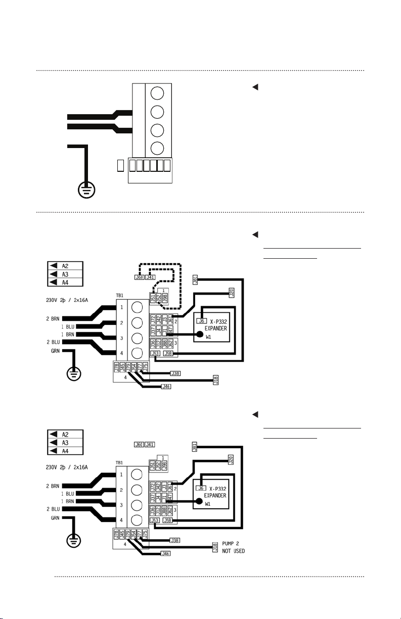
DUAL SERVICE FEED
Setup 5 / Programmation 5 /
Konguration 5
400VAC, 50/60Hz*, 3þ, 16A,
(Circuit Breaker rating =
2x16A max. each phase
line)
DUAL SERVICE FEED
Setup 8 / Programmation 8 /
Konguration 8
Pump 1 and Pump 2 are on line 2; Heater and
Pump 3 and Pump 4 are on line 1.
Pump 1 is on line 2; Heater and Blower are on line 1.
TB1
1
2
3
4
4
J45
J110
J79
J54
J77
J75
J78
GREEN
BLUE
BROWN
230V 1þ / 1x32A
ELECTRICAL SERVICE CONFIGURATION OPTION
For DIP Switch Congured System

16
Pump 1 is on line 2; Heater and Pump 2
are on line 1.
230V 3þ / 3x16A
GREEN
BLUE
1 BROWN
2 BROWN
3 BROWN
TB1
1
2
3
4
4
J78
J45
J79
J54
J77
J75
DUAL SERVICE FEED
Setup 9 / Programmation 9 /
Konguration 9
TRIPLE SERVICE FEED
IMPORTANT - Service must
include a neutral wire, with a line
to neutral voltage of 230VAC.
* BP systems automatically detect
50Hz vs 60Hz.
...continued
ELECTRICAL SERVICE CONFIGURATION OPTION
For DIP Switch Congured System
ADDITIONAL PRODUCT RESOURCES
AND DOWNLOADS
For additional product resources, manuals and other helpful information, please visit our
website at www.clearwaterspas.com and select the “Product Resources” link.
17
5. FILLING YOUR SPA THROUGH
THE FILTER CHAMBER
Before you fill your spa, it is advisable to have your water tested for
hardness (calcium and mineral content). Water from wells usually
contain harder water than urban water supplies. Mineral and metal
imbalances in your water can shorten the life of your spa. Please
contact your local dealer for a proper water analysis or to purchase a
testing kit.
We strongly recommend a high quality “Water Test Kit” for checking
pH and sanitizer levels. Test the water daily until your “user load” is
determined.
Make sure there is no dirt or sediment at the bottom of the tub and
that there is nothing inside the filter compartment before filling with
water. Filling the spa through the filter housing will help to
prevent air locks (trapped pockets of air) in pumps on start up.
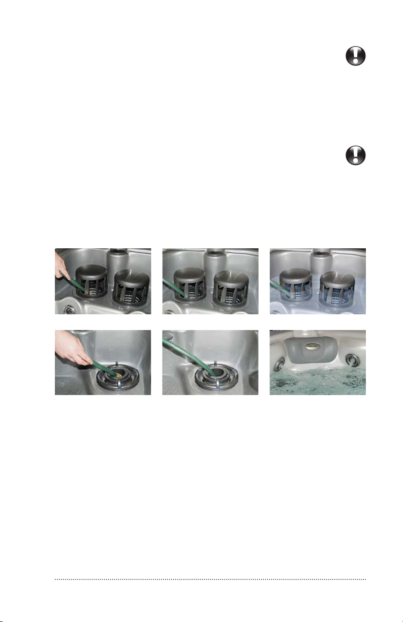
Identify your filter housing and fill as shown:
p TOPACCESS DUALFILTER HOUSING with turbine vane lter cover
p TOPACCESS SINGLEFILTER HOUSING with telescoping weir
1. Place your garden
hose into the filter
housing. This will
ensure that air bubbles
are removed from the
lines while you fill the
spa.
2. Turn the water on so
that most of the water
enters through the lter
chamber.
3. Fill the water to the
proper level – half way
up the lter housing, just
below the head pillow
or just under the neck
jets as shown in pictures
above.
IMPORTANT!
Improperly
balanced
water may
damage your
spa and void
your warranty!
IMPORTANT!
Do not ll your
tub with water
from your hot
water heater!

18
TOPSIDE CONTROLS: TP600
TURNING ON YOUR SPA
PUMP 1
PUMP 2 LIGHT
FLIP HEATLIGHTPUMP 1 PUMP 2
WARM
COOL
PUMP 1
PUMP 2 LIGHT
FLIP HEATLIGHTPUMP 1 PUMP 2
WARM
COOL
Figure 1: TP600 control panel, 6-button (2 pumps)
Spa Models: XS Series Signature Package, U.S./Canada/European
PUMP 1
LIGHT
FLIP HEATLIGHTPUMP 1
WARM
COOL
PUMP 1
LIGHT
FLIP HEATLIGHTPUMP 1
WARM
COOL
Start Up
When the GFCI for the spa is switched on to supply power, a startup
sequence of numbers will appear on the display. If no button is pressed,
LINK will appear after the startup sequence. Press any button to link the
panel with the system. The spa will then enter Priming Mode.The display
will read ‘RUN PUMPS PURG AIR’. Press the Pump Button(s) to turn the
pumps on and off to verify that all the air is purged from the plumbing,
particularly the plumbing associated with the heater. The Light Button
turns the circulation pump on an off during Priming Mode. Priming
Mode will end automatically after 4 minutes. Pressing a Temperature
Button (Cool or Warm) will exit Priming Mode manually. When Priming
Mode ends, thecirculation pump will start. However, the temperature will
not show for a few minutes. Once the water temperature is recognized by the
system, and if it is below the Set Temperature, the heater will start heating
your spa water until the Set Temperature is reached.
Basic Operation
The Up (Warm) and Down (Cool) buttons are often referred to as Temperature
Button(s).Some panels only have a single Temperature Button.
Press a Temperature Button once and the current Set Temperature will
flash on the LCD. The Set Temperature and the actual water
temperature are often different. While the numbers are flashing, press a
Temperature Button again to change the Set Temperature. Press and hold for
faster adjustment. After the new Set Temperature stops flashing, the
actual temperature is displayed again and the new Set Temperature is
programmed. The spa will now heat to the new Set Temperature as
needed. The Light Button turns the Spa Light on and off and is also used in
conjunctions with the Temperature Button(s)to navigate the system
menus.
Figure 2: TP600 control panel, 5-button (1 pump)
Spa Models: XS Series Gold Package, U.S./Canada/European

19
The Light Button turns the Spa Light on and off and is also used in
conjunctions with the Temperature Button(s) to navigate the system menus.
Programming
Refer to the TP600 User Guide for detailed operation,
programming and message instructions.
Navigating the spa operation menu is done using only 2 or 3 buttons on the
control panel. Pressing the Light Button while the Set Temperature is flashing
will enter the menus. Pressing the Light Button after that will proceed through
the menu choices. Pressing a Temperature Button while any menu item is
showing will either edit it directly,or begin an editing sequence.
Depending on the screen displayed, waiting between 10 and 30 seconds will allow
the panel to return to normal operation and a display of spa status.
Filtration
Your spa is factory programmed to circulate and filter water 24 hours a day.
Dual Temperature Ranges
This system incorporates two temperature range settings with independent
temperatures. The High Range is indicated in the display and might be set be-
tween 80°F and 104°F. The Low Range is indicated in the display and might
be set between 50°F and 99°F. Using the Low Range may be more
economical during periods of non-use.
Ready and Rest Modes
READY Mode will allow your spa to heat as needed and to maintain the set
temperature.
Your Clearwater Spa has a dedicated circulation pump that acts as your spa’s
heater pump. In Ready Mode, your spa water will automatically attempt to
maintain its’ set temperature. However, using the spa with the cover open during
extreme cold temperatures, the set temperature may be unattainable.
REST Mode will only allow heating during programmed filter cycles. Since polling
does not occur, the temperature display may not show a current temperature until
the filtration pump has been running for a minute or two. READY/REST Mode
may appear when Pump 1 is active.
Complete Reference
Download the complete User Interface and Programming Guide at
http://service.balboa-instruments.com/zz40940_download.zip
You may also download a programming guide at
http://www.clearwaterspas.com/product-resources/

20
TOPSIDE CONTROLS: TP950, TP800
TURNING ON YOUR SPA
THE MAIN SCREEN
Figure 1: TP950 control panel
Spa Model: Resort Series Signature Package, U.S./Canada/European
Figure 2: TP800 control panel (2 pumps)
Spa Models: Beachcraft Series Signature Package, U.S./Canada
Figure 3: TP800 control panel (3 pumps)
Spa Models: Beachcraft Series Signature Package, European
This manual suits for next models
2
Table of contents
Popular Hot Tub manuals by other brands

Jacuzzi
Jacuzzi Riva 5 Specification sheet

KIRAMI
KIRAMI Premium Grandy Instructions for use

Aquatic
Aquatic Infinity 6 Specification sheet

Dimension One Spas
Dimension One Spas Lotus Bay Specifications

Sundance Spas
Sundance Spas Architectural Series owner's manual

Marquis Spas
Marquis Spas Quest Operating and troubleshooting guide


