manuals.online logo
Brands
  1. Home
  2. •
  3. Brands
  4. •
  5. Cleaveland Controls
  6. •
  7. Switch
  8. •
  9. Cleaveland Controls RFS-4150 User manual

Cleaveland Controls RFS-4150 User manual

·Cleveland Controls
Di-".ision~of
UniControl Inc.
Model·
RFS-4150
/
AIR PRESSURE SENSING SWITCH WITH ADJUSTABLESET POINT
APPLICATION
•'
Model RFS-4150 is a general purpose prov-
ing switch designed for HVAC and Energy
Management-applicatipns. This switch can
be used to sense positive, negative,
or
dif-
ferential air pressure.
GENERAL DESCRIPTION &
OPERATION
The
plated
hotJsiog_contains_a__dlapbLagm~<L~
__
-------,
calibration spring, and a snap-acting switch.
The sample line connections located on
each side
of
the diaphragm accept
o/is",
W',
and
7'\s"
flexible tubing. Various electrical
connections are available.
MOUNTING {FIG. 1)
Select a mounting location which is free
from vibration. The Model RFS-4150 must
be mounted with the diaphragm
in
any verti-
cal plane
in
order to maintain the specified
operating set point. Avoid mounting with the
sample line connections
in
the "up" position.
The standard model
is
surface~mounted
via
th~
two round holes (0.14" dia.) ortwo
of
the
fourslots
(o/is"
wide) on the zinc-plated strap
bracket.The mounting holes and slots are
3-Va"
apart. Custom mounting configurations
are available.
Figure
1:
Mount with the diaphragm
in
any
vertical plane.
-
-~,-~
·~
\1)
AIR SAMPLING CONNECTION
{FIG. 2)
Tri-barbed sample line connectors suitable
to
accept flexible tubing are situated on either
side
of
the diaphragm as shown
in
Figure
2.
The tri-barbed connectors accept
·o/is",
Y..",
and
o/;s"
ID
flexible tubing. For sample
lines up to 10 feet
in
length,
11s"
ID
tubing
is
acceptable. For lines up to 20 feet, use
Y.."
ID tubing.
Locate the sampling probe a minimum
of
Figure 2
INLET
Positive Only
LowerNegative
HigherPositive
NLETL
Negative Only
HigherNegative
LowerPositive
--
-1;5-ductl:liameters-downstreamiromth.::.-.:H.·--+t=lctu.r:e
~---
---
------+
source. Install the sampling probe as close
to the center
of
the airstream as possible.
Refer to Figure 2 to identify the high pres-
sure inlet (H)
and
the low pressure inlet
(L).
Selectone ofthe five application options
listed below, and connect the sample lines
as recommended.
HIGH
PRESSURE
LOW
PRESSURE
0
N.C.
N.O.
Positive
Pressure
Only:
Connect
the
sample line to inlet
H;
inlet L remains open
to the atmosphere. ·
Negative
Pressure
Only:
Connect
the
sample line to inlet
L;
inlefH
remains open
to the atmosphere. · ·
Two Negative Samples: Connectthe higher
negative sample
to
inletL. Connectthe lower
negative sample to inlet'
H. \
Two Positive Samples: Connectthe higher
' positive sampleto inlet
~
Connectthe lower
positive sample to inlet
L.
\
One·Positive and One Negative Sample:
Connectthe positive sampleto inlet
H.
Con-
nect,the negative sample to inlet
L,.
Figure 4
To
prove
excessive
air
flow
or
pressure:
...,.NO
ALARM
c
e-_____-
~--------~~N~~c+-C-0-N-TROL
To
prove
insufficient
air
flow
or
pressure:
JlO
CONTROL
c
0--___:__""
.......
Q--1----
~--------~N~C
ALARM
4.098(104)
ELECTRICAL CONNECTIONS
(FIGURES 3 &
4}
Beforepressure is applied to the diaphragm,
the switch contacts will be in the normally
closed (NC) position. Wire control and alarm
functions
as
shown
in
Figure 4.
FIELD ADJUSTMENT
The adjustment range
of
an RFS-4150 Air-
Switch is 0.15±0.02" we to 5.0"wc.
To
adjust the set point,
t~rn
the adjusting
screw
counterclockwise .until motion
has
stopped. Next, turn the adjusting screw 5
complete turns clockwis'll·to
engage
the
spring.
;•
From this
p~t,
the nexteight turns will be
used fortheiactual calibratibn. Each full turn
represents
a~proximate'iy
0.61" we.
Please note:
To
properly calibrate an air
switch, a digital manometer
or
other mea-
suring device should be used to confirm the
actual set point. ' ·
1-----
.3.066(78)----1
Reference Dimensions in Inches (Millimeters)

Popular Switch manuals by other brands

3Com 16 Plus user guide

3Com

3Com 16 Plus user guide

Shinybow USA SB-5645LCM-CT instruction manual

Shinybow USA

Shinybow USA SB-5645LCM-CT instruction manual

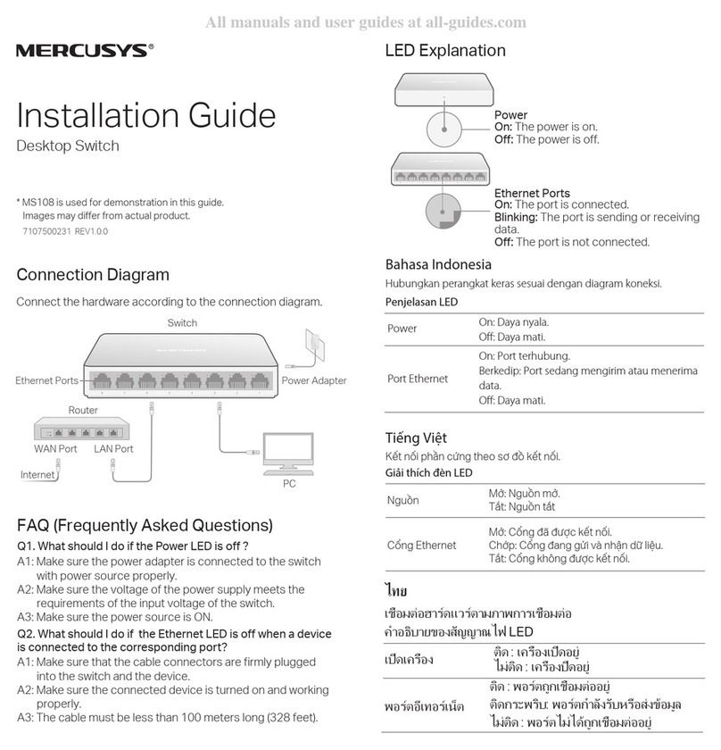
Mercusys MS108 installation guide

Mercusys

Mercusys MS108 installation guide

GEM 125 Series operating instructions

GEM

GEM 125 Series operating instructions

LDG DTS-6 manual

LDG

LDG DTS-6 manual

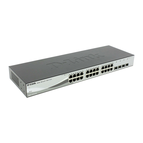
D-Link Web Smart Switch DGS-1210-16 reference guide

D-Link

D-Link Web Smart Switch DGS-1210-16 reference guide

Vixel 9000 series Installation and configuration guide

Vixel

Vixel 9000 series Installation and configuration guide

Spirax Sarco LCS3050 Installation and maintenance instructions

Spirax Sarco

Spirax Sarco LCS3050 Installation and maintenance instructions

Southern States EV-2 Installation instructions manual

Southern States

Southern States EV-2 Installation instructions manual

Digisol DG-CS4616F installation guide

Digisol

Digisol DG-CS4616F installation guide

Campbell SDS-122 instruction manual

Campbell

Campbell SDS-122 instruction manual

Cisco ONS 15530 Hardware installation guide

Cisco

Cisco ONS 15530 Hardware installation guide

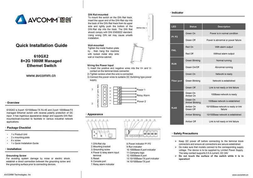
AVCOMM 610GX2 Quick installation guide

AVCOMM

AVCOMM 610GX2 Quick installation guide

Techlogix TL-SM3X1-HDV user manual

Techlogix

Techlogix TL-SM3X1-HDV user manual

AETEK H51-044-30-150 Quick installation guide

AETEK

AETEK H51-044-30-150 Quick installation guide

Exsys EX-1126 manual

Exsys

Exsys EX-1126 manual

Huawei Enterprise S2700 Series Product documentation

Huawei

Huawei Enterprise S2700 Series Product documentation

Niveo N10GSM8F8 Operation manual

Niveo

Niveo N10GSM8F8 Operation manual

manuals.online logo
manuals.online logoBrands
  • About & Mission
  • Contact us
  • Privacy Policy
  • Terms and Conditions

Copyright 2025 Manuals.Online. All Rights Reserved.