Cleco W2119 series Installation and operating instructions
1
Operation & Service Manual
823036 2/01
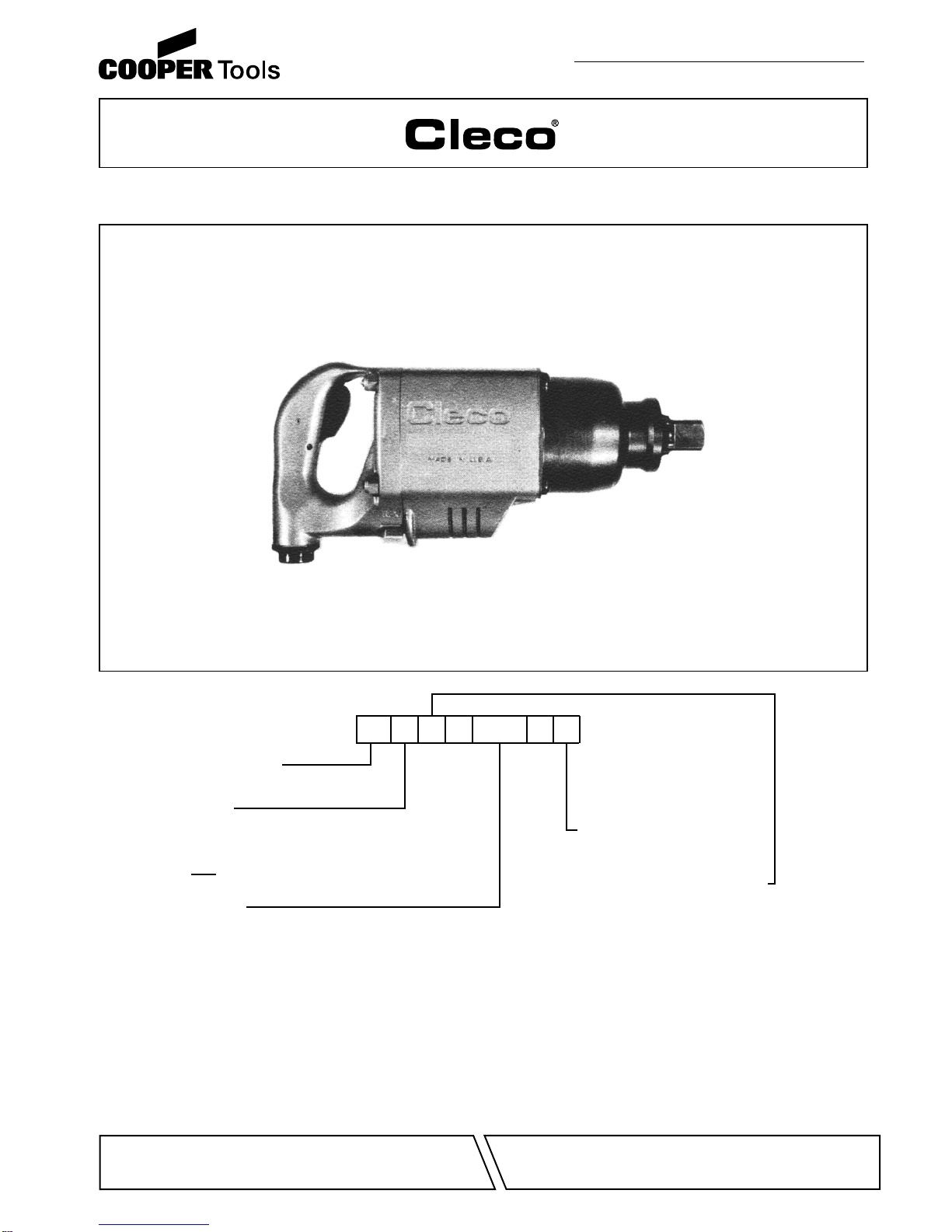
W2119 & W2120 SERIES IMPACTS
Tool Size:
2120
2119
Outside Trigger
W
Inside Trigger
Impact Wrench:
T
Handle:
-- XXXXXXX
Spline Drive (No. 5 Spline)
S
12 1 1/2"
Output Drive:
NORTH AMERICA EUROPE
CooperTools
P.O. Box 1410
Lexington, SC 29071
Cooper PowerTools GmbH & Co.
Postfach 30
D-73461 Westhausen

2
CAUTION!
Personal hearing protection is
recommended when operating
or working near this tool.
SafetyRecommendations
Neverusetheairhoseforsupporting,lifting,orloweringthetool.
Use a safety line or cable on the tool when working in elevated
areas.
Toolswith exposedthrottles shouldnot beusedwhere obstruc-
tionscan holdthethrottle inthe"on" position.Animpactwrench
operating in reverse will move backwards as a nut is removed
andcan trapan operator'shand, makingitdifficulttorelease an
outside trigger. Inside trigger or pistol grip tools are advised for
close quarter operation.
Onlyusesocketsdesignedforusewithimpactwrenches.Never
use a hand tool socket on an impact wrench. Hand tool sockets
can break, resulting in a hazard from flying pieces. Inspect
sockets,retainers,anddrivesregularlyforwearordamage,and
replaceasnecessary.Worn socketsreducepower,causedrive
wear, and increase the chance for breakage and should not be
used.
Impactwrenchesequippedwiththesplinedrivehaveanintegral
socketretainerpinwhichmaybedepressedbyascrewdriveror
similar tool when installing or removing a socket. Tools with
squaredrives 3/4" andlargeruse an aor- ringandpin for socket
retention.Retainers—either pin or integral—should beproperly
engaged to prevent dropping sockets into lower working levels.
Always use socket retainer components recommended by the
socket manufacturer. Never substitute wire, nails, or welding
rods for retaining pins because they are dangerous if thrown
from the tool at free speed, or if the protruding nail or wire is
accidently grasped by the operator.
Some individuals may be susceptible to disorders of the hands
and arms when performing tasks consisting of highly repetitive
motions and/or exposure to extended vibration. Cumulative
trauma disorders such as carpal tunnel syndrome and tendoni-
tis may be caused or aggravated by repetitious, forceful exer-
tions of the hands and arms. Vibration may contribute to a
condition called Raynaud's Syndrome. These disorders de-
velop gradually over periods of weeks, months, and years. It is
For your safety and the safety of others, read and understand
thesafetyrecommendationsbeforeoperatinganimpactwrench.
Always wear protective equipment and clothing.
For additional information on eye protection, refer to Federal
OSHA Regulations, 29 CFR, Section 1910.133, Eye and Face
Protection,andANSIZ87.1,OccupationalandEducationalEye
andFaceProtection. This standard is available from the Ameri-
can National Standards Institute, Inc., 11 West 42nd Street,
New York, NY 10036.
Hearing protection is recommended in high noise areas (above
85dBA). Close proximity ofadditional tools, reflective surfaces,
process noises, and resonant structures can substantially con-
tribute to the sound level experienced by the operator. Proper
hearing conservation measures, including annual audiograms
and training in the use and fit of hearing protection devices may
be necessary. For additional information on hearing protection,
refer to Federal OSHA Regulations, 29 CFR, Section 1910.95,
Occupational Noise Exposure, and American National Stan-
dards Institute, ANSI S12.6, Hearing Protectors.
• Gloves and other protective clothing should be worn as
required, unless they create a greater hazard.
• Do not wear loose fitting clothing, or clothing that may
restrict movement, become entangled or in any way
interfere with the safe operation of the impact.
Clecoimpact wrenches are designed to operate on90psig (6.2
bar) maximum air pressure. If the tool is properly sized and
applied, higher air pressure is unnecessary. Excessive air
pressure increases the loads and stresses on the tool parts,
sockets, and fasteners and may result in breakage. Installation
of a filter-regulator-lubricator in the air supply line ahead of the
tool is highly recommended.
Before the tool is connected to the air supply, check the throttle
for proper operation (i.e., throttle moves freely and returns to
closed position). Being careful not endanger adjacent person-
nel, clear air hose of accumulated dust and moisture. Before
removing a tool from service or changing sockets, make sure
theairlineisshutoff anddrained ofair. Thiswill preventthe tool
from operating if the throttle is accidently engaged.
WARNING!
Impact resistant eye protection
must be worn while operating
or working near this tool.
Outside Trigger Pistol Grip
Rev. Rev.
OKDO NOT USE!
Repetitive work motions and/or vibration
may cause injury to hands and arms.
Use minimum hand grip force consistent
with proper control and safe operation.
Keep body and hands warm and dry.
Avoid anything that inhibits blood circulation.
Avoid continuous vibration exposure.
Keep wrists straight.
WARNING
!
Avoid repeated bending of wrists and hands.
3
SafetyRecommendations
BAD POSTURE
GOOD POSTURE
OVER
CAUTION!
Personal hearing protection is
recommended when operating
or working near this tool.
WARNING!
Impact resistant eye protection
must be worn while operating
or working near this tool.
Read Operating Instructions carefully. Follow
the Safety Recommendations for your safety
and the safety of others.
Hearing protection is recommended in high noise
areas (above 85 dBA). Close proximity of other
tools, reflective surfaces, process noises, and
resonant structures can substantially contribute
to the sound level experienced by the user.
WARNING
!
Repetitive work motions and/or vibration
can cause injury to hands and arms.
Use minimum hand grip force consistent with
proper control and safe operation.
Keep body and hands warm and dry.
Avoid anything that inhibits blood circulation.
Avoid continuous vibration exposure.
Keep wrists straight.
Avoid repeated bending of wrists and hands.
Do not remove this tag until
the operator of this tool has
read these safety precautions.
presently unknown to what extent exposure to vibrations or
repetitive motions may contribute to the disorders. Hereditary
factors, vasculatory or circulatory problems,exposure to cold
anddampness,diet,smokingandworkpracticesarethoughtto
contribute to the conditions.
Tool operators should be aware of the following warning signs
and symptoms so that a problem can be addressed before it
becomes a debilitating injury. Any user suffering prolonged
symptoms of tingling, numbness, blanching of fingers, clumsi-
nessor weakened grip, nocturnal pain in thehand,or any other
disorder of the shoulders, arms, wrists, or fingers is advised to
consultaphysician.Ifitisdeterminedthatthesymptomsarejob
related or aggravated by movements and postures dictated by
the job design, it may be necessary for the employer to take
steps to prevent further occurrences. These steps might in-
clude, but are not limited to, repositioning the workpiece or
redesigningthe workstation, reassigning workers to other jobs,
rotating jobs, changing work pace, and/or changing the type of
tool used so as to minimize stress on the operator. Some tasks
may require more than one type of tool to obtain the optimum
operator/tool/task relationship.
• Tasks should be performed in such a manner that the
wrists are maintained in a neutral position, which is not
flexed, hyperextended, or turned side to side.
• Stressful postures should be avoided. Select a tool
appropriate for the job and work location.
The following suggestions will help reduce or moderate the
effects of repetitive work motions and/or extended vibration
exposure.
•Use a minimum hand grip force consistent with proper
control and safe operation
•Keep body and hands warm and dry
•Avoid anything that inhibits blood circulation
—Smoking Tobacco
—Cold Temperatures
—Certain Drugs
•Keep wrists as straight as possible
•Avoid highly repetitive movements of hands and wrists,
and continuous vibration exposure
Work gloves with vibration reducing liners and wrist supports
are available from some manufacturers of industrial work
gloves.Thesegloves aredesignedtoreduceand moderatethe
effects of extended vibration exposure and repetitive wrist
trauma. Since they vary widely in design, material, vibration
reduction, and wrist support qualities, it is recommended that
the glove manufacturer be consulted for gloves designed for
your specific application. WARNING! Proper fit of gloves is
important. Improperly fitted gloves may restrict blood flow
to the fingers and can substantially reduce grip strength.
Also note that various tool wraps are available from a number
of different manufacturers. Like gloves, these wraps are also
intended to reduce and moderate the effects of extended
vibration exposure. They vary widely in design, material, thick-
ness, vibration reduction, effectiveness, and durability, so con-
sideration must be given to choosing the proper wrap for the
specific application.
This information is a compilation of general safety practices
obtained from various sources available at the date of produc-
tion. However, our company does not represent that every
acceptablesafetypractice isofferedherein, orthatabnormalor
unusual circumstances may not warrant or require additional
procedures. Your work may require additional specific safety
procedures. Follow these procedures as required by your
company.
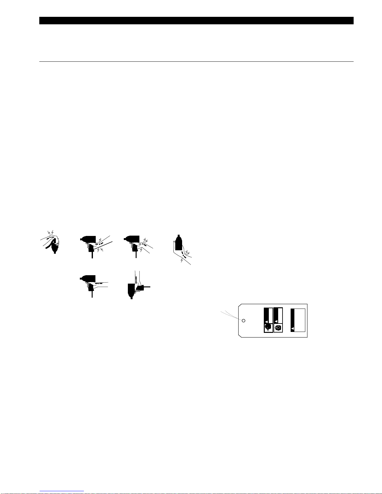
Warnings
The warnings found on these tools are an essential part of the
product. Warnings should be checked periodically for ligibility.
Replacewarningswhenmissingorwhentheinformationcanno
longer be read. Replacements can be ordered as any spare
part.
869976
Formoreinformation,seethelatesteditionofANSIB186.1,
Safety Code for Portable Air Tools, available from the
American National Standards Institute, Inc., 11 West 42nd
Street, New York, NY 10036.
These operating instructions and service manual should
accompany tool if it is subsequently sold or ownership is
changed.

4
GENERAL INFORMATION
AIR SUPPLY
Thetoolisdesignedtooperateon90psig(6.2bar)airpressure
(measuredat the toolair inlet withthe tool running) using a
1/2"(12.7mm) hose up to 8' (2.4m)in length. An automatic
in-linefilter-lubricatoris highlyrecommendedto supplythe
tool with cleanlubricated air. This will keepthe tool in sus-
tained operation and increase its service life.
The air hose should be cleared of accumulated dirt and
moisture,thenone (1)teaspoon(5ml) of1 OWmachineoil
should be poured into the tool's air inlet before connection
the hose to the tool.
IMPORTANT: If a puick-disconnect coupling is used with
thetool,itshouldbeseparatedfromthetoolbyawhiphose.
All tools and hoses should be installed by trained, compe-
tent personnel. Hoses and fittings should be inspected
regularlyforwornordamagedareasandreplacedifneces-
sary.
LUBRICATION
An automatic in-line filter-lubricator is recommended as it
increases tool fif e and keeps the tool in sustained opera-
tion.Thein-linelubricator shouldberegularlychecked and
filled with a good grade of 1 OW machine oil. Proper
adjustment of the in-line lubricator is performed by placing
a sheet of paper next to the exhaust ports and holding the
throttle open approximately 30 seconds. The lubricator is
properly set when a light stain of oil collects on the paper.
Excessiveamountsofoilshouldbeavoided.Intheeventan
in-line lubricator is not used, the oil reservoir in the handle
should be utilized.
The oil reservoir marked "30W oil" should not require
attention until thetool istorn down for inspection purposes;
however, if the tool is on the application for an unduly long
periodoftime,theplugshouldberemovedandthereservoir
checked for the presence of oil. If oil is required, approxi-
mately1-1/4fluidounces(40ml)of30Woilshouldbeadded
to the oil reservoir.
STORAGE
In the event that it becomes necessary to store the tool for
an extended period of time (overnight, weekend, etc.), it
shouldreceiveagenerousamountoflubricationatthattime
and again when returned to service. The tool should be
stored in a clean and dry environment.
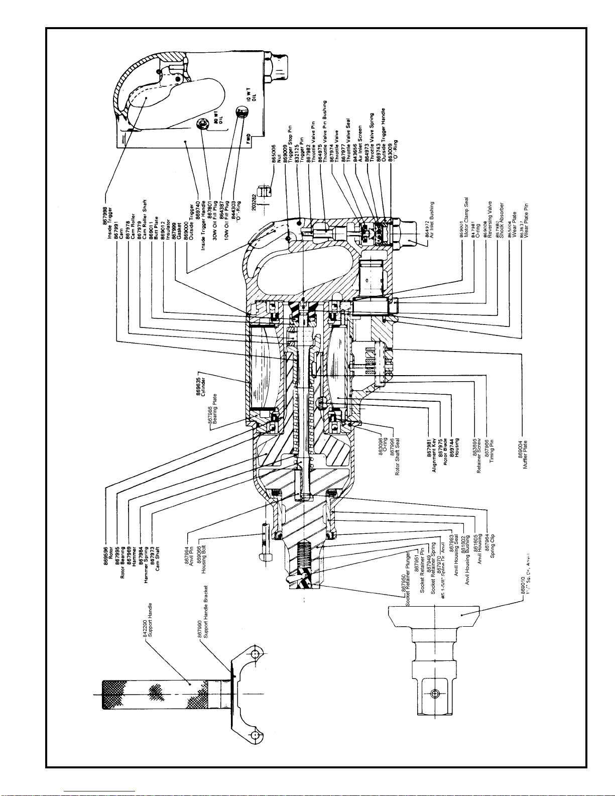
MAINTINANCE - DISASSEMBLY
GENERAL - ALL MODELS
Disconnect the tool from the air supply and unscrew and
remove the four (4) nuts, No. 865006; then remove the
handleassembly,reversingvalve,No.869008,gasket,and
the motor clamp seal, No. 869001, from the rear of the
motor unit.
Drivethefour(4)housingbolts,No.869066,outthefrontof
themotorunit.Removingtheanvilhousing,No.861605,will
allow the complete impacting mechanism to slip out the
front of the motor unit. The anvil housing may need to be
rotated to clear the anvil and hammer lugs.
The impact wrench is now separated into four (4) basic
assemblies. See the following paragraphs for commplete
disassembly instructions on these assemblies
ANVIL HOUSING
For better performance, it is recommended that the anvil
housingseal, No. 867993, be replaced duringeach repair.
Thesealmayberemovedbypryingitoutwithascrewdriver.
Shouldtheanvilhousingbushing,No.861602,needreplac-
ing, the housing seal will have to be removed as outlined
abovePressthehousingbushingouttherearofthehousing
using a bushing driver 2-3/16" in diameter.
IMPACT MECHANISM
Clampthehammer,No867969,horizontallyinasoftjawed
viseanddrivetheanvil*awayfromthehammerusingasoft
hammerThiswillallowtheanvilpin,No867994,springclip,
No867964.andhammerspringNo.867984toberemoved
from the front of the cam shaft, No 867973
Remove the hammer from the vise and slip the cam shaft
and related components out of the rear of the cam, No.
867991. Remove the shock absorber, No. 867980, (slight
press fit) from the rear of the cam shaft. This will allow the
insulator, No. 869012, butt plate, No. 869011, cam roller,
No.869278,andcamrollershaft,No867979,toberemoved
from the cam shaft.
Slip the cam, No. 867991, out of the rear of the hammer,
being careful not to lose the timing pin, No. 867966.
*NOTE:Onthesplinedriveanvils,shouldanyofthesocket
retainerpartsneedreplacing,a5/32"holeshouldbedrilled
in the socket retainer plunger, No. 867950, as shown in
Figure3.Insertapinpunchinthedrilledholeandlightlytap
thepunchunderthesocketretainerpin,No.867951.Pryon
the punch to pop the pin out of its pocket in the plunger.
MOTOR UNIT
Set the front of the housing, No. 869744, on a cylinder (4-
112''I.D.x5''long)andusingasuitabledriver(2-1/8"O.D.)
drivetherotoroutoftherearrotorbearing,No.867995.This
willremovethefrontbearingplate,No.867985,six(6)rotor
blades, No. 867975, and rotor from the housing. Invert the
housing on the fixture and use the rotor to drive the rear
bearing plate assembly from the housing. The cylinder

5
should not be removed from the housing unless replace-
mentisnecessary.Ifcylinderreplacementisnecessary,a4-
5/32" O.D. bushing driver (with a suitable relief for the
alignment key, No. 867981) should be used to press the
cylinder out of the housing.
Remove the rotor bearings, No. 867995, from the bearing
plates for inspection. For better performance, it is recom-
mendedthat the rotor shaftseals, No. 867996, bereplaced
during each repair.
NOTE: UNLESS THE "0" RINGS, NO. 844309, LOCATED
ONTHEO.D. OF THEBEARINGPLATE ARESEVERELY
DAMAGED, THEY SHOULD NOT BE REMOVED. IF RE-
PLACEMENTISNECESSARY,REPLACEMENT"0"RINGS
SHOULDBEINSTALLEDWITHAFASTCURECONTACT
ADHESIVE ("LOCTITE" 404).
For cleaning and inspection of the three (3) muffler plates,
No. 869004, unscrew the retainer screw, No. 883695.
HANDLEASSEMBLIES
Both the inside and outside trigger handle assemblies are
disassembled using the same procedure. Unscrewing the
air inlet bushing, No. 864972, will allow the "0"ring, No.
863009, air inlet screen, No. 843656, throttle valve spring,
No. 864973, throttle valve No. 867974, throttle valve seal,
No. 867977, and throttle valve pin, No. 867982, to be
removed from the handle.
If the throttle pin bushing, No. 864975, should need replac-
ing, tap. the I.D. of the bushing with a 114"-20 thread tap.
Inserta114-20 boltof the appropriatelength andclampthe
boltin the vise. Drivethe handle away fromthe vise using a
soft mallet.
Ifthetriggershouldneedreplacing,onlythetriggerpin(solid
pin), No. 832125, need be removed.
MAINTENANCE - REASSEMBLY
CLEANING AND INSPECTION
All parts should be cleaned in a solvent and inspected for
wearor damage.If rotor bladesmeasure lessthan 7116 on
either end, they should be replaced. Rotor bearings should
bereplaced if they feel rough after cleaning or show exces-
sive looseness.
HANDLE ASSEMBLY
Wheninstailingthetriggeruseapinslightlysmallerthanthe
hole in the handle to locate the trigger when driving the
trigger pin, No 832125. into the handle.
If the throttle valve bushing No 864975, was removed, the
newbushingshouldbepressedintoadepthof115/16"plus
or minus 1/64 from the bottom face of the handle.
Inspect the throttle valve seal, No, 867977, for wear or
deterioration. If replacement is necessary, the new seal
should be pushed (cupped face first) on the throttle valve,
No.867974,fromthetaperedend.Inspectthe"O"-ring,No.
863009,andreplace if necessary.Cleanthe threadsonthe
airinletbushing,No864972,andapply"LOCKTITE"No.271
to the threads.
Now install the throttle valve pin, No 867982, and throttle
valve assembly into the handle. Place the inlet air screen,
No.843656,aridthrottlevalvespring,No.864973,intheair
inlet bushing and screw the bushing into the handle. The
bushing should be torqued to 80 It lbs. minimum.
MOTOR UNIT
Insertthethree(3)mufflerplates.No.869004,andinstallthe
retaining screw, No. 883695.
During reassembly of the bearing plates, No. 867985, the
rotor shaft seals, No. 867996, should be installed with their
"lips'' facing out (visible after installation). When installing
therotorbearings,No.867995,pressonthebearing'souter
race. Lubricate both the seals and rotor bearings with 30W
oilbeforeassemblyintothemotorunit.Inspectthe"O"-ring,
No.863096,and replaceifnecessary. This"O"-ring isused
only on the front bearing plate (both bearing plates are
identical).
Ifthecylinderwasremoved,thenewcylinder(withalignment
key,No.867981,inplace)shouldbepressedinfromtherear
ofthemotorhousingtoadepth5/8"fromtherearfaceofthe
housing.
Lubricatethe"O"-ringsonthe O.D.oftherearbearing plate
assembly and press the assembly into the housing. When
installing either bearing plate assembly, be sure the "O"-
rings line up with the air ports in the housing. Invert the
housing and install the rotor with the end stamped ''REAR"
into the rear rotor bearing, No. 867995.
Insertthesix(6)rotorblades,No.867975,thenlubricatethe
"O''-ringsonthefront bearing plateassemblyandpress the
assembly into the housing. NOTE: Be sure '0--ring, No.
863096, is in place on the front bearing plate.
IMPACT MECHANISM
All parts should receive a thin coating of 30W oil before
assembly.
Insertthetimingpin,No.867966,intotherecesslocatedon
the small O.D. of the cam, No. 867991, and then install the
cam and pin into the rear of the hammer, No. 867969.
Installthecamrollershaft,No.867979,inthecamshaft,No.
867973. Put the cam roller, No. 867978, on the roller shaft
and slip the butt plate, No. 869011, insulator, No. 869012,
and shock absorber, No. 867980, onto the rear of the cam
shaft. Hold the cam shaft vertically on the work bench with
the shock absorber down and tap the end of the cam shaft
withasoftmallettoseatthecamshaftintheshockabsorber.
Slipthecamshaftandrelatedcomponentsthroughthecam
and hammer assembly. Install the hammer spring, No.
867984 spring clip, No. 867964, and anvil pin, No. 867994,
6
onto the front of the cam shaft and hammer assembly.
Rotatethe springclip toaccept theanvil pinand theninstall
theanvilontop oftheassembly (be suretheslot intheanvil
lines up with the anvil pin) and drive the anvil down until the
spring clip engages the recess in the anvil.
To install the socket retainer pin, No 867951, in the spline
drive anvil, insert socket retainer spring, No. 867949, and
socket retainer plunger, No. 867950 into the anvil and then
drive the socket retainer pin radially into the plunger.
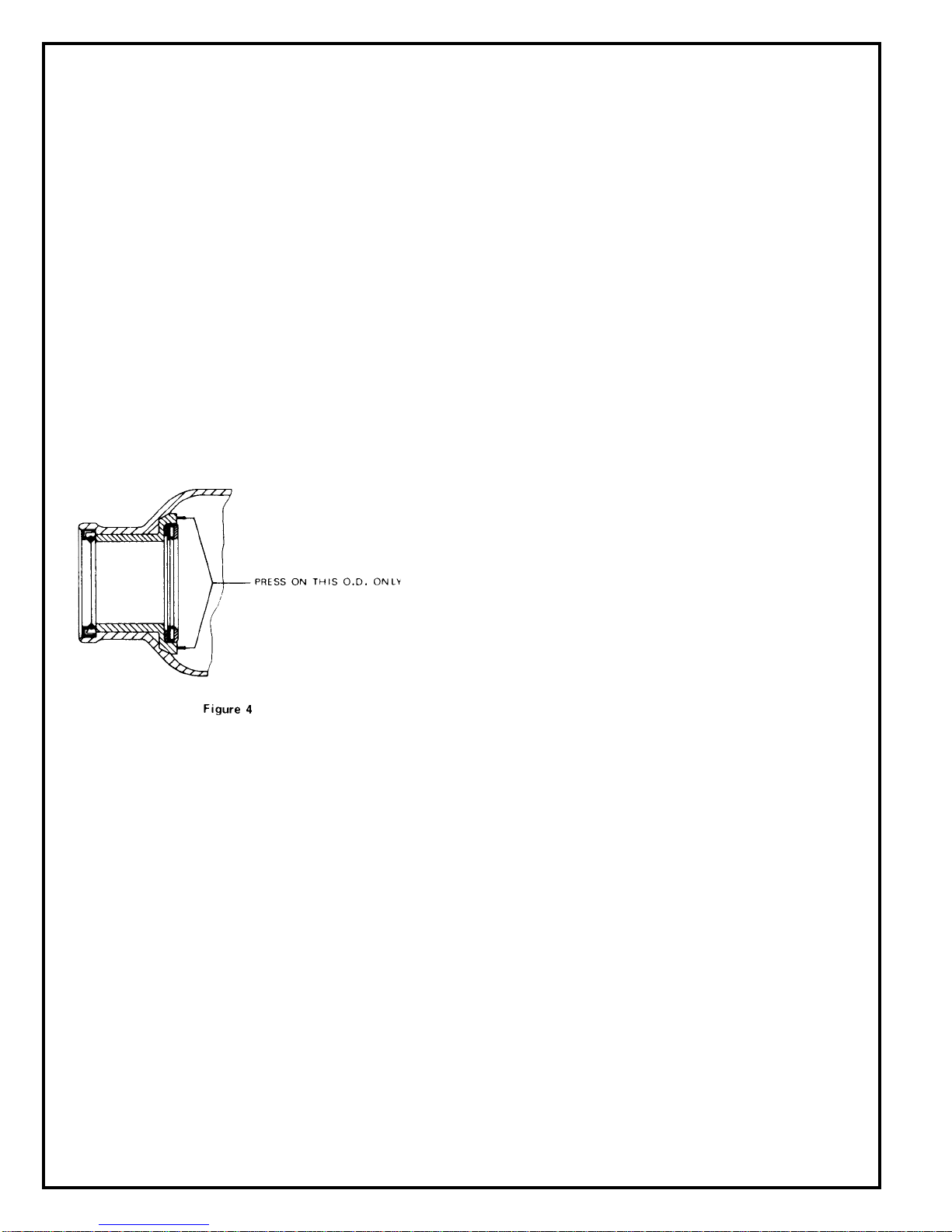
ANVIL HOUSING
If the anvil housing bushing, No 861602, is replaced, it
should be pressed in as shown in Fig. 4.
When replacing the anvil housing sea), No 867993, the
housing bore should be cleaned with a solvent and then
coatedwith''PERMATEX"AviationForm-A-GasketNo.3H,
andthenbeallowedtoairdryatleastfour(4)minutesbefore
pressingintheseal.Pressthesealinwithits"lip"towardthe
boreofthehousing(''Lip''shouldnotbevisibleafterassem-
bly.)
GENERAL- ALL MODELS
Coat the hammer and rotor splines with 30W oil and insert
theimpactmechanismintothefrontoftherotorLubricatethe
anvilhousingsealandbushingwith30Woilandinstallonthe
unitbeingsurethecontouroftheanvilhousingmatchesthat
of the motor housing The anvil and hammer lugs should be
in line with the recess in the make-up lip located in the anvil
housing.Installthedeadhandlebracket,No.867990,onthe
leftside ofthe tooland insertthe four(4) housing bolts. Tap
theboltswithahammeruntiltheanvilhousingseatsagainst
the motor housing.
ClarnpthetoolverticallyinaviseandinstallthegasketInsert
-0--ring,No.847981,intothereversingvalveboreandinstall
thereversingvalve,No.869008.Applyathincoatofgrease
to the motor clamp seal, No 869001, and place it into the
handle recess.
Put the handle on the tool and install the four (4) nuts, No.
865006. Torque these nuts to 20 ft. lbs. minimum.
Laythetoolonitsrightsideandremovethe30Woilfillplug,
No. 867801. Fill the reservoir with a good grade of 30W oil
up to the level of the fill indicator pin located in the reservoir
(approximately 1 - 1-1/4 fluid Ounces).
Place a couple of teaspoons of 10W machine oil in the air
inlet bushing before attaching the air hose to ensure imme-
diate lubrication of all motor parts.
SAFETY CHECK
Alltoolsshouldbetestedafterrepairorreplacementofparts
to assure that they are functioning properly.
7

8
PART NO.
842290
861602
861605
867949
867950
867951
867964
867966
867969
867970
867973
867976
867978
867979
867980
867983
PART NO.
867984
867987
867988
867990
867991
867993
867994
869010
869011
869012
869066
NAME OF PART
Support Handle
Anvil Housing Bushing (incl. 867976, 867983, 867987,
867988)
Anvil Housing (incl. 861602, 867993)
Socket Retainer Spring
Socket Retainer Plunger
Socket Retainer Pin
Spring Clip
Timing Pin
Hammer
#5 1-5/8" Spline Drive Anvil
Cam Shaft
Thrust Race
Cam Roller
Cam Roller Shaft
Shock Absorber
Cushion
NAME OF PART
Hammer Spring
Thrust Bearing
Thrust Race
Support Handle Bracket
Cam
Anvil Housing Seal
Anvil Pin
1-1/2" Sq. Dr. Anvil
Butt Plate
Insulator
Housing Bolt
QTY.
1
1
1
1
1
1
1
1
1
1
1
1
1
1
1
1
QTY.
1
1
1
1
1
1
1
1
1
1
4
PARTS LIST — IMPACT MECHANISM

9
PART NO.
863096
863637
865004
867971
867975
867981
867985
867995
PART NO.
867996
869001
869004
869596
869635
869744
883695
NAME OF PART NAME OF PART
Rotor Shaft Seal
Motor Clamp Seal
Muffler Plate
Rotor
Cylinder (W-2119)
Housing (incl. 863637, 865004, 869004,883695)
Retainer Screw
QTY.
1
1
1
1
6
1
2
2
QTY.
1
1
1
1
1
PARTS LIST — MOTOR UNIT
O-ring 3-1/4" X 3-1/2"
Wear Plate Pin
Wear Plate
Cylinder (W-2120)
Rotor Blade
Alignment Key
Bearing Plate (incl. 844309)
Rotor Bearing

10
PART NO.
203282
832125
843656
844303
847981*
863009
864387
864972
864973
864975
865006*
PART NO.
867801
867974
867977
867982
567998
867999*
869000
869008*
869009
869740
869743
NAME OF PART
Washer
Trigger Pin
Air Inlet Screen
O-ring 3/16" X 5/16"
O-ring 1-3/8" X 1-1/2"
O-ring 3/4" X 7/8"
10W Oil Fill Plug
Air Inlet Bushing
Throttle Valve Spring
Throttle Valve Pin Bushing
Nut
NAME OF PART
30W Oil Fill Plug
throttle Valve
Throttle Valve Seal
Throttle Valve Pin
Inside Trigger
Gasket
Outside Trigger
Reversing Valve
Trigger Stop Pin
Inside Trigger Handle (incl. 864975)
Outside Trigger Handle (incl. 864975)
QTY.
2
1
1
1
1
1
1
1
1
1
4
QTY.
1
1
1
1
1
1
1
1
1
1
1
PARTS LIST — HANDLES
*Denotes parts not included in subassemblies listed below.
The complete handle can be ordered as a subassembly using the part numbers listed below.
Outside Trigger - 861867 Inside Trigger - 861863

11
NOTES

12
CooperTools
670 Industrial Drive
Lexington, SC 29072
Phone: (803) 359-1200
Fax: (803) 359-2013
www.cooperindustries.com
This manual suits for next models
1
Table of contents
Other Cleco Nail Gun manuals


Popular Nail Gun manuals by other brands


Makita
Makita DPT353 instruction manual

BEA
BEA R 130 - 957E Operator's manual

Hitachi
Hitachi NR 90AA Handling instructions

Bostitch
Bostitch N89C Operating and maintenance manual

Milwaukee
Milwaukee 7150-21 Operator's manual

Hitachi
Hitachi NR90AD - Clipped Head to 3-1 Framing Nailer Instruction and safety manual


