Cleco 19RAA02AM2 User manual

For additional product information visit our website at http://www.apextoolgroup.com
Service Manual
PL12-1014EN
10/16/2014
19RA Series
Right Angle Nutrunner

Page 2
PL12-1014EN
10/16/2014
Cleco®
General Information
For this Instruction Manual
This Instruction Manual is the Original Instruction Manual intended for all persons who will operate and maintain
these tools.
This Instruction Manual
• provides important notes for the safe and efcient use of these tools.
• describes the function and operation of the 19RA series tools.
• serves as a reference guide for technical data, service intervals and spare parts ordering.
• provides information on optional equipment.
Identication text:
19RA represents all models of the right angle pneumatic nutrunner as described in this manual
Ú indicates a required action
• indicates a list
<..> indicates a reference number from the exploded parts drawings
Arial indicates an important feature or instruction written in Arial Bold
Identication graphic:
¢indicates a directional movement
òindicates a function or force
Copyright protection:
Apex Tool Group, LLC reserves the right to modify, supplement or improve this document or the product without
prior notice. This document may not be reproduced in any way, shape or form, in full or parts thereof, or copied
to another natural or machine readable language or to a data carrier, whether electronic, mechanical, optical or
otherwise without the express permission of Apex Tool Group, LLC.

Page 3
PL12-1014EN
10/16/2014
Cleco®
Nomenclature
19 R A X XX XX X
Tool Series
19
Tool Style
R = Reversible Nutrunner
Tool Configuration
A =
Right Angle - Lever
Torque Control Mechanism
A = Clecomatic Clutch
S = Stall
Maximum Torque
02 = 2.1 Nm 02 = 2.7 Nm
03 = 3.1 Nm 03 = 3.2 Nm
04 = 4.8 Nm 04 = 3.6 Nm
05 = 5.7 Nm 05 = 5.2 Nm
06 = 6.0 Nm 06 = 6.2 Nm
07 = 6.8 Nm
09 = 8.5 Nm
11 = 11 Nm
12 = 11 Nm
Right Angle Head
AM = Medium Duty
AH = Heavy Duty
Output Drive
2 = 1/4" Square Drive (AM & AH) *
3 = 3/8" Square Drive (AH)
516 = 5/16" Internal Hex (AM)
Q = Quick Change Spindle (AH)
* AH2 Head max torque 50 in. lbs.
19RAA
19RAS

Page 4
PL12-1014EN
10/16/2014
Cleco®
Contents
1 Safety 6
1.1 Warning and notes................................................................................................. 6
1.2 Basic requirements for safe working practices ...................................................... 6
1.3 Operator training.................................................................................................... 7
1.4 Personal protective equipment .............................................................................. 7
1.5 Designated use...................................................................................................... 7
1.6 Codes and standards ............................................................................................ 7
1.7 Noise and vibration................................................................................................ 7
2 Scope of supply, transport and storage 8
2.1 Items supplied ....................................................................................................... 8
2.2 Transport ............................................................................................................... 8
2.3 Storage ..................................................................................................................8
3 Product description 8
3.1 General description ............................................................................................... 8
3.2 Operation and functional elements........................................................................ 9
4 Accessories 9
5 Before initial operation 10
5.1 Ambient conditions .............................................................................................. 10
5.2 Air supply............................................................................................................. 10
5.3 Connecting the air supply to the tool ................................................................... 10
5.4 Tool set up ........................................................................................................... 10
5.4.1 Setting the torque ................................................................................................ 10
6 First operation 11
6.1 Puting into use..................................................................................................... 11
7 Troubleshooting 11
8 Maintenance 11
8.1 Service schedule ................................................................................................. 12
8.1.1 Calculating a customer specic maintenance plan.............................................. 12
8.2 Lubricants ............................................................................................................12
9 Repair instructions 13
9.1 Motor disassembly and reassembly .................................................................... 13
9.2 Trip rod sizing ...................................................................................................... 13

Page 5
PL12-1014EN
10/16/2014
Cleco®
Contents
10 Spare parts
10.1 19RAA series nutrunner ...................................................................................... 14
10.2 19RAS series nutrunner ...................................................................................... 16
10.3 Motor assembly ................................................................................................... 18
10.4 301967PT Gearing assembly .............................................................................. 20
10.5 301086 Gearing assembly................................................................................... 20
10.6 301968PT Gearing assembly .............................................................................. 22
10.7 301969PT Gearing assembly .............................................................................. 22
10.8 302016PT Gearing assembly .............................................................................. 24
10.9 301970PT Gearing assembly .............................................................................. 26
10.10 301982PT Clecomatic clutch assembly............................................................... 28
301992PT Clecomatic clutch assembly............................................................... 28
10.11 301978PT Clecomatic clutch assembly............................................................... 30
10.12 936566PT AM2 Attachment (1/4” square drive) .................................................. 32
10.13 936530PT AH2 Attachment (1/4” square drive)................................................... 34
936531PT AH3 Attachment (3/8” square drive)................................................... 34
302030PT AHQ Attachment (Quick Change) ...................................................... 34
10.14 201711 AM516 Attachment (5/16” Internal Hex).................................................. 36
11 Technical data 38
11.1 19RAA Specications .......................................................................................... 38
11.2 19RAS Specications .......................................................................................... 38
12 Service 39
12.1 Replacement parts .............................................................................................. 39
12.2 Tool repairs .......................................................................................................... 39
12.3 Warranty repairs .................................................................................................. 39
13 Disposal 39

Page 6
PL12-1014EN
10/16/2014
Cleco®
General Information
1 Safety
1.1 Warnings and notes
Warning notes are identied by a signal word and a pictogram.
• The signal word indicates the severity and probability of the impending danger.
• The pictogram indicates the type of danger.
---------------------------------------------------------------------------------------------------------------------------------------
WARNING identies a potentially hazardous situation which, if not avoided, may result in serious
injury.
---------------------------------------------------------------------------------------------------------------------------------------
---------------------------------------------------------------------------------------------------------------------------------------
CAUTION identies a potentially hazardous situation which, if not avoided, may result in minor or
moderate injury or property and environmental damage.
---------------------------------------------------------------------------------------------------------------------------------------
---------------------------------------------------------------------------------------------------------------------------------------
NOTE identies general information which may include application tips or useful information but no
hazardous situations.
---------------------------------------------------------------------------------------------------------------------------------------
---------------------------------------------------------------------------------------------------------------------------------------
Important information that must be read and understood by all personnel installing, operating or
maintaining this equipment.
---------------------------------------------------------------------------------------------------------------------------------------
1.2 Basic requirements for safe working practices
All personnel involved with the installation, operation or maintenance of these tools must read and
understand all safety instructions contained in this manual. Failure to comply with these instructions
could result in serious injury or property damage.
These safety instructions are not intended to be all inclusive. Study and comply with all applicable
National, State and Local regulations.
---------------------------------------------------------------------------------------------------------------------------------------
Work Area:
ÚEnsure there is enough space in the work area.
ÚKeep the work area clean.
ÚKeep the work area well ventilated.
Personnel Safety:
ÚInspect the air supply hoses and ttings. Do not use damaged, frayed or deteriorated hoses.
ÚMake sure the air supply hose is securely attached to the tool.
ÚEnsure a secure standing position and maintain balance.
ÚMake sure the throttle is positioned relative to the head so the throttle will not become wedged
against an adjacent object in the ON position due to torque reaction.
ÚIf the tool is to be reversed, locate the throttle in a neutral position to prevent entrapment.

Page 7
PL12-1014EN
10/16/2014
Cleco®
General Information
ÚKeep the tool clean and dry to provide the best possible grip.
ÚFirmly grasp the handle of the 19RA and apply the socket or bit to the application before starting.
ÚBe prepared for high short-term reaction torques.
Safety working with and around fastening tools:
ÚUse only power tool sockets and bits available from Apex Tool Group.
ÚInspect socket or bit for visible damage and cracks. Replace damaged items immediately.
ÚDisconnect the air supply before installing or replacing the socket or bit.
ÚDo not attach the socket or bit at a slant.
ÚMake sure the socket or bit is fully assembled on the drive and locked in postion.
---------------------------------------------------------------------------------------------------------------------------------------
1.3 Operator training
All personnel must be properly trained before operating the 19RA tools. The 19RA tools are to be
repaired by fully trained personnel only.
1.4 Personal protective equipment
When working
• Wear eye protection to protect against ying metal splinters.
• Wear hearing protection
Danger of injury by being caught by moving equipment.
• Wear a hairnet
• Wear close tting clothing
• Do not wear jewelry
1.5 Designated use
The 19RA is designed exclusively for fastening and releasing threaded fasteners.
The 19RAA series nutrunners are equipped with an adjustable Clecomatic clutch. The tool will shut off
the instant the clutch reaches its adjustable preset torque. This action provides an accurate method of
controlling torque without sacricing tool speed.
The 19RAS series are stall type nutrunners. The tool runs down the fastener until the torque resistance
in the fastener causes the tool to stall. When the tool stalls, the throttle is released by the operator and
the tool is removed from the application. Stall type tools can produce accurate torques, especially on
applications with varying torque rates; however, their torque output can be easily inuenced by the
operator and by uctuations in the air line pressure. Operators should be instructed to allow the tool to
stall before releasing the throttle and to avoid pulling or wrencing the tool after it stalls.
• Do not modify the 19RA, any guard or accessory.
• Use only with accessory parts which are approved by the manufacturer.
• Do not use as a hammer, pry-bar or any other improper usage.
1.6 Codes and standards
It is mandatory that all national, state and local codes and standards be followed.
1.7 Noise and vibration
Noise level ≤ 75 dB(A) free speed (without load) according to ISO 12100: 2011
Vibration values < 2.5 m/s2 according to ISO 12100: 2011

Page 8
PL12-1014EN
10/16/2014
Cleco®
General Information
2 Scope of supply, transport and storage
2.1 Items supplied
Check shipment for transit damage and ensure that all items have been supplied:
1 19RA
1 PL12-1014EN instruction manual
1 Declaration of Conformity
1 Lubrication sheet
1 Warranty statement
2.2 Transport
Transport and store the 19RA in the original packaging. The packaging is recyclable.
2.3 Storage
For short term storage (less than 2 hours) and protection against damage:
ÚPlace the 19RA in a location on the workbench to avoid accidental depression of the lever.
or
ÚSuspend the 19RA from a suitable balancer or tool positioner.
For storage longer than 2 hours:
ÚDisconnect the air supply from the 19RA
3 Product description
3.1 General description
• Right angle pneumatic powered nutrunner
• Lever actuated
• Clockwise/counterclockwise rotation
• 19RAA models: adjustable Clecomatic clutch
19RAS models: stall torque shutoff
• Low vibration level
Object Time Period Storage Temperature
19RA without air supply No guideline -13°F to 104°F (-25°C to 40°C)

Page 9
PL12-1014EN
10/16/2014
Cleco®
Scope of Supply, Transport and Storage
3.2 Operation and functional elements
This section describes the operational and functional elements of the 19RA.
4 Accessories
6 1
24
5
3
7
Ref. Description
1 Air Inlet
2 Reversing Ring
3 Throttle Lever
4 Motor and Gearing
5 Clecomatic Clutch (19RAA models)
6Right Angle Nutrunner Attachment
7 Square Drive Output Spindle
Non-Reversible Kit
Part Number: 207030
Torque Signal Kit
19RAA Clecomatic clutch models only
Part Number: 301106
Exhaust Overhose
Part Number: 207019
TVP-100 Series Torque Verier
Part Number:
TVP-110-15-U (115VAC) EN
TVP-110-30-U (230 VAC) EN

Page 10
PL12-1014EN
10/16/2014
Cleco®
General Information
5 Before initial operation
5.1 Ambient conditions
Ambient temperature: 41°F (5°C) to a maximum of 104°F (40°C)
Acceptable relative humidity: 25% to 90%, non-condensing
5.2 Air supply
To attain consistent results, maintain a constant working pressure using a suitable air line unit consisting
of a lter, regulator and lubricator.
ÚThe inside diameter of the air hose must be free of residue, clean if necessary.
ÚSpray a few drops of light air tool oil into the air inlet adapter.
ÚAdjust the lubricator to a minimum setting to reduce the amount of excess oil in the exhaust air.
Oil identification
5.3 Connecting the air supply to the tool
The air hose can disconnect from the tool by itself and whip around uncontrollably.
ÚTurn off the compressed air before connecting to the tool.
ÚSecurely connect the air hose to the tool.
ÚTurn on the compressed air.
5.4 Tool set up
The tool must be congured for the application.
5.4.1 Setting the torque
Danger of injury from accidental start up.
Turn off the compressed air before adjusting the clutch.
ÚUsing the clutch adjustment tool provided, turn clockwise for maximum torque or counter-
clockwise for minimum torque.
Note: For best results, start from minimum torque and adjust in the maximum direction until desired
torque is achieved.
Parameter Description
Air Hose
Minimum inside diameter: 3/16" (4,7 mm)
Maximum length: 16.4' (5 m)
Working pressure range
58 to 101.5 psi (400 to 700 kPa)
Recommended: 90 psi (620 kPa)
Compressed air
Air quality according to ISO 8573-1, quality class 2.4.3
The compressed air must be clean and dry.
Part No. Packaged Designation Vendor
540397 1 Quart (0.94 liter) Airlube 10W/NR-420LB DR Fuchs Lubricants Co.
533485 1 US Gallon (3.78 liter) Airlube 10W/NR-420LB DR Fuchs Lubricants Co.
204963
#1 Phillips
Clutch Adjustment Tool
Page 11
PL12-1014EN
10/16/2014
Cleco®
General Information
6 First operation
6.1 Putting into use
We recommend the use of a reaction bar for higher torque applications to
prevent uncontrollable reaction of the tool when rundown shut off is achieved.
This use is dependent on the following factors: torque, joint, air pressure,
form of tool, and the operator. Consider the use of a reaction bar to prevent
personal injury.
ÚMake sure the air supply is securely attached and the compressor is turned on.
ÚMake sure the reverse ring is in the correct position.
ÚPlace the socket or bit on the application and depress the lever to start the rundown.
ÚWhen the tool shuts off after reaching the set torque, release the lever.
ÚRemove the tool from the application.
7 Troubleshooting
8 Maintenance
Danger of injury from accidental start up.
Turn off the compressed air before performing any maintenance.
Malfunction Possible causes Remedy
No or low air pressure
Make sure there is adequate air pressure at
the tool air inlet
Reversing ring out of position
Make sure the reversing ring is in the
clockwise or counterclockwise position
Trip rod spring out of position Tool disassembly required
Broken gears
Tool disassembly required (parts
replacement)
Torque set to high Reduce the torque setting
Working pressure < 58 psi (400 kPa) Increase the working air pressure
Teeth on adjusting wrench worn or
broken
Replace adjusting wrench
Teeth on adjustment nut worn or
broken
Clutch disassembly required (parts
replacement)
Reduced air pressure Check air supply line for any obstructions
Lack of lubrication
Check the air line lubricator to make sure it is
full of lubricant and is working properly
Motor exhaust air is obstructed Clean or replace bronze mufflers
Swollen rotor blades from excessive
moisture
Check the air line filter, empty reservoir if
necessary
Worn rotor blades
Tool disassembly required (parts
replacement)
Worn gears or bearings
Tool disassembly required (parts
replacement)
Loose inlet adapter Tighten inlet adapter
Worn o-ring on inlet adapter Replace o-ring
Tool does not
start
Tool does not shut
off
Unable to adjust
torque
Tool loses power
Air leak at inlet
adapter
Page 12
PL12-1014EN
10/16/2014
Cleco®
General Information
8.1 Service schedule
Only qualied and trained personnel are permitted to perform maintenance on these tools.
Regular maintenance reduces operating faults, repair costs and downtime. In addition to the following
service schedule, implement a safetu related maintenance program that takes the local regulations for
repair and maintenance for all operating phases of the tool into account.
This maintenance schedule uses values that are valid for most applications. For a specic maintenance
interval, refer to 8.1.1 Calculating a customer-specic maintenance plan.
8.1.1 Calculating a customer specic maintenance plan
A service interval W(1, 2, 3) depends on the following factors:
8.2 Lubricants
For proper function and long service life, use of the correct grease is essential.
Maintenance
Interval
Rundowns
Daily Daily
Visual inspection of air supply hose and connections
Inspect airline filter, regulator and lubricator for proper operation
Check the tool excessive vibration or unusual noises
Visual inspection of all external components of the tool
W1 100,000
Inspect the air hose for damage or wear
inspect the square drive output spindle for damage or wear
Inspect the air inlet adapter for a secure fit
Check the maximum free speed
W2 500,000
Check individual parts and replace if necessary
Replace O-rings and seals
Clean bronze mufflers
W3 1,000,000
Check individual parts and replace if necessary
Throttle valve
Motor
Gearing
Clutch (19RAA)
Angle attachment
Designation
Part No. Packaged Designation Vendor
540450 18 oz. (0.51 kg) Black Pearl EP-NLGI-0 Chevron
540395 2 oz. (0.06 kg) Magnalube-G Carleton-Stuart Corp.
513156 16 oz. (0.45 kg) Magnalube-G Carleton-Stuart Corp.
541444 2 oz. (0.06 kg) Rheolube 363AX-1 Nye Lubricants, Inc.
541445 16 oz. (0.45 kg) Rheolube 363AX-1 Nye Lubricants, Inc.
Example for service interval W2:
After 500,000 rundowns (V),
a specific rundown time of 1.8 seconds (T1)
with an actual fastening time of 3 seconds (soft joint) and
3 completed shifts per day and 750 rundowns per shift.
V x T1 500000 x 1.8
T2 x S x VS 3 x 3 x 750
You will need to perform the maintenance indicated as W2 after an operating time of 133 days.)
W (1, 2, 3) = W2 = = 133 (days)
Factor
Value assumed in
"Service Schedule"
Description
V
V1 = 100,000
V2 - 500,000
V3 = 1,000,000
Number of rundowns after a maintenance measure is prescribed by Apex
Tool Group.
T1 1.8 seconds Specific rundown time, measured in life and endurance tests.
T2 2 seconds Actual rundown time, depending on the hardness of the joint.
S1; 2; 3 Number of shifts per day.
VS 750 Number of rundowns per shift.
T2, S and VS are variable factors and can differ depending on the specific application.

Page 13
PL12-1014EN
10/16/2014
Cleco®
General Information
9 Repair instructions
9.1 Motor disassembly and reassembly
9.2 Trip rod sizing
Disassembly
R = Replace
12
Off Off
Reassembly
1 2 3 4
.0010”
(.254mm)
to
.0015”
(.031mm)
19RAS Models
Position head
without trip
rod installed.
Tighten all joints.
Until tool starts
+3/4 to 1 turn.
Remove this
amount of
material from
the trip rod.
Page 14
PL12-1014EN
10/16/2014
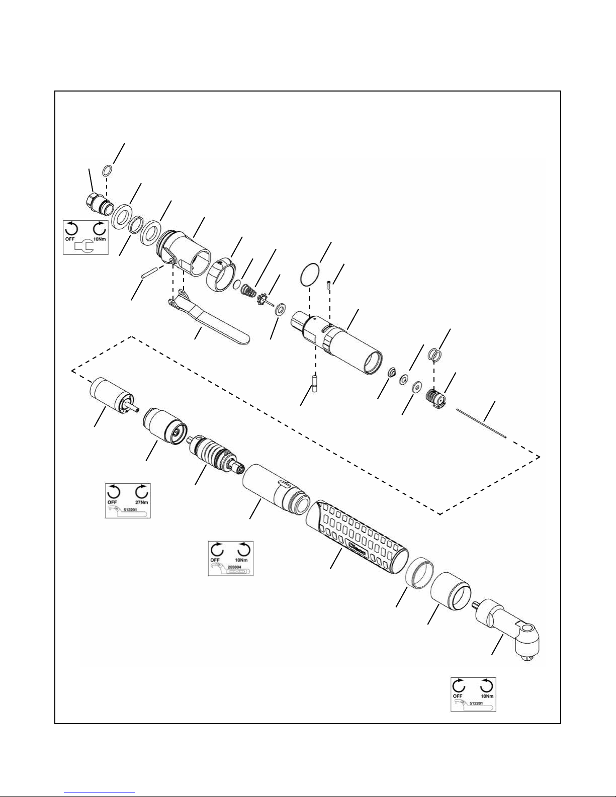
10.1 19RAA Series Nutrunner Models
19RAA02AM2
19RAA02AH(-)
19RAA03AM2
19RAA03AH(-)
19RAA04AM2
19RAA05AM(-)
19RAA06AH(-) *
19RAA07AH(-) *
19RAA09AH(-) *
19RAA11AH(-) *
19RAA12AH(-) *
Cleco®
Spare Parts
19
20
20
8
9
23 24
25
14
28
10
19
11
17
27
21
22
12 26
15 16
18
13
7
6
5
4
3
2
1
30
* Note: Maximum torque exceeds the
rated torque of the AH2 Angle Head.

Page 15
PL12-1014EN
10/16/2014
EN
Description
936566PT 1 Attachment (1/4" Square Drive)
936530PT 1 Attachment (1/4" Square Drive)
936531PT 1 Attachment (3/8" Square Drive)
201711 1 Attachment (5/16" Internal Hex)
302030PT 1 Attachment (Quick Change)
2 Table 10.1 1 Clutch Cover
3 207792PT 1 Plastic Body
4 207582PT 1 Clutch Housing
301982PT 1 Clecomatic Clutch Assembly
301992PT 1 Clecomatic Clutch Assembly
301978PT 1 Clecomatic Clutch Assembly
301967PT 1 Gearing Assembly
301086 1 Gearing Assembly
301968PT 1 Gearing Assembly
301969PT 1 Gearing Assembly
302016PT 1 Gearing Assembly
301970PT 1 Gearing Assembly
301972PT 1 Motor Assembly
301973PT 1 Motor Assembly
301974PT 1 Motor Assembly
8 205970 1 Exhaust Housing
9 205959 1 Reversing Ring
10 205967 1 Motor Housing
11 205984PT 1 Reversing Valve
12 203528PT 1 1 Lever
13 205968 1 1 Inlet Adapter
14 207035 1 3 O-Ring
15 205971 1 1 Actuator Pin
16 203525 1 3 Shut-Off Spring
17 203529 1 1 Shut-Off Valve
18 869201 1 3 Shut-Off Valve Seal
19 60351 3 9 O-Ring
20 205969 2 2 Bronze Muffler
21 205996 1 1 Muffler Spacer
22 844083 1 1 Lever Pin
23 869171 1 3 Screen
24 1001234 1 3 Compression Spring
25 01-2518 1 1 Poppet Valve
26 847675 1 3 Valve Seal
27 Table 10.1 1 1 Trip Rod
28 B141L 1 1 Screw
29 931962 1 1 Suspension Bail (not shown)
30 Table 10.1 1 Spacer
(#) Quantity
(X) Recommended Spare Parts (quantity shown based on 1-5 tools in operation)
10.1 19RAA Series Nutrunner
Ref Number # X
5
6
7
1
Cleco®
Spare Parts
Table 10.1
Ref. Description #
19RAA02AM2
19RAA02AH(-)
19RAA04AM2
19RAA06AH(-)
#
19RAA05AM(-)
19RAA07AH(-)
19RAA09AH(-)
19RAA12AH(-)
#19RAA03AM2
19RAA03AH(-) # 19RAA11AH(-)
2 Clutch Cover 1 207583PT 1 207583PT 1 207583PT 1 207703PT
27 Trip Rod 1 203586PT 1 203586PT 1 203586PT 1 207704PT
30 Spacer ---- 205974 1 205975PT 1 205974

Page 16
PL12-1014EN
10/16/2014
Models
19RAS02AH3
19RAS03AM2
19RAS04AH(-)
19RAS05AM2
19RAS06AH(-) *
Cleco®
Spare Parts
15
16
16
7
8
19 20
21
13
23
915
10
17
18
11 22
14
12
6
5
2
3
4
1
* Note: Maximum torque exceeds the
rated torque of the AH2 Angle Head.
26
25
10.2 19RAS Series Nutrunner

Page 17
PL12-1014EN
10/16/2014
EN
Description
936566PT 1 Attachment (1/4" Square Drive)
936530PT 1 Attachment (1/4" Square Drive)
936531PT 1 Attachment (3/8" Square Drive)
2 207792PT 1 Plastic Body
3 207367 1 Housing Adapter
4 207368 1 Spindle Extension
301967PT 1 Gearing Assembly
301086 1 Gearing Assembly
301968PT 1 Gearing Assembly
301972PT 1 Motor Assembly
301973PT 1 Motor Assembly
301974PT 1 Motor Assembly
7 205970 1 Exhaust Housing
8 205959 1 Reversing Ring
9 205967 1 Motor Housing
10 205984PT 1 Reversing Valve
11 203528PT 1 1 Lever
12 205968 1 1 Inlet Adapter
13 207035 1 3 O-Ring
14 205971 1 1 Actuator Pin
15 60351 3 9 O-Ring
16 205969 2 2 Bronze Muffler
17 205996 1 1 Muffler Spacer
18 844083 1 1 Lever Pin
19 869171 1 3 Screen
20 1001234 1 3 Compression Spring
21 01-2518 1 1 Poppet Valve
22 847675 1 3 Valve Seal
23 B141L 1 1 Screw
24 931962 1 1 Suspension Bail (not shown)
25 540843 1 3 Drive Screw
26 Table 10.2 1 Spacer
(#) Quantity
(X) Recommended Spare Parts (quantity shown based on 1-5 tools in operation)
10.2 RAS Series Nutrunner
Ref Number # X
1
6
5
Cleco®
Spare Parts
Table 10.2
Ref. Description #
19RAS02AH3
19RAS05AM2
19RAS06AH(-)
#19RAS03AM2
19RAS04AH(-)
26 Spacer ------ 1 205975PT

Page 18
PL12-1014EN
10/16/2014
Cleco®
Spare Parts
6
4
8
1
95
2
6
5
7
3
10.3 Motor Assembly

Page 19
PL12-1014EN
10/16/2014
EN
Description
-- Table 10.3 1 Motor Assembly
1 203504 1 Cylinder
2 205960 1 Rear Bearing Plate
3 Table 10.3 1 Rotor
4 203641 1 Front Bearing Plate
5 203615PT 4 12 Rotor Blade
6 842768 2 4 Ball Bearing
7 844897 1 2 Front Cylinder Pin
8 847548 1 2 Rear Cylinder Pin
9 Table 10.3 1 2 Pin
(#) Quantity
(X) Recommended Spare Parts (quantity shown based on 1-5 tools in operation)
10.3 Motor Assembly
Ref Number # X
Cleco®
Spare Parts
Table 10.3
Ref. Description #
19RAA04AM2
19RAA06AH(-)
19RAA12AH(-)
#
19RAA02AM2
19RAA02AH(-)
19RAA05AM(-)
19RAA07AH(-)
19RAA09AH(-)
#
19RAA03AM2
19RAA03AH(-)
19RAA11AH(-)
# 19RAS02AH3 # 19RAS03AM2
19RAS04AH(-) #19RAS05AM2
19RAS06AH(-)
-- Motor Assembly 1 301974PT 1 301972PT 1 301973PT 1 301972PT 1 301973PT 1 301974PT
3 Rotor 1 203546 1 203545 1 203547 1 203545 1 203547 1 203546
9 Pin ----- ----- ----- 1 92570018 1 92570018 1 92570018
Page 20
PL12-1014EN
10/16/2014
Cleco®
Spare Parts
1
5
6
Models
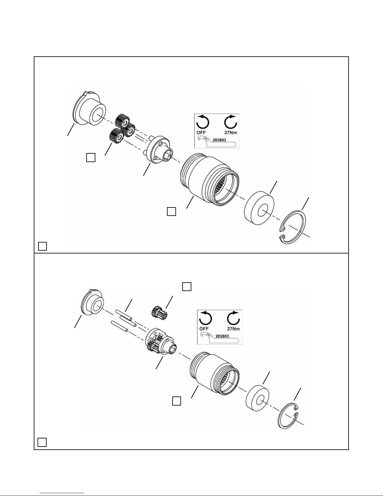
19RAA02AM2
19RAA02AH(-)
19RAS02AH3
Models
19RAA03AM2
19RAA03AH(-)
19RAS03AM2
19RAS04AH(-)
2
3
4
1
6
5
7
24
3
LLubricate with 540450 Grease (18 oz. can)
L
L
LLubricate with 540450 Grease (18 oz. can)
L
L
10.4 301967PT Gearing Assembly
10.5 301086 Gearing Assembly
This manual suits for next models
23
Table of contents
Other Cleco Nail Gun manuals


