Cleco 15ML-1.6B- 837 Troubleshooting guide

1
Printed in U.S.A. 12-1-97
OPERATING INSTRUCTIONS
AND
SERVICE MANUAL
15ML-1.6B- 837
FIXTURIZED NUTRUNNER
®
COMPLETE TOOL
MODEL NO. CODE NO.
15ML-1.6B-837 230837
READ SAFETY RECOMMENDATIONS BEFORE OPERATING TOOL
2
CAUTION!
Personal hearing protection is
recommended when operating
or working near this tool.
Safety Recommendations
Foryoursafetyandthesafetyofothers,readandunder-
standthesafetyrecommendationsandoperatinginstruc-
tions before operating any tool.
Always wear protective equipment:
For additional information on eye protection and face
protection,refer to FederalOSHA Regulations, 29Code
ofFederalRegulations,Section1910.133.,EyeandFace
Protection, and American National Standards Institute,
ANSIZ87.1,OccupationalandEducationalEyeandFace
Protection.Z87.1isavailablefromtheAmericanNational
StandardsInstitute,Inc.,11West42ndStreetNewYork,
NY. 10036.
Hearing protection is recommended in high noise areas
85 dBA or greater. The operation of other tools and
equipmentinthearea,reflectivesurfaces,processnoises
and resonant structures can substantially contribute to,
and increase the noise level in the area. Excessive air
pressureabove90PSIGor wornmotorcomponentscan
also increase sound level emitted by tool. For additional
informationonhearingprotection,refertoFederalRegu-
lations,Section 1910.95, Occupational NoiseExposure,
andAmericanNationalStandardsInstitute,ANSI S12.6,
Hearing Protectors.
Cleco tools are designed to operate on 90 psig (6.2 bar)
maximum air pressure. If the tool is properly sized and
applied, higher air pressure is unnecessary. Excessive
airpressureincreases theloadsandstresseson thetool
parts,sockets,andfastenersandmayresultinbreakage.
Installationofafilter-regulator-lubricator intheairsupply
line ahead of the tool is recommended.
Before the tool is connected to the air supply, check the
throttle for proper operation (i. e., throttle moves freely
and returns to closed position). Being careful not to
endangeradjacent personnel,cleartheairhoseofaccu-
mulated dust and moisture. Before removing a tool from
serviceorchangingsockets,makesuretheairlineisshut
off and drained of air. This will prevent the tool from
operating if the throttle is accidently engaged.
Some individuals may be susceptible to disorders of the
hands and arms when performing tasks consisting of
highly repetitive motions and/or exposure to extended
vibration. Cumulative trauma disorders such as carpal
tunnelsyndrome andtendonitiscanbecausedoraggra-
vated by repetitious, forceful exertions of the hands and
arms. Vibration may contribute to a condition called
Raynaud's Syndrome. These disorders develop gradu-
ally over periods of weeks, months, and years. It is
presentlyunknownto whatextentexposuretovibrations
or repetitive motions may contribute to the disorders.
Hereditary factors, vasculatory or circulatory problems,
exposuretocoldanddampness, diet, smoking and work
practices are thought to contribute to the conditions.
Anytool operator should beawareof the following warn-
ing signs and symptoms so that a problem can be
addressedbeforeitbecomesadebilitatinginjury.Anytool
operator should be aware of the following warning signs
and symptoms so that a problem can be addressed
beforeitbecomesadebilitatinginjury.Anyusersuffering
prolongedsymptomsoftingling,numbness,blanchingof
fingers, clumsiness or weakened grip, nocturnal pain in
the hand, or any other disorder of the shoulders, arms,
wrists, or fingers is advised to consult a physician. If it is
determined that the symptoms are job related or aggra-
vated by movements and postures dictated by the job
design,itmaybenecessaryfortheemployertotakesteps
to prevent further occurrences. These steps might in-
clude, but are not limited to, repositioning the workpiece
or redesigning the workstation, reassigning workers to
other jobs, rotating jobs, changing work pace, and/or
changingthetypeoftoolusedsoastominimizestresson
theoperator.Sometasksmayrequiremorethanonetype
of tool to obtain the optimum operator/tool/task relation-
ship.
WARNING!
Impact resistant eye protection
must be worn while operating
or working near this tool.
Repetitive work motions and/or vibration
can cause injury to hands and arms.
Use minimum hand grip force consistent
with proper control and safe operation.
Keep body and hands warm and dry.
Avoid anything that inhibits blood circulation.
Avoid continuous vibration exposure.
Keep wrists straight.
WARNING
!
Avoid repeated bending of wrists and hands.

3
Safety Recommendations
The following suggestions will help reduce or moderate
the effects of repetitive work motions and/or extended
vibration exposure:
•Use a minimum hand grip force consistent with
proper control and safe operation
•Keep body and hands warm and dry (cold
weather is reported to be a major factor contrib
uting to Raynaud's
Syndrome)
•Avoid anything that inhibits blood circulation
—Smoking Tobacco (another contributing
factor)
—Cold Temperatures
—Certain Drugs
•Tasks should be performed in such a manner
that the wrists are maintained in a neutral posi-
tion, which is not flexed, hyperextended, or
turned side to side.
•Stressful postures should be avoided —select
a tool appropriate for the job and work location
•Avoid highly repetitive movements of hands
and wrists, and continuous vibration exposure
(after each period of operation, exercise to
increase blood circulation)
•Keep tool well maintained and replace worn
parts
Work gloves with vibration reducing liners and wrist sup-
portsareavailablefromsomemanufacturersofindustrial
workgloves.Toolwrapsandgripsarealsoavailablefrom
anumberofdifferentmanufacturers.Thesegloves,wraps,
and wrist supports are designed to reduce and moderate
the effects of extended vibration exposure and repetitive
wrist trauma. Since they vary widely in design, material,
thickness,vibrationreduction,andwristsupportqualities,
it is recommended that the glove, tool wrap, or wrist
support manufacturerbeconsultedforitemsdesignedfor
yourspecificapplication.WARNING!Properfitofgloves
is important. Improperly fitted gloves may restrict
bloodflowtothefingersandcansubstantiallyreduce
grip strength.
Abooklet,AssemblyToolErgonomics,isavailablefreeof
charge by writing the following address:
Industrial Tool Division
P. O. Box 40430
Houston, Texas 77240 USA
713/462-4521
Please request Form No. 60669.
Formoreinformationonthesafeuse ofportableairtools,
see the latest edition of ANSI B186.1, Safety Code for
Portable Air Tools, available from the American National
Standards Institute, Inc. 11 West 42nd Street New York,
NY. 10036.
Warning Labels
The warning labels found on these tools are an essential
partofthisproduct.Labelsshouldnotberemoved.Labels
shouldbecheckedperiodicallyforligibility.Replacewarn-
ing labels when missing or when the information can no
longer be read. Replacement labels can be ordered as
any spare part.
Extension Neutral Flexion Radial Deviation Neutral Ulnar Deviation
Avoid Avoid Avoid
OK Avoid OK

4
OPERATION
The tools are designed to operate on 90 PSIG (6.2 bar) air
pressure. The 15ML series requires a 3/8" hose.
The 15ML series is started by depressing the lever and
stopped by releasing the lever.
LUBRICATION
An automatic in-line filter-lubricator is recommended as it
increasestoollifeandkeepsthetoolinsustainedoperation.
Thein-line lubricator shouldbe regularly checked and filled
withagoodgradeof10Wmachineoil.Properadjustmentof
thein-linelubricatorisperformedbyplacingasheetofpaper
next to the exhaust ports and holding the throttle open
approximately 30 seconds. The lubricator is properly set
when a light stain of oil collects on the paper. Excessive
amounts of oil should be avoided.
In the event that it becomes necessary to store the tool for
an extended period of time (overnight, weekend, etc.), it
shouldreceivea generousamountof lubricationatthattime
and again when returned to service. The tool should be
stored in a clean and dry environment.
Allothergearsandopenbearingsshouldreceiveagenerous
amountofShell#65115Maleuscompoundduringassembly.
After completing assembly of the gear case, and prior to
assembling it with the motor and motor housing, additional
Shell lubricant must be added until the gear case cavity is
approximately 2/3 full. Do not overfill.
FOR YOUR SAFETY AND THE SAFETY OF OTHERS READ AND UNDERSTAND THE SAFETY
RECOMMENDATIONS BEFORE OPERATING TOOL.
OPERATING INSTRUCTIONS
5
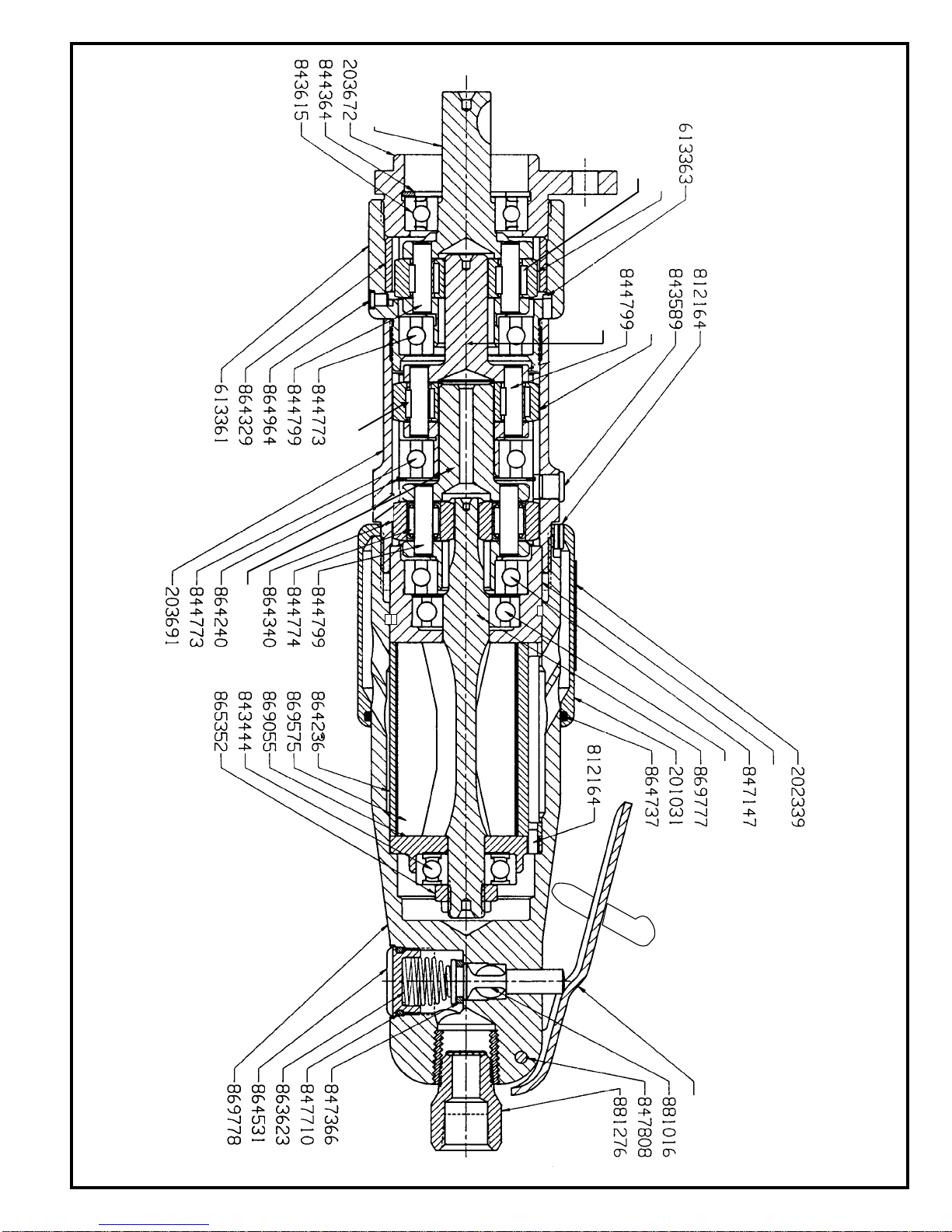
SERVICE INSTRUCTIONS
DISASSEMBLY
Thetool should beclamped in the visewith the geartrain in
a vertical position. Using a suitable wrench, unscrew the
gear case and slip the motor out of the motor housing.
NOTE: On the double reduction tools, the first reduction
spider will remain with the motor and should be removed at
this time. This completes the disassembly of the tool into
three (3) major subassemblies (Gear Case, Motor, and
MotorHousing). Seethefollowingparagraphsforcomplete
disassembly instruction.
GEARCASE:HoldingthesecondgearcaseNo.613361,in
the vise, unscrew bearing retainer No. 203672. Drive third
reductiongearspiderNo.204623,outofbearingNo.843615.
Unscrew second gear case No. 613361, from gear case.
Thesecondreduction spiderassemblymaybepressedout
therearofthegearcase,No.203691,aftertheretainerring,
No. 864240, is removed from the inside of the gear case.
After the spider bearings have been removed, using a
suitable bearing puller, the idler gears may be removed for
inspection by driving the idler gear pins out the rear of the
spiders.
MOTOR:Usingasoft-facedmallet,drivetherotoroutofthe
front rotor bearing, No. 619991. This will allow the removal
ofthefrontbearingplate,No.865344,cylinder,No.864236,
and rotor blades, No. 869575. After removing the rotor lock
nut, No. 865352, from the rear rotor shaft, the rotor may be
driven out of the rear rotor bearing, No. 843444.
MOTORHOUSING:Thethrottlevalve,No.869350,usedin
the pistol grip handle may be removed for inspection by
unscrewing the inlet bushing, No. 833471. The lever back-
head throttle valve seal, No. 847366, may be removed by
unscrewing the throttle valve cap, No. 864531.
Unscrew the inlet bushing, No. 881276, for inspection and
cleaning of the air screen on the lever backhead.
REASSEMBLY
The tool is reassembled in the reverse of disassembly. All
parts should be thoroughly cleaned and inspected for wear
beforereassembly.Replaceallbearingswhichfeelroughor
haveexcessiveendplay.ThesealsonbearingNo.619991
andNo.843615shouldbecheckedclosely andthebearing
shouldbereplaced if visibledamageisevidenttothe seals.
All other gears and open bearings should receive a gener-
ous amount of Shell #65115 Maleus compound during
assembly.Aftercompleting assemblyofthegearcase, and
prior to assembling it with the motor and motor housing,
additionalShelllubricant must be added untilthegear case
cavity is approximately 2/3 full. Do not overfill.
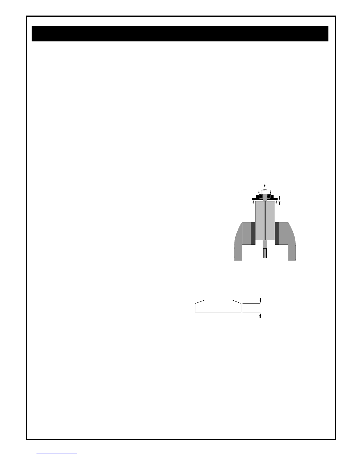
Toassemblethemotor,installtherearrotorbearingintothe
rearbearingplate.Makesuretheouterbearingraceisfirmly
seatedinthebearingplate.Clamptherotorbodylightlyinthe
visewiththethreadedendupandsliptherearbearingplate
assemblyontotherotorshaftfarenoughfortherotorlocknut
to start. Tighten the lock nut until there is approximately
.0015" (.038mm) clearance between the rotor and bearing
plate.Theouterbearingraceshouldbefirmlyseatedandthe
rotor bumped forward when checking this clearance.
Itisrecommendedthatnewrotorbladesbeinstalledateach
repaircycle.Ifnotreplaced,theusedones must measure a
minimum of 7/32" (5.5mm) at both ends.
The front motor bearing is sealed, so it cannot be packed
withgreased. The rearrotor bearing shouldbe packed with
a good grade of NLGI 2-EP grease after assembly of the
motor unit.
During assembly of the gear case to the motor and motor
housing, be sure that the teeth of the rotor mesh with the
teeth of the idler gears. Rotate the gear train by hand to be
sure the teeth are properly meshed before air is applied.
FOR YOUR SAFETY AND THE SAFETY OF OTHERS READ AND UNDERSTAND THE SAFETY
RECOMMENDATIONS BEFORE SERVICING TOOL.
SOFT
JAWED
VISE
.0015"
Clearance
Must be replaced if
7/32" (5.5mm) or less
at either end.

6
201031-2
202339-8
203672-1
203691-1
204623-3
204631-6 *
204632-4 †
613361-5
613363-4
619991-3
812164-2
843444-1
843615-6
844364-0
844773-2
844774-0 * †
844799-7 * †
847147-6
847366-2
847710-1
847808-3
861992-6
863623-5
864236-5
864240-7
864323-1 *
864329-8
864340-5 †
864531-9
864737-2
864964-2
865344-6
865352-9
869055-4
869575-1
869777-3
869778-1
881016-0
881276-0
1s
1
1
1
1
1
1
1
1
1
1
1
1
1
2
6
6
1
1
1
1
1
1
1
1
4
1
2
1
1
1
1
1
1
4
1
1
1
1
EXHAUST DEFLECTOR
SAFETY LABEL
BEARING RETAINER
GEAR CASE
3RD RED. SPIDER
2ND. RED. SPIDER (14T)
1ST. RED. SPIDER (14T)
GEAR CASE
PIN, DOWEL
BEARING, BALL
PIN, ROLL
BEARING, BALL
BEARING, BALL
RETAINER RING
BEARING, BALL
IDLER GEAR BEARING
PIN
BEARING, BALL
THROTTLE VALVE SEAL
"O"RING
PIN, GROOVE
LOCK-OFF LEVER
SPRING, THROTTLE VALVE
CYLINDER
BEARING RETAINER
2ND. & 3RD. RED. IDLER GEAR (16T)
GEAR, RING
1ST. RED. IDLER GEAR (18T)
CAP
"O"-RING
GREASE FITTING
FRONT BEARING PLATE
NUT, LOCK
REAR BEARING PLATE
ROTOR BLADE
ROTOR
BACKHEAD
VALVE, THROTTLE
BUSHING
PARTNO. NAME OF PARTS QTY.
* PARTS INCLUDED IN 2ND. RED. SPIDER SUBASSEMBLY — 201767
† PARTS INCLUDED IN 1ST. RED. SPIDER SUBASSEMBLY — 201766
7
865344
619991
204632
864323
204631
864323
204623
861992
844774
844774
This manual suits for next models
1
Table of contents
Other Cleco Nail Gun manuals


