Cleerline SSF-1x4POE-RUGGED User manual

SSF-1x2-RUGGED / SSF-1x4-RUGGED / SSF-1x4POE-RUGGED
Industrial Ethernet Switch
Manual
www.cleerlineber.com

Industrial Ethernet Unmanaged
2
INDUSTRIAL ETHERNET SWITCHES
Ordering Information
SSF-1x2-RUGGED Gigabit Ethernet Switch 2x 10/100/1000Base-Tx to
100/1000Base-X SFP slot, PoE+ 60W budget DIN rail and wall installation.
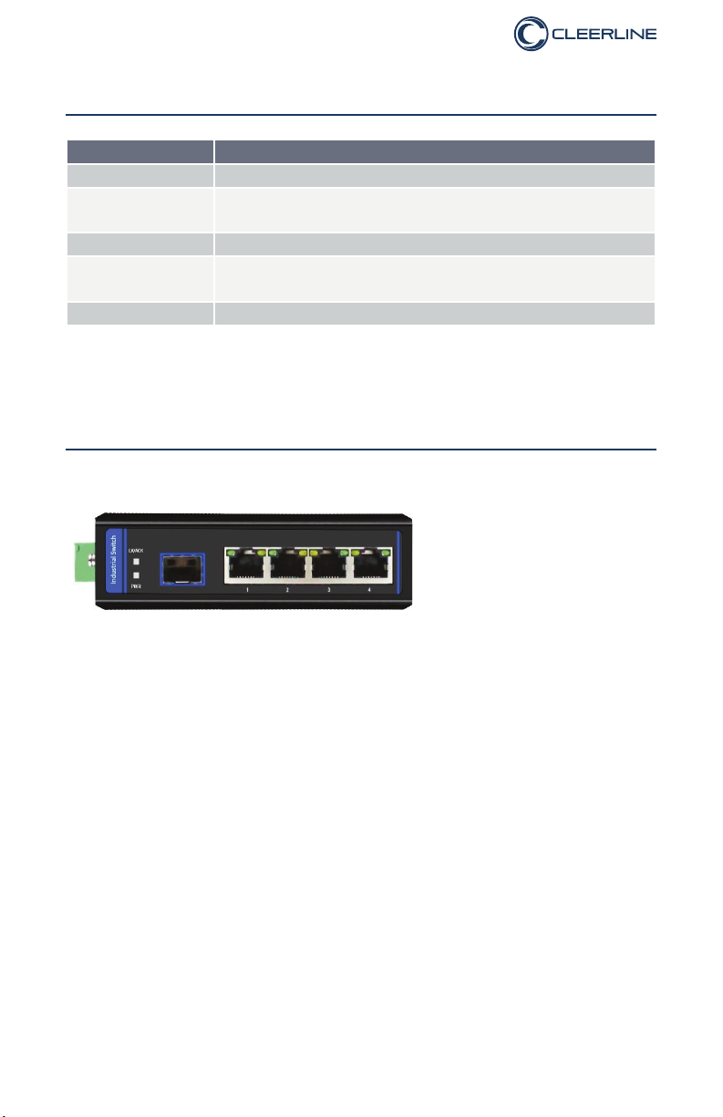
SSF-1x4-RUGGED Gigabit Ethernet Switch 4x 10/100/1000Base-Tx + 1x
100/1000Base-X SFP slot ports, DIN rail and wall installation
SSF-1x4POE-RUGGED Gigabit Ethernet Switch 4x 10/100/1000Base-Tx to
100/1000Base-X SFP slot, PoE+ 120W budget DIN rail and wall installation.
Overview
The Industrial Ethernet models listed above are high performance and reliable
Ethernet switches. All Industrial models are hardened for -40 to +75°C operation
and have 6kV surge protection on all ports. All PoE models deliver 30W per each
UTP port supporting 802.3at PoE+ standard. Reliability is highly ranked with
an MTBF exceeding 120,000 hours. All Industrial Ethernet models listed in this
manual have passed IEC standards as described in the Technical Specications
table.
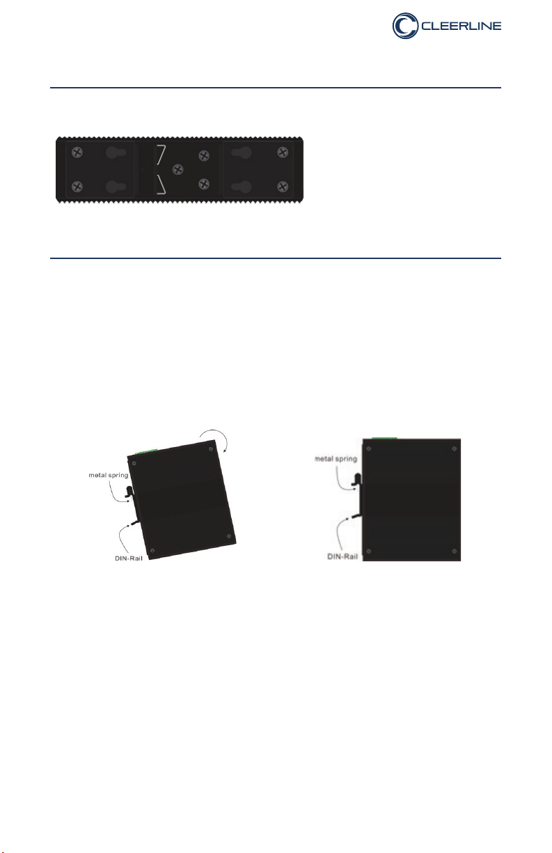
Package includes DIN rail mounting bracket, wall bracket, screw block power
connector and one User Manual.
Features
• IEEE 802.3 10Base-T, 802.3u 100Base-TX, 802.3z 1000Base-T, 802.3af
and 802.3at support
• Auto-Negotiation and Auto MDI/MDIX
• 6kV Ethernet surge protection on all TP ports
• Full-duplex and Half-duplex ow control modes
• Auto PoE detection for connected PD devices
• 15.4W PoE power for IEEE 802.3af and 30W PoE power for IEEE 802.3at
standard for each copper port (PSE models only)
• Store and Forward switching mechanism
• Extreme -40 ~ +75°C operating temperature
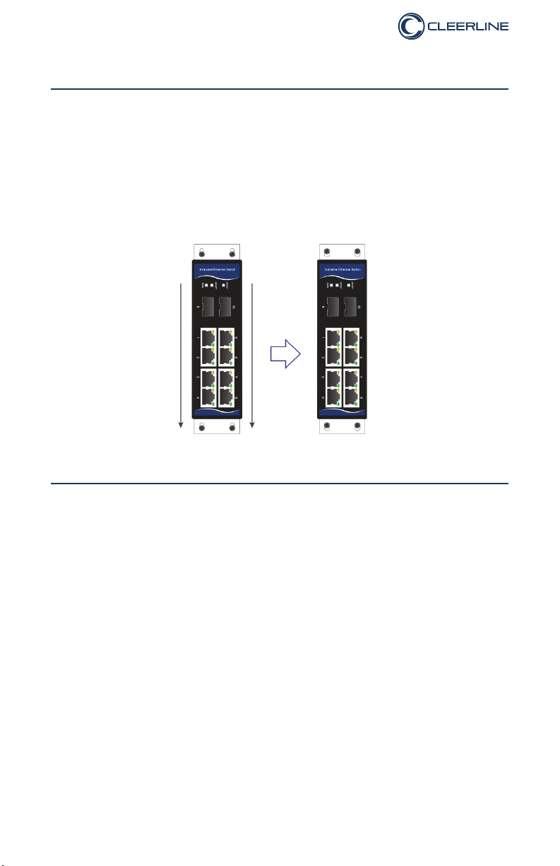
• DIN rail or Wall mount installation options, IP40 rated housing
• 9-52V DC wide power input (48-52V DC for PoE PSE models)

Industrial Ethernet Unmanaged
3
Technical Specications by Model
MODEL SSF-1X2-RUGGED SSF-1X4-RUGGED SSF-1X4RUGGED-POE
TP ports
(RJ45) 2 x 10/100/1000 4 x 10/100/1000 4 x 10/100/1000
SFP slots 1 x 100/1000 1 x 100/1000 1 x 100/1000
LEDs
Network
Protocols CSMA/CD CSMA/CD CSMA/CD
Bandwidth 10G 10G 10G
Packet buffer
size 1M 1M 1M
Packet max.
size (bytes) 10K 10K 10K
MAC address
table size 4K 4K 4K
Safety CE/LVD EN60950 CE/LVD EN60950 CE/LVD EN60950
Power input DC 48~52V DC 9~56V/DC5V DC 48~52V
Reverse
Polarity
Protection
Yes Yes Yes
PoE budget 60W None 120W
Max PoE
power per port 30W n/a 30W
Mounting DIN
rail bracket Yes Yes Yes
Mounting Wall
bracket Yes Yes Yes
Operating
Temp (°C) -40 ~ +75 -40 ~ +75 -40 ~ +75
Storage Temp
(°C) -50 ~ +85 -50 ~ +85 -50 ~ +85
Operating
Humidity
10 ~ 90% non-
condensing
10 ~ 90% non-
condensing
10 ~ 90% non-
condensing
Dimensions
(mm) * 120x 88x 35 138x 108x 49 120x 88x 35
Weight (g)
MTBF 120,000 hours 120,000 hours 120,000 hours
Warranty 2 years 2 years 2 years
* dimensions are taken with no SFPs inserted, nor power block connectors

Industrial Ethernet Unmanaged
4
Industrial Compliance by Model
MODEL SSF-1X2-RUGGED SSF-1X4-RUGGED SSF-1X4RUGGED-POE
EMI
FCC Part 15 Subpart
B Class A, EN 55022
Class A
FCC Part 15
Subpart B Class A,
EN 55022 Class A
FCC Part 15 Subpart
B Class A, EN 55022
Class A
EMS
EN 61000-4-2 (ESD) Level 3 Criteria B, EN 61000-4-3 (RS) Level
3 Criteria A, EN 61000-4-4 (EFT) Level 3 Criteria A, EN 61000-4-5
(Surge) Level 3 Criteria B, EN 61000-4-6 (CS) Level 3 Criteria A, EN
61000-4-8(PFMF, Magnetic Field) Field Strength 300A/m Criteria A
Vibration IEC 60068-2-6 IEC 60068-2-6 IEC 60068-2-6
Freefall IEC 60068-2-32 IEC 60068-2-32 IEC 60068-2-32
Shock IEC 60068-2-27 IEC 60068-2-27 IEC 60068-2-27
Rail Trafc EN 50121-4 EN 50121-4 EN 50121-4
Trafc Control NEMA-TS2 NEMA-TS2 NEMA-TS2

Industrial Ethernet Unmanaged
5
LED Indicators (markings will vary with models)
FUNCTION
PWR Off – No power available; On – Power is present
Fiber LK/ACT LINK Off – No link; On – Fiber link OK;
Blinking – data trafc present
UTP GREEN Off – 10M/100M; On – 1000M on RJ45 port
UTP YELLOW Off – No link; On – UTP link OK;
Blinking – data trafc present
SYS Off – Switch failed; On – Switch operating normally
Note: Gigabit models require approx. 10 seconds from “Power On” to start operating
Switch Front Plate View
(common front view, may vary with model) Models
SSF-1x2-RUGGED
SSF-1x4-RUGGED
SSF-1x4POE-RUGGED

Industrial Ethernet Unmanaged
6
Top Panel View
(Common top view, may vary with model) Models
SSF-1x2-RUGGED
SSF-1x4-RUGGED
SSF-1x4POE-RUGGED
Top panel has terminal screw block for PWR1 and PWR2 input as well as Alarm
Relay output, alternate DC5V power jack and M3 grounding screw.
Alarm Relay Wiring
The alarm relay is closed during normal operation. If a fault is
encountered (like power supply input lost) then relay contacts
open until fault is remedied
Power input wiring
There are two independent and redundant power inputs,
marked PWR1 and PWR2. Observe voltage polarity when
wiring power to the screw block connector. Complete
wiring without hot wires and with screw block connector
disconnected from switch.
Installation Warning
Ensure proper electrical grounding availability before powering up device. The
unit should be grounded using either the M3 grounding screw or with the DIN rail
installation or wall mount brackets correctly grounded. Make sure power wires
have adequate gauge for the power required by the unit to avoid risk of wires
overheating and/or re. This is especially important for the PoE PSE equipment.
As general rule, keep power wiring on a different path from data cables and avoid
crossing wires. This will reduce the risk of power surges on data ports.

Industrial Ethernet Unmanaged
7
Rear Panel View with DIN rail and Wall Mounting Brackets
(common rear view, may vary with model) Models
SSF-1x2-RUGGED
SSF-1x4-RUGGED
SSF-1x4POE-RUGGED
DIN Rail Mounting Procedure
All Industrial switches from the SSF-RUGGED series have DIN rail bracket mounted
from factory to the rear panel of the unit. If wall mounting is needed, rst remove
the DIN rail bracket. If DIN rail bracket needs to be reattached, make sure the
spring is located on top position when unit is vertical.
Step 1 Step 2
Hold unit as in below image, making
sure top of bracket with spring falls
onto the top edge of TS-35 DIN rail.
Rotate and snap the unit onto the DIN
rail by pushing the bottom unto the TS-
35 DIN rail. Unit will be secured to rail.
To remove unit from rail, repeat procedure in reverse. Start by pulling out the
bottom of unit from the DIN rail.

Industrial Ethernet Unmanaged
8
Wall Mounting Procedure
All Industrial switches from the SSF-RUGGED series have DIN rail bracket
mounted from factory to the rear panel of the unit. If wall mounting is needed, rst
remove the pre-installed DIN rail bracket.
Secure the wall mounting brackets to the switch as in the below diagram. You will
need 4x M3 screws for the wall mounting brackets (included) and screws for wall
securing that should have head diameter larger than 6mm and screw body less
than 3.5mm (these screws are not included in the package).
Warning
1. Use only indoors in climate-controlled environments.
2. Avoid looking directly into bers or lasers while unit is powered.
3. 9-52V DC wide power input (48-52V DC for PoE PSE models) - not included.
FCC and CE markings
This equipment has been tested and found to comply with the limits for a Class
B digital device, pursuant to part 15 of the FCC Rules. These limits are designed
to provide reasonable protection against harmful interference in a residential
installation. This equipment generates, uses and can radiate radio frequency
energy and, if not installed and used in accordance with the instructions, may
cause harmful interference to radio communications.
This is a CE class B device, intended to be used in residential, commercial or
industrial applications.
This manual suits for next models
2
Table of contents