Clemas & Co i-air PRO Quick start guide

2
Original service manual, written in the English Language
Future Cleaning Technologies B.V.
Hoppenkuil 27b, 5626 DD Eindhoven, The Netherlands
Telephone: +31402662400
Email: hello@i-teamglobal.com
Internet: www.i-teamglobal.com
Model: I-AIR PRO
Date: 02/12/2020
Product code: I-AIR PRO.2020.01
Version: v.2.0

3
Introduction
This is the service manual for the i-air Pro®, the stand alone indoor air purification system.
When this manual refers to "the manufacturer" this means: Future Cleaning Technologies B.V., an
affiliate company of i-team in Eindhoven, the Netherlands. When this manual mentions "the
partner", your local i-team resell and support service partner is referred to.
Target group
This service manual addresses all technicians who install and maintain the i-air Pro. The service and
repair of the cleaning circuit and electrical system of the i-air is to be done only by a qualified service
and repair engineer. Failure to do so can result in personal injury or equipment damage. Read the
entire manual before the initial start-up of the air purification system. It is important to know the
correct procedures and all safety precautions to prevent the possibility of personal injury and/or
property damage.
Warranty claims
Using a device outside the specified conditions and contrary to its designated use will lead to the
forfeiture of all warranty claims.
Reservation
Future Cleaning Technologies B.V. reserves the right to make changes and improvements to the
product and the service manual at any time without prior notice or obligation.
Copyright
Copying of this service manual, or part of it, is forbidden without prior written permission from
Future Cleaning Technologies B.V.
Recycling
The unit is designed to last for many years. When the time comes for the unit to be recycled, the unit
should be recycled according to national regulation to protect the environment.

4
Identification
Each i-air Pro® has a unique identification number that can be found on the back side of the unit, in
the left lower corner. You need this number when you order parts.
Explanation type plate:
Product type: i-air Pro
Serial number: I-AIR.2020.05
Power supply and capacity: AC 220 V 500 W
Manufacturer: TCO Sp. z o.o.
Country of assembly: Poland
Figure 1
Reading guide
The following symbols and terms are used throughout this manual to alert the reader to
safety issues and important information:
Symbol
Term
Explanation
WARNING
Indicates a hazardous situation which, if the safety
instructions are not followed, can lead to injuries of the
operator or bystanders, light and/or moderate damage
to the product or the environment.
CAUTION
Indicates a hazardous situation which, if the safety
instructions are not followed, can lead to light and/or
moderate damage to the product or the environment.
ATTENTION
Indicates a liability situation, where the manufacturer
or its partners and affiliates cannot be held accountable
for damages caused by non-compliance.

5
Content
Introduction........................................................................................................................................................3
Target group...................................................................................................................................................3
Warranty claims..............................................................................................................................................3
Reservation.....................................................................................................................................................3
Copyright........................................................................................................................................................3
Recycling ........................................................................................................................................................3
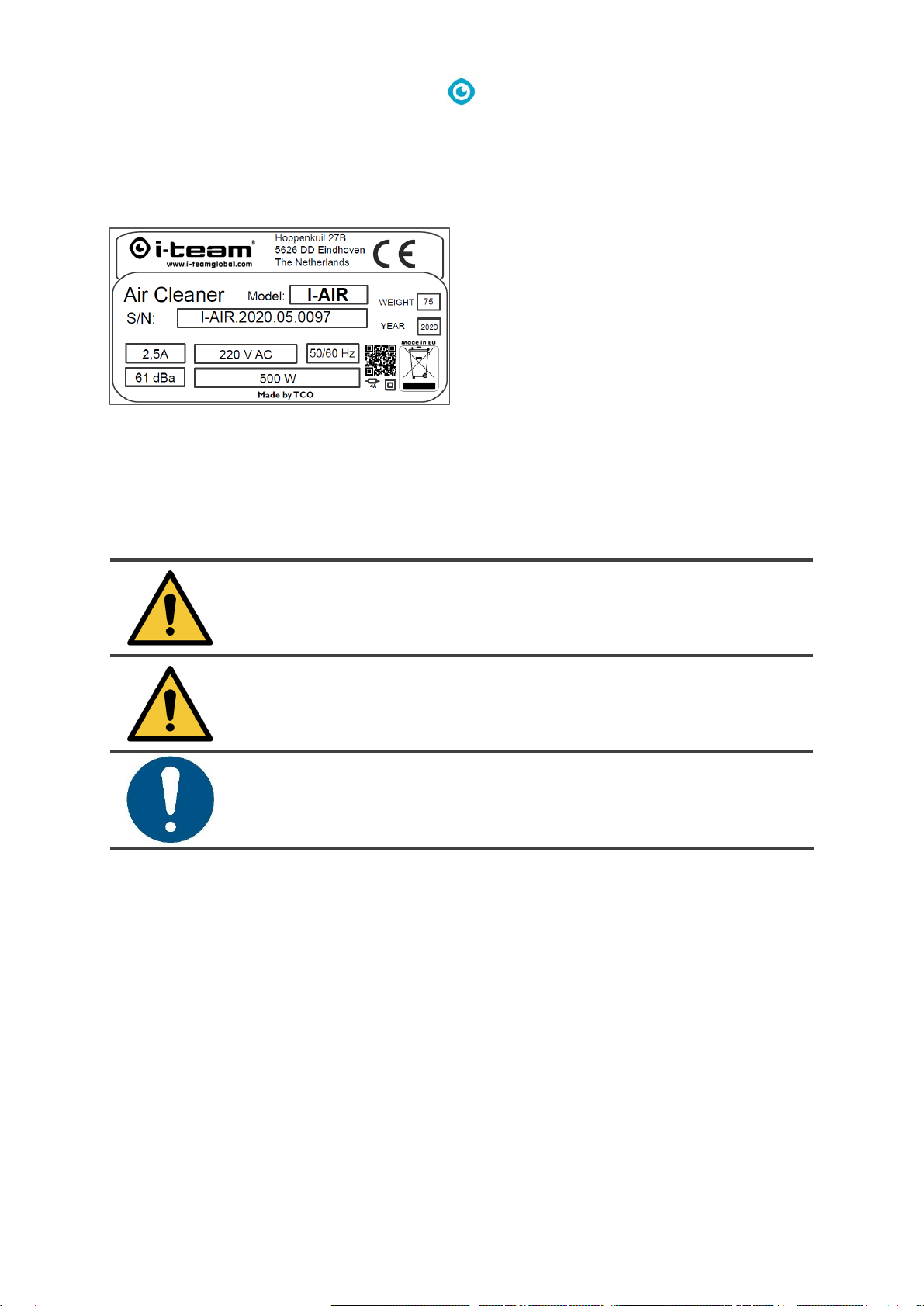
Identification ..................................................................................................................................................4
Reading guide.................................................................................................................................................4
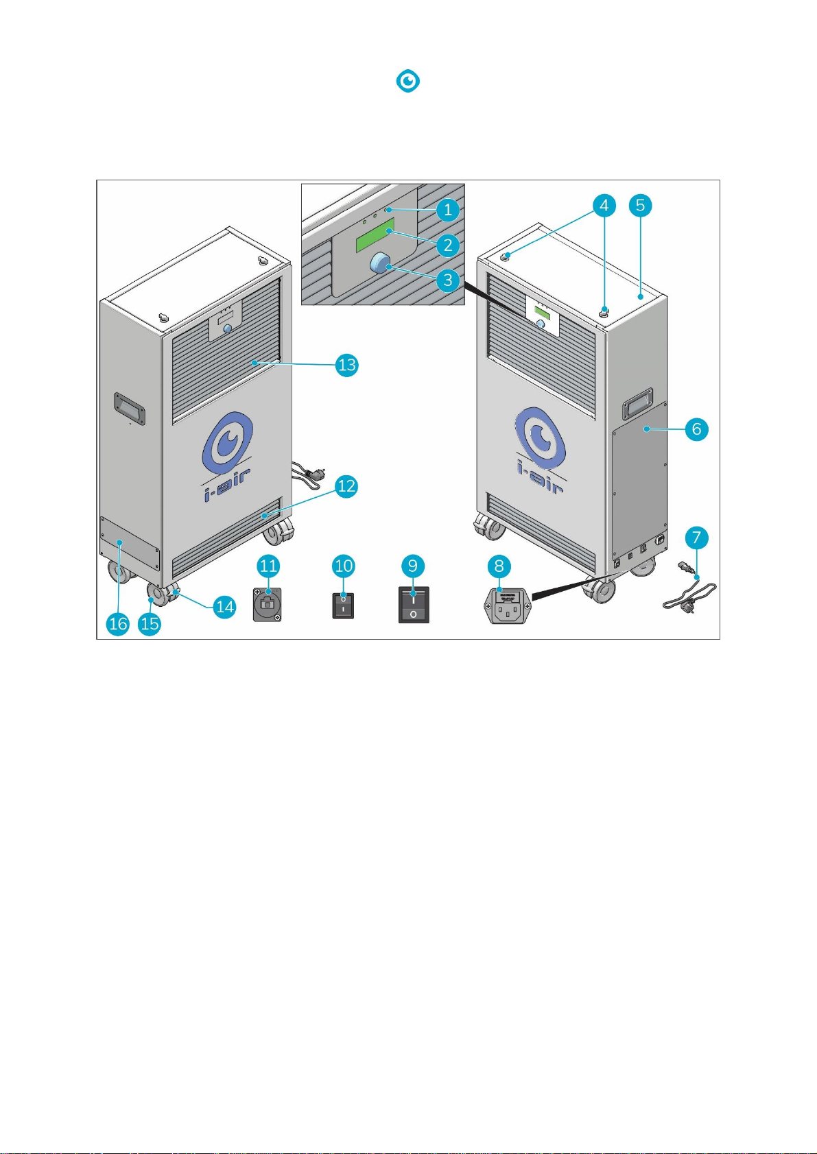
1Description.................................................................................................................................................7
1.1 Working principle...............................................................................................................................8
2Safety .........................................................................................................................................................9
2.1 General safety instructions ................................................................................................................9
3Installation ...............................................................................................................................................10
3.1 Location...........................................................................................................................................10
3.2 Transportation.................................................................................................................................10
3.3 Electrical connection........................................................................................................................10
3.4 Main power on/off...........................................................................................................................10
3.5 Front logo lighting on/off .................................................................................................................11
4Access to settings, values and error codes................................................................................................12
4.1 Control panel ...................................................................................................................................12
4.1.1 Using the control panel................................................................................................................12
4.2 Control panel menus........................................................................................................................13
4.2.1 Fan menu.....................................................................................................................................13
4.2.1.1 Fan level..............................................................................................................................13
4.2.1.2 Fan mode ............................................................................................................................13
4.2.2 Schedule menu ............................................................................................................................13
4.2.2.1 Schedule..............................................................................................................................14
4.2.3 Sensors menu ..............................................................................................................................14
4.2.3.1 Sensors................................................................................................................................14
4.2.4 Lamps menu ................................................................................................................................14
4.2.4.1 Lamp on time ......................................................................................................................15
4.2.5 Settings menu..............................................................................................................................16
4.2.5.1 Date and time......................................................................................................................16
4.2.5.2 Ethernet ..............................................................................................................................17
4.2.5.3 User web password.............................................................................................................17
4.2.5.4 Service settings ...................................................................................................................17
4.2.6 Status menu.................................................................................................................................18
4.2.6.1 Status..................................................................................................................................18
4.3 Factory reset....................................................................................................................................18
4.4 WWW interface ...............................................................................................................................18

6
5Service......................................................................................................................................................19
5.1 Power supply module ......................................................................................................................19
5.1.1 Replace power supply subassemblies ..........................................................................................20
5.1.2 Adjustment and setting of power supply module.........................................................................20
5.2 UV module.......................................................................................................................................21
5.2.1 Replace UV subassemblies...........................................................................................................21
5.3 Fan module......................................................................................................................................22
5.3.1 Replace fan module .....................................................................................................................23
5.4 Electronic module ............................................................................................................................23
5.4.1 Replace electronic module...........................................................................................................25
5.5 Filter replacement............................................................................................................................25
5.5.1 Replace the carbon pre-filter .......................................................................................................25
5.5.2 Replace the HEPA H14 main filter ................................................................................................ 25
5.6 Preventive maintenance schedule....................................................................................................25
6Fault finding guide....................................................................................................................................27
7Technical information...............................................................................................................................28
7.1 Technical specifications....................................................................................................................28
7.2 Specification ....................................................................................................................................29
7.2.1 Enclosure dimensions ..................................................................................................................29
7.3 Spare parts.......................................................................................................................................30
7.4 Wiring diagrams...............................................................................................................................45
8CE certificate ............................................................................................................................................49

7
1Description
The i-air Pro® combines state-of-the-art air purifying technologies in one, easy to set up stand-alone
unit. The i-air Pro consists of:
1. LED indicators.
2. Display.
3. Operation knob.
4. Locking knobs of main HEPA filter compartment lid.
5. Main HEPA filter compartment. Attached to the inside of the compartment panel you will find
a 2.5 Allen wrench, to be used for opening the panel of the pre-filter compartment.
6. Neutralization chamber panel.
7. Power cable.
8. Power cable socket.
9. Main power on/off switch.
10. Front logo lighting on/off switch.
11. RJ-45 ethernet connection socket.
12. Air inlet.
13. Air outlet.
14. Caster wheel brake.
15. Caster wheel.
16. Pre-filter compartment.
Figure 2

8
1.1 Working principle
The polluted air enters the air inlets at the front
and bottom of the unit (Figure 3, pos. 5). The air
is drawn in by a fan (Figure 3, pos. 2) installed in
the top of the unit.
The air passes through the custom designed
carbon pre-filter (Figure 3, pos. 4). The
carbon pre-filter filters out larger particles and
heavy dust. The layers of activated carbon in the
carbon pre-filter provide basic absorption of
volatile organic compounds.
The neutralization chamber (Figure 3, pos. 3) is
equipped with a UV module that takes care of
the volatile organic compounds and micro-
biological contamination.
The decontaminated air finally passes through a
high grade, custom made HEPA H14 main filter
(Figure 3, pos. 1). This filter ensures proper
filtration of the smallest particles (even smaller
than 0,3µ). The clean air leaves the unit through
the clean air outlet (Figure 3, pos. 6) on the front
of the i-air Pro® unit.
For further technical details see section 7.1.
1. HEPA H14 main filter.
2. Fan.
3. Neutralizing chamber.
4. Carbon pre filter.
5. Contaminated air inlets.
6. Clean air outlet.
7. Dust and VOC sensors.
Figure 3

9
2Safety
Safety comes first, therefore please take time to read and understand these safety instructions.
Improper use can cause harm or void the manufacturer’s warranty.
Work on the internal components may only be carried out by the manufacturer or personnel
authorized by the manufacturer. This work involves danger of electric shock, burns, crushing,
entanglement and cutting.
2.1 General safety instructions
The i-air Pro® is an electrical appliance. Please read the safety instructions before use and take the
necessary precautions to reduce the risk of fire, electric shock or injury.
•always use the replacement parts recommended by i-team Professional b.v.;
•always switch off and unplug the unit before replacing parts;
•always place the i-air Pro in an upright position with the brakes on the front caster wheels locked
when performing maintenance and repair tasks.
CAUTION
The i-air Pro unit is heavy. DO NOT try to carry and/or move the unit by yourself.
You should always use someone's help.

10
3Installation
The i-air Pro® does not require assembly. The carbon pre-filter and HEPA H14 main filter are pre-
installed.
3.1 Location
The i-air is for indoor use only. The machine is designed for commercial use in medium to large
spaces (up to 500 m2). The actual space coverage will depend on contamination level.
3.2 Transportation
Always place the i-air Pro in an upright position. Once correctly placed on location, always lock the
brakes on the front caster wheels when the i-air Pro is in operation.
CAUTION
Always keep the body of the i-air Pro in an upright position when moving it.
3.3 Electrical connection
The following items must be checked prior to electrical connection of the i-air Pro:
•is the main voltage in conformity with the voltage of the device;
•are the socket and supply system sufficiently fused;
•is the socket outlet used grounded properly.
3.4 Main power on/off
1. Insert the power cable into the power cable
socket of the i-air Pro (Figure 4, pos. 1) and
the power plug (Figure 4, pos. 2) into the
wall socket.
•The main power switch
(Figure 4, pos. 3) is in off position, the
red LED indicator in the switch is off.
2. Press the main power switch
(Figure 4, pos. 3) to turn on/off the power.
•The red LED indicator in the switch is
lit/off.
Figure 4

12
4Access to settings, values and error codes
The control panel on the front lets you adjust the various operational settings and check information
on lamp lifetime, sensor values and possible errors that occurred.
ATTENTION
After you turn on your i-air Pro unit and before you start operations, always set your
date and time. See Settings menu on page 16.
4.1 Control panel
The control panel consists of:
•LED indicators (Figure 6, pos. 1, 2 and 3);
•display (Figure 6, pos. 4);
•operating knob (Figure 6, pos. 5).
With the operating knob you have access to the:
•fan menu;
•schedule menu;
•sensors menu;
•lamps menu;
•settings menu;
•status menu.
4.1.1 Using the control panel
1. Press the main power switch to turn on the power (Figure 4, pos. 3).
•The red LED indicator on the main power switch is lit.
•The left green LED indicator (Figure 6, pos. 1) on the control panel is lit.
2. Press the operating knob (Figure 6, pos. 5) to activate the display.
•The center green LED indicator (Figure 6, pos. 2) on the control panel is lit. This indicates that
the i-air Pro® is in operating mode.
3. Rotate the operating knob to scroll through the menu and select an item.
WARNING
When an error occurs, the i-air Pro sounds an alarm and the red LED indicator
(Figure 6, pos. 3) on the right side of the control panel is lit.
Check section 4.2.6 for information on the error that occurred. Check section 6 to find a
solution. Please contact your local i-team resell and support service partner when you
cannot solve the problem.
4. Press the operating knob to confirm your selection.
Figure 6

13
4.2 Control panel menus
4.2.1 Fan menu
Menu structure:
•Fan menu
▪Fan level
- Off
- Low
- Medium
- High
- Max
▪Fan mode
- Manual
- Automatic
▪<Back
Figure 7
4.2.1.1 Fan level
Selects the fan speed.
If the device is in manual mode, the speed level is selected manually. The selected fan speed level
will not change until it is manually changed again.
If the device works in automatic mode, it is required to configure the schedule time and date in
advance. Fan speed change will be set according to the schedule. The schedule defaults to all OFF
values. If you do not set the schedule and select automatic mode, the device will not start up.
Commissioning according to the schedule starts from the next time window.
4.2.1.2 Fan mode
Select the operating mode Manual or Automatic.
In manual mode, the fan operates at the speed set in the Fan level menu.
In automatic mode, the fan speed is set according to the scheduled level. See section 4.2.2.
4.2.2 Schedule menu
Menu structure:
•Schedule
▪Day: Monday
▪00-11 OOOOOOOOOOOO
▪12-23 OOOOOOOOOOOO
▪Reset
▪<Back
Figure 8

14
4.2.2.1 Schedule
In the first field select week days.
In the next two fields the speed level for each hour is set. Each field stands for a particular hour.
O - Off
L - Low
M - Medium
H - High
F - Full/Max
The reset command sets all fields to 0.
4.2.3 Sensors menu
Menu structure:
•Sensors
▪VOC
- TVOC 0ppb
- <Back
▪<Dust
- Dust 0 µg/m3
- <Back
Figure 9
4.2.3.1 Sensors
This menu displays the sensor data. The values presented are averages of the last 60 readings made
in 1 second interval.
•VOC (Volatile Organic Compound): the level of TVOC ppb (total volatile organic compound - parts
per billion).
•Dust: dust level in the outgoing air (µg/m3is equal to parts per million).
For more information see section 4.2.6.1.
4.2.4 Lamps menu
Menu structure:
•Lamps
▪Lamp on time
- Lamps.
- <Back
▪<Back
Figure 10

15
4.2.4.1 Lamp on time
This menu displays the cumulative operating time of the UV-lamps in the neutralization chamber.
The values presented are averages of the last 60 readings made in 1 second interval. It's the same for
all lamps.
CAUTION
Never replace the lamps by yourself. Lamp replacement must be performed by an
authorized i-team service provider.

16
4.2.5 Settings menu
Menu structure:
•Settings
▪Date and time
- Time
- 21:9
- Date
- 2018/8/27
- <Back
▪Ethernet
- Current IP:
- 192.168.50.150
- DHCP: disabled
odisabled
oenabled
- Static ip settings
oIP:
o192.168.50.150
ogateway:
o192.168.50.1
osubnet:
o255.255.255.0
- Mac address
ode:ad:be:ef:ed
o<Back
- <Back
▪User web password
▪12345678
▪Service settings
- Reset lamp 1
- Reset lamp 2
- TVOC threshold
- -1ppb
- eCO2 threshold
- -1ppm
- Pressure threshold
- -1 Pa
- Dust threshold
- -1 ug/m^3
- Swap period: 30min
- Reset filter
- Service password
- 87654321
- <Back
▪<Back
Figure 11
4.2.5.1 Date and time
To set date and time to be used time schedule of i-air Pro® operation.

17
4.2.5.2 Ethernet
Current IP
To check the actual IP address and whether it is a static address or an address assigned by DHCP. In
case of DHCP setting 0.0.0.0 message is presented showing there is no address obtained.
DHCP
To enable DHCP.
The device may wait for an address for half a minute. In case the device is not connected to the LAN
network and DHCP is set to enabled it does mean reconfiguration of the network will disable device
operation in half a minute. Network configuration should be done during start of operation. In such a
case it is recommended to switch off DHCP to shorten the start procedure.
Static IP settings
Position to set static IP address, subnet mask and gate.
Mac address
Monitoring of MAC network card address.
4.2.5.3 User web password
Field to select the user web password to be used to log via www page.
Default data:
User name: user
Password: 12345678
Password is selected from 8 alphanumeric characters (lower case letters and capital letters).
4.2.5.4 Service settings
Access to service settings is allowed by using the password that is passed by i-team/TCO.
Access is granted after the correct password is entered.
Lamp reset 1, 2
To reset the total lamp working time, after replacing the lamps.
TVOC, Dust threshold
Setting of the alarm thresholds. After exceeding the thresholds the alarm lamp is lit.
Pressure alarm is switched ON (alarm lamp is lit) and the device operation is shut down in case the
pressure is above the threshold for at least 15 second.
To disable the alarm signal for any sensor the threshold of it should be set to -1.
Swap period
Number of minutes to switch over lamp pair operation.
After fan is switched ON the lamp pair which has minor total work time is switched ON first.
Time setting to 0 means no switching over lamps during fan operation. A second pair of lamps will be
switched ON after changing the "Time period".
Reset filter
Enable fan after filter replacement.
Service password
Service password change.
Password is selected from 8 alphanumeric characters (lower case letters and capital letters). Initial
password is passed by service team i-team/TCO.

18
4.2.6 Status menu
Menu structure:
•Status
▪Fan stalled: no
▪Fan locked: no
▪VOC sensor: OK
▪TVOC alarm: no
▪Pressure alarm: no
▪Dust alarm: no
▪RTC status: OK
▪<Back
•<Quit
NOTE: When the LED indicator on the right side
(Figure 12, pos. 1) lights red an error in the
system has occurred. Go to the Status menu to
determine the nature of the error.
Figure 12
4.2.6.1 Status
Monitoring of alarm status and information about sensor status and status of other subassemblies.
Fan stalled - fan does not run after power supply is ON.
Fan locked - fan shut down due to high difference in pressure.
Pressure sensor - OK: sensor is fully operational.
Pressure alarm - Default setting: alarm is turned off.
Dust alarm - Default setting: alarm is turned off.
RTC - Real Time Clock used in operation schedule.
4.3 Factory reset
After software is downloaded the control module is adjusted to default value i.e. those selected in
the config.h file and set in programme at compilation stage.
When necessary (e.g. loss of service password) the initialization procedure may be done manually.
Please contact service team i-team/TCO. The device serial number and PCB number are required.
4.4 WWW interface
IP address is set by default to 192.168.50.150.
The device grants two access levels: user and service (respective logins: “user” and “service”). These
levels are protected by different passwords.
The WWW interface consists of two pages; user settings and service settings. The settings are similar
to those accessed from display/encoder level. The values however are updated in real time. To do
the current reading, push the refresh button to refresh the website.

19
5Service
WARNING
•always switch off and unplug the unit before starting to work. The only exception is
voltage and current measurement;
•when working with appliance always follow the general safety provisions;
•use standard safety equipment.
Inside the housing of the i-air Pro® are the following components that need servicing:
•power supply module;
•UV lamp module;
•fan module;
•electronic control module.
5.1 Power supply module
Figure 13
The power supply module (Figure 13) is located in the lower part of the appliance. All components
are individually replaceable.
The power supplier module consists of:
1.
Voltage converter, conversion of supply voltage to 12 V.
2.
Limit switches (kill switches), disconnects the main power when you remove the service cover.
3.
Power supply socket, with fuse mounted inside.
4.
Main power switch.
5.
Cover light power switch.
6.
Voltage converter 12 V/7 V.
7.
Relays of UV lamps.

20
5.1.1 Replace power supply subassemblies
To get access to the power supply module disassemble the:
•service cover, after disassembling of the service cover the kill switches interrupts the power
supply. if you service the machine put tape on the kill switch and block all kill switches.
•UV chamber protective cover;
•UV chamber;
•power supplier cover.
5.1.2 Adjustment and setting of power supply module
Replacement of the subassemblies (relay module) is made without any adjustment. Replacement of
the power supply module requires adjustment of the output voltage.
ATTENTION
After replacement of the Voltage converter and before the light is switched ON, it is
required to adjust the output voltage to 7,7 V using a dummy load of voltage regulator.
To do this, connect a multimeter, load and adjust the voltage.
To adjust the voltage:
•connect a multimeter on connector X3 (see section 7.4) to measure the voltage value.
•turn the yellow knob (Figure 14) clockwise or anticlockwise with a small screwdriver.
Figure 14
Table of contents
Other Clemas & Co Air Cleaner manuals