Clemsa mutan-II User manual

2
LOCATION OF MAIN COMPONENTS
Output LEDs Program
Button
Buzzer +
OUTPUTS PG
1 2 3 4
Antenna
TM 400
CN3
C5
+
IC1
+ C2 Port for
Auxiliary Cards
Auxiliar
y Card
Voltage Selector
Switch
Connection
Terminals
VDR1
230Vac
–+
~ ~
PR1
12-24V
AC/DC
RL4
RL1 RL2 RL3 RL4
Voltage
Selector
Switch
C1
TRF1
RL1
RL2
RL3
–
Connector
12Vac
24Vac
24Vdc

3
INDEX
Page
1. DESCRIPTION . . . . . . . . . . . . . . . . . . . . . . . . . . . . . . . . . . . . . . . . . . . . 4
2. INSTALLATION . . . . . . . . . . . . . . . . . . . . . . . . . . . . . . . . . . . . . . . . . . . . 4
3. CONNECTION . . . . . . . . . . . . . . . . . . . . . . . . . . . . . . . . . . . . . . . . . . 5
4. PROGRAMMING. . . . . . . . . . . . . . . . . . . . . . . . . . . . . . . . . . . . . . . . . . 5
5. USE . . . . . . . . . . . . . . . . . . . . . . . . . . . . . . . . . . . . . . . . 7
5.1. Transmitter replacement . . . . . . . . . . . . . . . . . . . . . . . . . . . . . . . . . 7
5.2. Receiver output configuration. . . . . . . . . . . . . . . . . . . . 7
5.3. Enable Radio-Supervised Authorization. . . . . . . . . . . . . . . . . . . . . . . . 8
5.4. Deleting Transmitters . . . . . . . . . . . . . . . . . . . . . . . . . . . . . . . . . . 9
5.5. Antispoofing System . . . . . . . . . . . . . . . . . . . . . . . . . . . . . . . . . . . . . 9
6. OPTIONAL ACCESSORIES . . . . . . . . . . . . . . . . . . . . . . . . . . . . . . . . . . 9
7. TECHNICAL CHARACTERISTICS . . . . . . . . . . . . . . . . . . . . . . . . . . . . . . . . . 9
8. PROGRAMMING QUICK GUIDE .................................................................... 10
9. DECLARATION OF CONFORMITY ................................................................. 11

4
1.
DESCRIPTION
Thank you for trusting CLEMSA for your home automation remote control system needs.
Exterior Receivers Rn 42 and RN 44 are versatile receivers in the MUTAN II family with
relay outputs, with power source options for 230Vac or 12V to 24V.
ac/dc.
The family is an evolution of the successful family,
with new features added to increase its security.
These features include:
•A unique key for each system.
•Direct, Supervised, or button authorization.
•Antispoofing system.
•Multi-frequency or selectable frequency.
These new Receivers represent a technological milestone
by combining 433MHz and 868 MHz frequencies in the same receiver, working
simultaneously.
The RN 42/44 Receiver ships standard with the system, which is
compatible with current Programmers. If you wish to operate it with the additional
adventages provides, introduce an installation key using one of the
programmers available for the MUTAN II family.
2.
INSTALLATION
Avoid installing the Receiver near metallic tubes and cables to prevent electromagnetic
interference.
Do not install the Receiver less than 10 meters from unapproved regenerative receivers;
these receivers generate interference that may affect the proper function of the system.
Install the receiver in an elevated area, avoiding metallic surfaces between the
transmitter and receiver where possible. Connect the cables according to the
connections diagram so they are extending from the bottom part of the box, making as
small a hole as possible in the wire pass-through, to preserve water resistance.
Make the connections with the control panel unpowered. You can power the system at
230Vac or 12-24Vac/dc; if you choose to power it at 12V or 24V, configure the voltage
selection switch before making the connection.
Warning: If you are connecting a TD420 decryption card to the auxiliary port, along with
two CK40/42 RFID locks, it is recommended the system be powered at 230Vac, 12Vac or
24Vdc.
If powered at 24Vac, some components may reach high temperatures, and touching them
represents a burn risk.

5
3.
CONNECTION
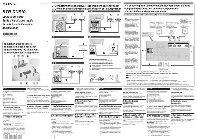
RN 42 RN 44
1-2: 230Vac Power
3-4: 12 to 24V ac/dc power according to switch setting.
5-6: NO Contact, receiver port 1
7-8: NO Contact, receiver port 1
9-10: NO Contact, receiver port 1
11-12: NO Contact, receiver port 1
4.
PROGRAMMING
The Receiver features 3 transmitter programming modes.
•a) By the program key.
•b) Radio supervised authorization (if enabled).
•c) Direct Authorization (if available. Only applies to MUTAN II).
Modes a and b:
1. Mode a. Press the program button. You will hear 2 short beeps. It is now in
programming or learning mode. (Fig. 1).
Mode b. If radio programming is enabled (see section 5.3), you can access programming
mode in the Receiver with a “working” transmitter.
Press the button hidden under the battery cover of a working transmitter, and the
Receiver will enter programming or learning mode, as indicated by 2 short beeps. (Fig.
2).
Fig. 2
Fig. 1

6
2.- Once in programming mode you can authorize the desired transmitters by pressing
any button on each transmitter; for each transmitter programmed a short beep will
sound. (Fig. 3)
3.- To exit programming mode you may do the following: (Fig. 4)
-Wait 30 seconds for the Receiver to leave programming mode on its own.
-Press the program button on the Receiver.
-Press a channel on any of the transmitters that has been authorized other than the last
one programmed.
The Receiver indicates that it has left programming mode with 3 short beeps.
Mode c:
If Direct Authorization programming mode is enabled, pressing any button on a
transmitter near the Receiver will automatically authorize it as long as the Personalization
and Installation Key match. For each transmitter programmed a short beep will sound.
Possible programming issues
If you hear 3 short beeps when trying to program a transmitter, this means the Receiver
has left Programming mode, as the transmitter had already been programmed
previously.
If no beeps sound when trying to program a transmitter, the transmitter’s personalization
or installation key does not match those of the Receiver.
If when trying to program a transmitter 3 double beeps sound, this means the Receiver’s
memory is full and that transmitter has not been programmed.
Fig. 4
Fig. 3

7
5.
USE
Once the transmitters are programmed in the Receiver, pressing a channel will activate
the corresponding Receiver outputs.
WARNING, once working, with the Installation Key, the Memory Card will be linked to the
receiver and can only be reused in a new Receiver through the use of the programmer. See
its instructions.
5.1.
TRANSMITTER REPLACEMENT
With a replacement transmitter previously recorded with a programmer, the user can
automatically authorize the new transmitter by pressing it a couple of times in the vicinity
of the receiver, the old transmitter becoming deauthorized.
5.2.
RECEIVER OUTPUT CONFIGURATION
Be default, the Receivers come configured such that output 1 is activated when it
receives channel 1, and output 2 when it receives channel 2, but there are certain
circumstances in which it is necessary to change this configuration.
We can change the configuration using a compatible Programmer or manually, so let’s
proceed to the next form:
With the receiver connected and working, extract the TM 400 memory card (Fig. 5) and
press the receiver program button (Fig. 6). 3 beeps will sound and the LED
corresponding to output 1 will light up. If you wish to change the channel associated to
this output, press the desired channel on a transmitter in the system (Fig. 7) (the receiver
will emit a beep upon accepting the new channel), if you do not wish to change the
output simply press the receiver program button and go on to output 2 of the receiver,
and so on. After configuring output 4 and pressing the receiver program button (Fig. 8),
it will leave channel programming mode, three long beeps will sound and it will
continue beeping until the TM 400 card is inserted again (Fig. 9). The outputs are now
configured, you can change this configuration at any time.
Fig. 5
Fig. 6

8
Fig. 8
Fig. 8
beeep beeep
beeep
O
R
beep
beeep
Fig. 10
Fig. 7
Fig. 9
5.3.
ENABLE RADIO-SUPERVISED AUTHORIZATION
Standard the receivers only have the button authorization option; if you want to change
the type of authorization to Supervised or Direct, you can use the Programmer or
manually enable the Supervised Authorization mode in the following manner:
With the receiver connected and working, extract the TM 400 memory card (Fig. 5) and
press the receiver program button (Fig. 6). 3 beeps will sound and the LED
corresponding to output 1 will light up (Fig. 6). Now press the program button on a
transmitter already authorized by the receiver; one short beep and one long one will
sound (Fig. 10), indicating that Supervised Authorization mode has been activated. Press
the receiver program button repeatedly until it leaves this mode (Fig. 8) and insert the
TM 400 card again (Fig. 9).
To disable Supervised Authorization mode, proceed in the same manner, in this case
two short and one long beep will sound.

9
5.4.
DELETING TRANSMITTERS
To delete all users from your Receiver, press its program button and hold it down for 10
seconds; you will hear 6 double beeps indicating the memory has been erased.
If you only wish to erase one particular user, you must use a compatible programmer.
5.5.
ANTISPOOFING SYSTEM
When the receiver detects that there are 2 transmitters with the same code functioning in
the system, it puts them on “Reserve” in the memory card and they stop working. For this
transmitter to work again it must be set to “Active”, editing the TM400 card with a
compatible programmer.
To avoid issues, it is recommended this code be left on “Reserve” and the original
transmitter code changed for a new one authorizing it with the receiver.
6.
OPTIONAL ACCESSORIES
•PT Programmers
7.
TECHNICAL CHARACTERISTICS
RECEIVER RN 42
RECEIVER RN 44
POWER SOURCE
230Vac or 12-24V ac/dc
230Vac or 12-24V ac/dc
CONSUMPTION
60mA
60mA
FREQUENCY
433.92Mhz / 868.35Mhz.
433.92Mhz / 868.35Mhz.
No. USERS
400
400
No. OUTPUTS (RELAYS)
2
4
RELAY CONTACTS
1A.
1A.
FUNCTIONAL
TEMPERATURE
-20 to +70ºC
-20 to +70ºC
WATER RESISTANCE
IP 54
IP 54
DIMENSIONS
150x100x60mm.
150x100x60mm.
WEIGHT
454 g
470 g

10
8.
PROGRAMMING QUICK GUIDE
PROGRAMMING SEQUENCE
OR
OUTPUT CONFIGURATION OR ENABLING SUPERVISED
AUTHORIZATION
10
beep
beeep
9
8
beeep beeep
beeep
OR
7
6
bip bip
bip
5
4
3
1
2

11
9.DECLARATION OF CONFORMITY

www.clemsa.es
offices
MADRID NORTE Avda. de la Fuente Nueva, nº 12 nave 8 - 28703 S.S. de los Reyes (Madrid) - Tel. 913 581 110 - Fax 917 293 309 -
BARCELONA Gorcs Lladó, nº 1-9 naves 6-7 - 08210 Barberá del Vallés (Barcelona) - Tel. 935 880 602 - Fax 935 882 854 -
VALENCIA Sequía Calvera, 5-B (P. I. de Sedaví) - 46910 Sedaví (Valencia) - Tel. 963 186 166 - Fax 963 755 683 - [email protected]
SEVILLA La Red Quince, nº 2 (P. I. La Red Sur) - 41500 Alcalá de Guadaira (Sevilla) - Tel. 955 631 006 - Fax 955 630 547 -
MADRID SUR Lluvia, nº 14 (P. I. San José de Valderas) - 28918 Leganés (Madrid) - Tel. 916 428 334 - Fax 916 428 335 -
MÁLAGA José Ortega y Gasset, nº 188 nave 3 - (P. I. Alameda) - 29006 (Málaga) - Tel. 952 023 114 - Fax 952 345 064 -
GALICIA Avda. Alcalde de Lavadores, nº 115 Bajo - 36214 Vigo (Pontevedra) - Tel. 986 493 120 - Fax 986 484 140 - [email protected]
BILBAO Bastegui, nº 7 (P. I. Artunduaga) - 48970 Basauri (Vizcaya) - Tel. 946 757 092 - Fax 944 264 473 - ventas.bilbao@clemsa.es
MURCIA Avda. Francisco Salcillo, Parc. 22/2 (P. I. Oeste) - 30169 San Ginés (Murcia) - Tel. 968 807 732 - Fax 968 825 753 -
CANARIAS Avda. de los Majuelos, nº 42 Edificio Ibis, local 3 - 38107 Santa Cruz de Tenerife - Tel. 922 958 846 - Fax 922 958 731 -
DISTRIBUTORS
DISAUT-LEVANTE, S.L. C/ El Salt, 5 - 03550 San Juan de Alicante (Alicante) - Tel. 965 655 332 - Fax 965 655 933 - direcci[email protected]
DU DETEC, S.L. Echegaray, 37 - 26970 San Pedro de Alcántara (Málaga) - Tel. 952 781 753 - Fax 952 783 786 - [email protected]
AUTOMATISMOS ALJARAFE, S.L. Maestra Lucrecia Alfaro, 6 - 41950 Tomares (Sevilla) - Tel. 954 153 944 - Fax 954 154 179 -
INSTALACIONES ISAMAT, S.L. Avda. Ignacio Wallis, 60 Bj. - 07800 Ibiza (Islas Baleares) - Tel. 971 315 421 - Fax 971 313 862 -
ARC SISTEMES ELECTRICS Antonio Mª Alcover, 43 Bj. - 07013 P. de Mallorca (Islas Baleares) - Tel. 971 256 432 - Fax 971 256 181 -
REDES ALTERNATIVAS, S.L. P. I. San Cristóbal, Parcela 15, Nave 2 - 23710 Bailén (Jaén) - Mobile: 620 140 066 - [email protected]
PULLDOOR, S.L. Ingletera, nº 11 - 28400 Collado Villalba (Madrid) - Tel. 918 505 406 - Fax 918 506 173
© 2013 CLEMSA_ Total or partial reproduction is prohibited, even when citing the source. All copying and imitation will be prosecuted according to law.
We reserve the right to effect changes to introduce improvements without prior notice. 06_2017 921110558477
This manual suits for next models
2
Table of contents


