Unit 1, 10 Duerdin St, Clayton VIC 3168, Australia
Tel: +61 3 9239 8088 Fax: +61 3 9239 8024
E-mail: tech@clenergy.com.au www.clenergy.com.au
01page of 05
Introduction
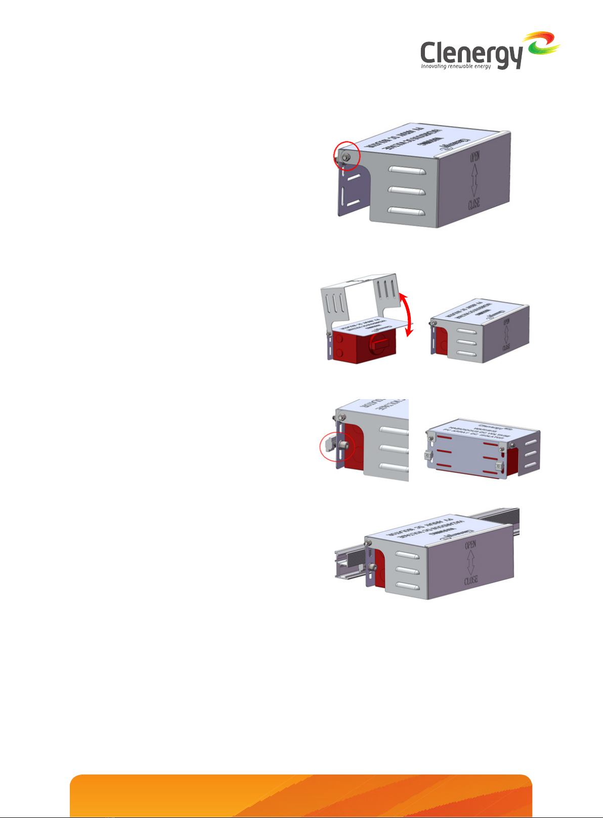
1. Introduction
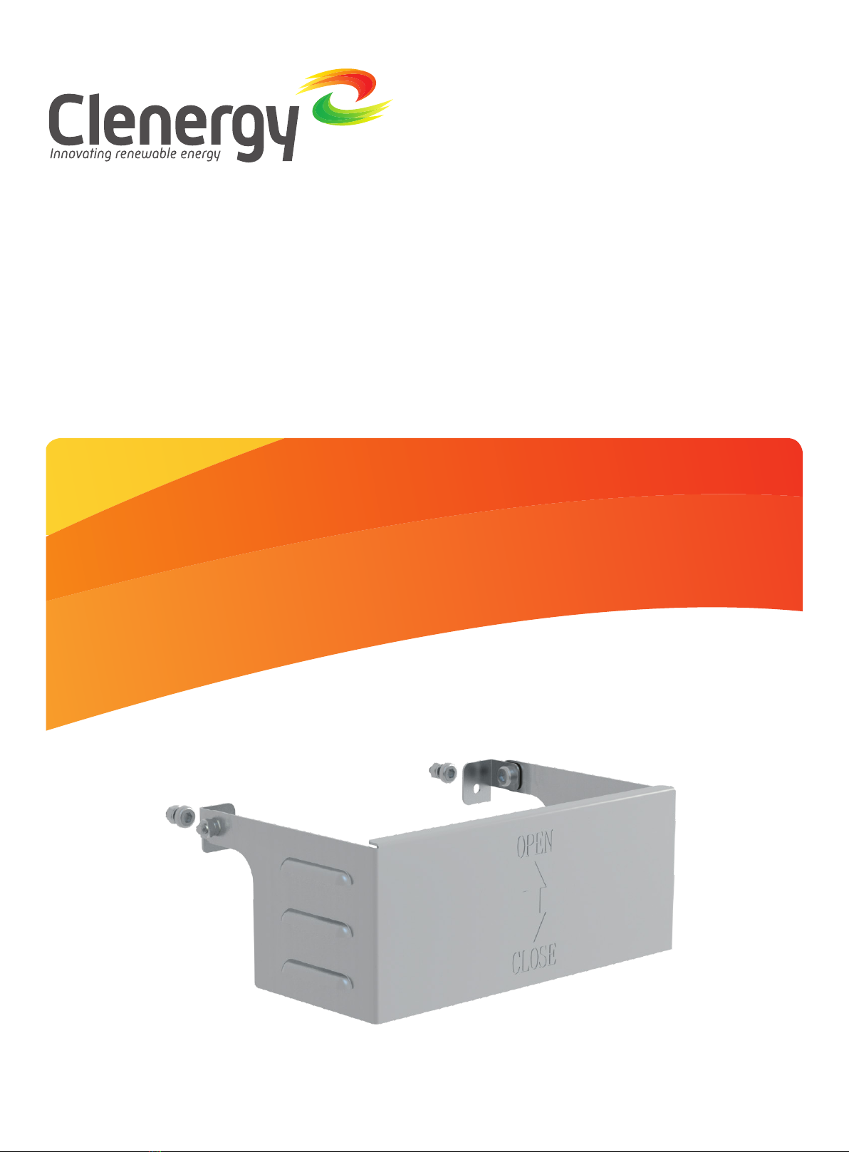
PV-ezRack Cover for Isolator Bracket II is
specially designed for Isolator Bracket II,
suitable for PV array AC/DC isolators.
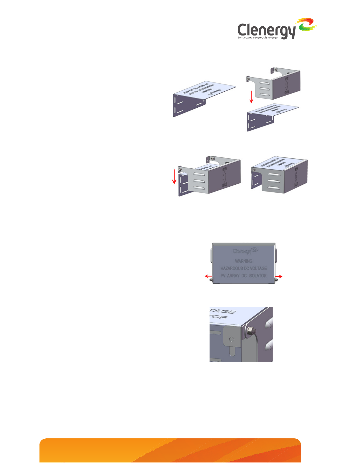
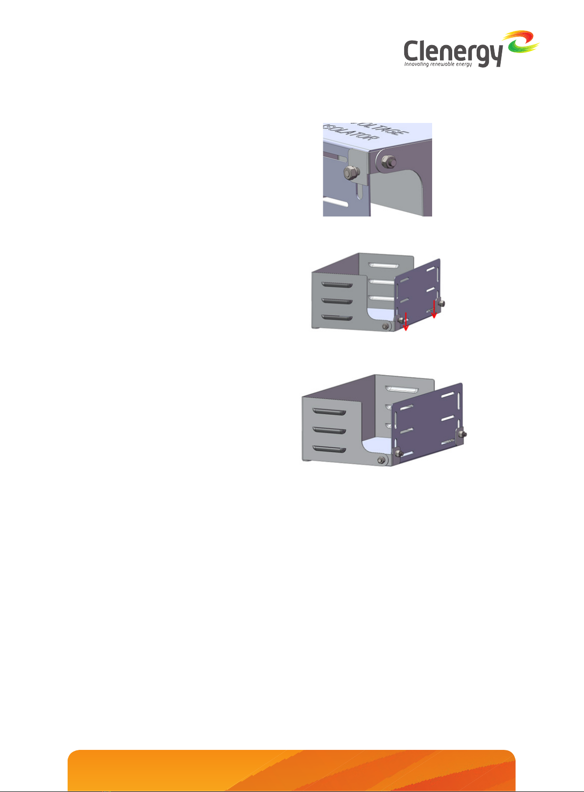
When correctly installed, the Isolator cover
assembly with isolator bracket II is designed
to function as a shroud to protect isolator and
its enclosure from direct exposure to sunlight
and rain as required by clause 4.3.3.3.2 of AS/
NZS 5033:2014 Amdt 2: 2018. The isolator
must have a suitable enclosure conforming to
clause 4.3.3.3.1 of AS/NZS 5033:2014 Amdt 2:
2018. The isolator and its enclosure fit inside
the shroud after assembly of isolator bracket II
and the cover.
Please review this guide thoroughly before
installing PV-ezRack Cover for Isolator Bracket
II.
The installer is solely responsible for:
• Complying with all applicable local or national
building codes, including any that may
supersede this manual;
• Ensuring that PV-ezRack and other products
are appropriate for the particular installation and
the installation environment;
• Using only PV-ezRack parts and installer-
supplied parts as specified by the PV-ezRack
project plan. (substitution of parts may void the
warranty and invalidate the letter of certification);
• Recycle according to the local relevant statutes;
• Removal by reversing the installation process;
• Ensure that there are no less than two
professionals working on panel installation;
• Ensure the installation of related electrical
equipment is performed by licenced
electricians;
• Ensuring safe installation of all electrical
aspects of the PV array. This includes adequate
earth bonding of the PV array and PV-ezRack®
components as required in AS/NZS 5033-2014
AMDT 2 2-2018.
Introduction
Tools &Component list
Installation Instruction
01
02
03
List of Contents