Cleveland Controls A-08740 0 Series User manual

• OPACITY MONITOR MANUAL IM-A-08740-05 • 1
Series A-08740-*0
Universal Opacity Monitorwith LED Light Source
Instruction Manual A-08740.05

2 • OPACITY MONITOR MANUAL IM-A-08740-05 •
Revision Control
Documentation Number and Revision Log
This manual is UniControl Inc. document number IM-A-08740-05 dated February 1, 2022.
Manual Revision Date
IM-A-08740-05 12/27/2021
IM-A-08740-04 11/01/2011
Hardware Revision Number
Electronics Unit LED light source
P/N 31180 Light Source Assembly LED light source
P/N 31181 Receiver Assembly LED light source
P/N 27367 Sight Glass Assembly (qty. of 2)
P/N 31726 Purge Air Blower Kit
Current Software Version Release Date
1.23 05/10/2004
Symbols Used in This Manual
The following symbols may be used in this manual to denote certain conditions.
Danger symbol indicates an immanently hazardous situation, which, if
not avoided, will result in death or serious injury.
Warning symbol indicates a potentially hazardous situation, which, if not
avoided, could result in death or serious injury.
Caution symbol indicates a potentially hazardous situation, which, if not
avoided, could result in minor or moderate injury.
Caution used without the safety alert symbol indicates a potentially
hazardous situation, which, if not avoided, may result in property damage.
Photo 1 (Front Cover): Electronics/Display Assembly

• OPACITY MONITOR MANUAL IM-A-08740-05 • 3
Safety Warnings
Failure to comply in full with the following safety requirements can result in equipment damage and personal
injury/death.
1. Read the entire manual to become familiar with the use and operation of this device.
2. Only qualied personnel should attempt to install, wire, commission, startup, service or operate this
device.
3. This device is not suitable for use in an explosive ambient atmosphere.
4. Before working on this device, be sure that you understand the processes affected by this device
completely.
5. Before working on this device, be sure that any process affected by this device is secure and safe for
servicing.
6. Take appropriate precautions to avoid electric shock when working with this device near water.
7. Exercise caution while wiring or working on this device. Multiple voltage sources may be present: take
appropriate precautions to avoid electric shock.
8. RFI (radio frequency interference) can affect adversely the operation of this device and devices that are
connected together as a system. Do not use radios near this equipment: examples include, but are not
limited to; citizen band radios (CB), walkie-talkies, transceivers, and amateur radios (HAM).
Wiring Tips
1. Wire with extreme caution!
2. All wiring must conform to the National Electrical Code and to local code regulations. Verify all electrical
ratings on equipment.
3. Connecting high voltage to the low voltage circuits will damage the circuitry!
4. Mount the unit in such a manner that the wiring cable from the main electronics does not touch or
approach any high magnetic source. If mounted near a high magnetic source (such as motor starters, 3
ohm transformers, ignitors, etc.), electronic interference may cause the display to read incorrectly.
Storage, Handling & Unpacking
The following components may be shipped individually. Specic purchase orders may include some or all of the
following items.
Electronics Unit
P/N 31180 Light Source Assembly
P/N 31181 Receiver Assembly
P/N 27367 Sight Glass Assembly (qty. of 2)
P/N 31726 Purge Air Blower Kit including (2) 6-ft. lengths of flex conduit, the blower, an air inlet lter, & (4)
ttings
P/N 20458 Series L-05500 Audible/Visual Alarm
Documentation: Instruction Manual A-08740.05

4 • OPACITY MONITOR MANUAL IM-A-08740-05 •

• OPACITY MONITOR MANUAL IM-A-08740-05 • 5
Table of Contents
Revision Control ................................................................................................................................................................... 2
Symbols Used in This Manual.............................................................................................................................................. 2
Safety Warnings.................................................................................................................................................................... 3
Wiring Tips ............................................................................................................................................................................ 3
Storage, Handling & Unpacking .......................................................................................................................................... 3
1.0 Introduction 7
1.1 Description of Operation................................................................................................................................................ 7
1.2 Specications ................................................................................................................................................................ 8
1.3 Nomenclature.................................................................................................................................................................. 9
2.0 Installation 10
2.1 Mounting ....................................................................................................................................................................... 10
2.2 Wiring ............................................................................................................................................................................ 11
3.0 Operation & Maintenance 12
3.1 Displays and Indicators................................................................................................................................................ 12
3.2 Field Conguration on Continuous Display Screen................................................................................................... 12
3.3 Calibration on Continuous Display Screen................................................................................................................. 13
3.4 Other Adjustments on Continuous Display Screen ................................................................................................... 13
4.0 Miscellaneous 14
4.1 Retransmission of Process Variable ........................................................................................................................... 14
4.2 Modbus Communications ............................................................................................................................................ 14
4.3 Troubleshooting (Diagnostic LED’s) ............................................................................................................................ 14
5.0 Customer Service Information 15
5.1 Contacts ........................................................................................................................................................................ 15
5.2 Repairs .......................................................................................................................................................................... 15
5.3 Service .......................................................................................................................................................................... 15
5.4 Standard Terms and Conditions of Sale...................................................................................................................... 16
6. Appendices: Drawings & Tables 17
Photo 1 (Front Cover): Electronics/Display Assembly ....................................................................................................... 2
Photo 2: Optional Separate Purchase: P/N 31726 Purge Air Blower Kit........................................................................... 7
Photo 3: Stack Units, left to right: P/N 31180 Light Source and P/N 31181 Receiver .................................................... 10
Figure 1: Printed Circuit Board Assembly for A-08740 Universal Opacity Monitor. ..................................................... 18
Figure 2: Housing Dimensions for A-08740 Universal Opacity Monitor......................................................................... 19
Figure 3: Mounting the Breeching Units (A-08740 Universal Opacity Monitor). ........................................................... 20
Figure 4: Typical Air Supply Arrangement for Sight Glass Purge................................................................................... 21
Figure 5: Typical Air Supply Arrangement for Sight Glass Purge with Blower (P/N 31726). ........................................ 22
Figure 6: Field Wiring for Universal Opacity Monitor, basic model (no auxiliary modules).......................................... 23
Figure 7: Field Wiring for Universal Opacity Monitor Equipped with NYC Burner Cutoff Module. .............................. 24
Figure 8: Field Wiring for Universal Opacity Monitor Equipped with Overre Air Timer Module. ............................... 25
Figure 9: Field Wiring for Universal Opacity Monitor Equipped with Purge Air Blower System.................................. 26
Figure 10: Summary of Continuous Display Screen ........................................................................................................ 27
Figure 11a: Scrolling Display Screens for Standard Models A-08740-A0-0X (1a through 5) ....................................... 28
Figure 11b: Scrolling Display Screens for Standard Models A-08740-A0-0X (6 through 10d)..................................... 29
Figure 11c: Scrolling Display Screens for Standard Models A-08740-A0-0X (11a through 13) ................................... 30
Figure 12a: Scrolling Display Screens for Standard Models A-08740-A0-1X (1a through 5) ....................................... 31
Figure 12b: Scrolling Display Screens for Standard Models A-08740-A0-1X (6 through 10d)..................................... 32
Figure 12c: Scrolling Display Screens for Standard Models A-08740-A0-1X (11a through 13) ................................... 33
Figure 13a: Scrolling Display Screens for Standard Models A-08740-A0-2X (1a through 5) ....................................... 34
Figure 13b: Scrolling Display Screens for Standard Models A-08740-A0-2X (6 through 10d)..................................... 35
Figure 13c: Scrolling Display Screens for Standard Models A-08740-A0-2X (11a through 13) ................................... 36
Figure 14: Modbus Memory Addresses ........................................................................................................................... 37
Figure 15: “Processor Running” LED ............................................................................................................................... 37
Figure 16: Troubleshooting................................................................................................................................................ 38

6 • OPACITY MONITOR MANUAL IM-A-08740-05 •

• OPACITY MONITOR MANUAL IM-A-08740-05 • 7
1.0 INTRODUCTION
1.1 Description of Operation
The Cleveland Controls Model A-08740 Universal Opacity Monitor provides reliable, continuous measurement
of the density of conned particulates such as dust or smoke. It is easy to calibrate and requires no routine
maintenance other than occasionally cleaning the sight glass.
The basic system consists of an electronics unit and two breeching components, consisting of an LED
light source that directs a beam through the measured particulate, and a light sensor that receives the beam,
detects changes in opacity, and sends a proportional signal to the electronics unit. The wide-beam light source
and narrow-view receiver make installation easy because alignment of the breeching units does not need to be
precise.The electronics produces a digital readout of percent opacity and a 4-20 mA DC output signal suitable
for recording, display, or indication. SPDT contacts are provided for a remote alarm (which can be purchased
separately: Cleveland Controls L-05500-00). The operator can select manual or automatic alarm reset. Modbus
communications for interface with a SCADA system (Supervisory Control and Data Acquisition system) or other
controls is standard. A standard serial printer port is provided. The electronics unit is available in open-mount,
surface-mount, and flush-mount formats. It can be installed in any dry, convenient area within 250 feet of the
light source and receiver units. The standard model has a vacuum fluorescent display with three status LED’s.
There are four LED indicators on units equipped with auxiliary functions (described below).
The Burner Cutoff Auxiliary Function is a delayed-off timer that shuts the burner down if an alarm
condition (opacity exceeding 20%) persists for 120 seconds. The timer can be reset manually only after
reduction of opacity: it cannot be reset when opacity is above 20%. (This feature meets the requirements of
the New York City air pollution control code for alarm and burner control functions). Model A-08740 Opacity
Monitors equipped with the burner cutoff function have four LED indicators on the front of the electronics panel,
marked Clear, Smoke, Alarm, and Burner Off. In addition, an audible alarm with adjustable trip point and delay is
mounted on the front face of the electronics unit.
The Overre Air Timer Auxiliary Function is a delayed-off timer that provides relay contacts for the control
of smoke-reduction air in coal-red installations. As soon as opacity exceeds the alarm trip point, the relay is
energized. It remains energized as long as the alarm condition persists. After the alarm condition is corrected,
the relay remains energized for an adjustable period up to ve minutes. Model A-08740 Opacity Monitors
equipped with the overre air timer function have four LED indicators on the front of the electronics panel,
marked Clear, Smoke, Alarm, and Overre Air.
Please Note:
• The Cleveland Controls Model A-08740 Universal Opacity Monitor as shipped includes the electronics
unit, light source, receiver, and two sight glass assemblies that must be mounted in the duct.
• The traverse and mounting pipe, plus any required purge connections and/or air supplies, are to be
provided by the installing contractor.
P/N 31726 Purge Air Blower Kit for positive pressure flue gas pressure:
Purge air is recommended if the flue duct is held at positive pressure.
Sight glass lenses on the ends of the traverse pipe will become cloudy
when the flue gas pressure is greater than the ambient air pressure,
because water from the flue gas condenses on the lenses. This results
in false opacity alarms. The lenses can be purged with instrument air (not
plant air) if sufcient volume is available, but usually it is not. The solu-
tion is a blower to provide ambient air at low pressure (not compressed)
that will not condense water on the lenses. A single blower, wired to run
whenever the burner is running, can be connected to ttings near the
lenses. Cleveland Controls P/N 31726 Purge Air Blower Kit operates
with 120/230 V ac, and includes a blower with air inlet lter, four ttings,
and two 6-ft lengths of 1-inch liquid-tight flexible conduit used for tubing
connections to the traverse pipe near both the light source and receiver
lens.

8 • OPACITY MONITOR MANUAL IM-A-08740-05 •
1.2 Specications
Power requirements:120 V ac ± 10%, 50/60 Hz.
Ambient temperature ranges: 32–130 ºF (0-54 ºC) for electronics unit. 32–160 ºF (0-70 ºC) for light source and
receiver units.
Fuse: One, @ 1 Amp.
Measurement range: 0 to 100% opacity.
Retransmit Output range: 4-20 mA dc, 750 Ohms maximum load. Directly proportional to measurement range,
where 4 mA = 0% and 20 mA = 100%. Output is grounded (not isolated.)
Resolution: Digital meter reads 0-100% opacity with 1% resolution.
Response time: 1 second for 90% of actual change in opacity.
Accuracy: ± 5% opacity under all specied operating conditions.
LED light source to receiver distance: minimum 4 ft. (1.20 m.), to maximum 15 ft. (4.57 m.).
LED light source lamp life: 1 year minimum.
Spectral response of photocell: 350–1100 nM.
Cable length: 250 ft. (76 m.) maximum.
Indicators:
Green: “Clear” LED.
Yellow: “Smoke” LED and flashing display.
Red: “Alarm” LED and flashing display.
Alarm timer: adjustable 0-300 second delay.
Alarm trip point: adjustable 0-99% opacity.
Alarm reset: automatic; eld-convertible to manual.
Alarm contacts: isolated SPDT, 10 Amp, 120 V ac resistive, fail safe.
Purge Delay timer: adjustable 1-600 second delay.
NYC Burner Cutoff (optional): xed 20% trip point and xed 2-minute (120-second) delay.
NYC Burner Cutoff contacts: isolated SPDT, 10 Amp, 120 V ac resistive, fail safe.
Overre air timer (optional): maintains contact closure after smoke abatement for a period adjustable
from 1-300 seconds.
Overre air contacts: isolated SPDT, 10 amp, 120 V ac resistive, fail safe.
Housing for enclosed models: NEMA 1.
Relative Humidity: 0-90%, non-condensing.
Modbus Communication: RTU. 9600 or 19200 Baud rate. N/8/1 (no parity, 8 data bits, 1 stop bit).
Printer port: RS232 serial port, DB9-M connector, 9600 baud, N81 (no parity, 8 data bits, 1 stop bit).
Output adjustable, generated every 0-60 minutes, where 0 = disabled.
Output format: 5 sequence #, blank space, 3 digit opacity, “%” symbol, carriage return, line feed.
Example: 01234 011% c/r l/f
Shipping Weight: varies with options; these are typical:
Electronics units in enclosures are 7.5-8.5 lbs.
Open-mounted electronics units are 6.5-8.0 lbs.
Light source and receiver, combined, 9 lbs.
Approvals: NYC DEP. UL & CUL pending.
SPECIFICATIONS ARE SUBJECT TO CHANGE.

• OPACITY MONITOR MANUAL IM-A-08740-05 • 9
1.3 Nomenclature
The basic catalog number for the Cleveland Controls Model A-08740 Universal Opacity Monitor is shown
below. Replace sufxes A and B with selections from the table below.
The standard base unit includes one electronics unit, one pair of LED light source and receiver units, and two
sight glass assemblies. The electronics unit will include any auxiliary module that was purchased (NYC burner
cutoff timer or overre air timer for stokers). All electronics units have a vacuum fluorescent display with 3 LED’s
(standard: Clear, Smoke, and Alarm) or 4 LED’s (if an auxiliary function is present). Other standard features
include: adjustable alarm trip point and delay, eld-selectable auto/manual alarm reset, retransmitted 4-20 mA dc
output, Modbus communication, a serial printer port, and a contact closure for a remote alarm. Please note that
the printer and remote alarm are not included and must be supplied by the customer. However, the Cleveland
Controls P/N 20458 Series L-05500-00 Audible/Visual Alarm can be purchased separately. Also available
separately, the Cleveland Controls P/N 31726 Purge Air Blower Kit is used in positive flue gas pressure
applications.
The Model A-08740 Universal Opacity Monitor is the direct replacement for the obsolete Model A-08711
Opacity Monitor.
A - 0 8 7 4 0 - *A 0 - A - B
*A = Current Model Designation
-A-: Auxiliary Modules for Specic Applications
A = 0. None.
A = 1. Burner Cutoff Timer with audible alarm & “Burner Status” LED on panel face. NYC DEP
approved.
A = 2. Overre Air Timer with “Overre Air” LED for stoker applications.
-B-: Mounting/Enclosure Options
B = 0. Open-mount package for OEM applications.
B = 1. Cabinet: surface-mount on wall (NEMA 1).
B = 2. Cabinet: semi-flush mount on panel (NEMA 1).

10 • OPACITY MONITOR MANUAL IM-A-08740-05 •
Wiring Tips
• Wire with extreme caution!
• All wiring must conform to the National Electrical Code and to local code regulations. Verify all electrical ratings
on equipment.
• Connecting high voltage to the low voltage circuits will damage the circuitry!
• Mount the display unit in such a manner that the wiring cable from the main electronics does not touch or ap-
proach any high magnetic source. If mounted near a high magnetic source, electronic interference may cause
the display to read incorrectly.
2.0 INSTALLATION
2.1 Mounting
Mount the electronics/display unit in a dry location where the ambient temperature is within the specied
temperature range, 32-160 ºF (0-70 ºC).
• Mount the unit away from excessive vibration.
• Do not mount in a wiring cabinet that has any power wiring in excess of 120 V ac.
• Mount the unit in such a manner that the wiring cable from the main electronics does not touch or approach
any high magnetic source. If mounted near a high magnetic source, electronic interference may cause the display
to read incorrectly.
Referring to Figure 3, mount the LED light source and receiver units directly opposite each other on the
particulate passage. Select a position where a true, low-turbulence particulate sample is present, and where the
sight glasses are safely and conveniently accessible for cleaning. For applications where soot on the sight glass
might present a problem, apply purge air as shown in Figure 4 and Figure 5.
The width of the passage must not exceed 15 feet (4.57 meters). The length of the wires to the control unit
must not exceed 250 feet (76 meters).
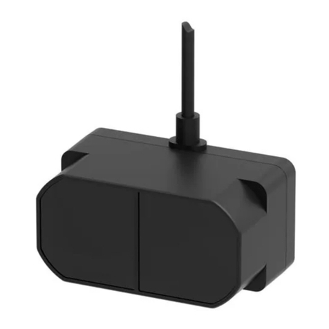
Stack Units, left to right: P/N 31180 Light Source and P/N 31181 Receiver: These stack-mounted units are included with the base
electronics/display unit and two P/N 27367 Sight Glass Assemblies.

• OPACITY MONITOR MANUAL IM-A-08740-05 • 11
2.2 Wiring
The following information on wiring is generally applicable to all models. Refer also to the wiring diagrams
in this manual (Figure 6 - Figure 9). Field wiring consists of 120 V ac control wiring, dc signal wiring, and
Modbus wiring.
120 V ac Control wiring connecting the opacity monitor to the power source must be 14 AWG minimum, and
must not be run in conduit with low voltage signal wiring. Signal wiring (dc) and Modbus wiring may be run in the
same conduit if practical.
Dc wiring is at voltage levels of 24 V dc or less. Unless otherwise specied, all signals are 4-20 mA dc. Each
signal requires a shielded 2-wire pair, 16 AWG minimum.
To wire the LED light source and receiver, loosen the three (3) screws on the back cover and remove it,
giving access to the eld wiring terminals. Refer to Figures 5-7 and wire the units exactly as shown. The wires may
be no longer than 250 feet (76 meters).
While no damage results if the wires are connected to the wrong unit, or if the polarity of any of the wires
is reversed, the unit will not function. Connecting 120 V ac to the LED light source or receiver may result in
serious damage. If the light source does not come on when 120 V ac is applied, remove the power immediately
and recheck the eld wiring.
The voltage on the LED light source wires is approximately 4–10 V dc. If these wires are shorted to each other,
the light source power supply will shut down. Shielded wire must be used on the receiver, and the shield must not
be shorted to ground. A grounded shield may result in erratic operation or a shorted 4-20 mA output.
RS-485 Modbus wiring: a plus terminal is provided for the plus signal, a minus terminal for the minus signal,
and a shield (shd) for shield wire. Generally, Belden 9841™ shielded cable or equivalent is suggested for RS-485
communications.

12 • OPACITY MONITOR MANUAL IM-A-08740-05 •
3.0 Operation & Maintenance
3.1 Displays and Indicators
3.1.1 Continuous Display Screen
When power is applied to the unit, the continuous display screen lights. It provides a continuous display of
particulate density from 000% Opacity (no particulates detected) to 100% Opacity (particulates are dense enough
to block all light), in 1% increments. The display window indicates the parameters and messages shown in Figures
10-13 in this manual.
3.1.2 Indicator LED Lights and Status Messages
The green LED lights and the “Clear” message appears on the rst line of the display to indicate that opacity
is below alarm trip point. As soon as the trip point is exceeded, the green LED and “Clear” message go out and
the yellow LED and blinking “Smoke” message come on. On the second line of the display, the alarm delay timer
countdown appears. The red LED and blinking “Alarm” display are activated if the excessive opacity persists
after the alarm delay period expires. If automatic alarm reset mode is selected, the Clear message and green LED
will resume after the smoke has cleared to the point that the monitor detects an opacity percentage less than the
alarm trip point. If manual alarm reset mode is selected, press the reset button to reset the alarm in all Standard
and Overre Air Timer models. See Figures 10 and 13.
For NYC models equipped with the 2-minute shutdown and alarm options, reset both the main and NYC
alarms by rst pressing the reset button, and then pressing the “Dec” key to reset the NYC alarm, and the “Inc”
key to reset the main alarm. If the main alarm is in automatic reset mode, it will be necessary to reset only the NYC
alarm. See Figure 11.
3.1.3 Output Functions
A 4-20 mA signal corresponding to 0 to 100% opacity provides for remote recording, control, or indication.
SPDT alarm contacts are provided for remote alarm or control. The alarm relay is normally energized for fail safe
operation. Refer to lines 11a through 11c on Figures 11, 12, and 13 for calibration of the retransmitted output.
Note that the output can be varied from the low (4 mA dc) and high (20 mA dc) values by ±0.5 mA dc.
3.2 Field Conguration on Continuous Display Screen
The scrolling display permits the operator to view and change parameters. Press the “Enter” button repeatedly
to scroll through the parameters, which appear on the bottom line of the display. With a parameter visible, press
the “Inc” button to increase its value. Press the “Dec” button to decrease its value. The new value becomes
effective immediately: pressing “Enter” again brings up the next parameter.
After 10 seconds of inactivity, the display reverts to the default screen except during calibration mode.
Following an alarm event, press the “Reset” button to clear the “Alarm” message and restore the “Clear”
message to the display if the unit is a Standard or Overre Air Timer model congured (on the printed circuit
board) for manual alarm reset. If the unit is congured for automatic alarm reset, the “Clear” message will replace
the “Alarm” message automatically as soon as the excessive opacity is cleared.
For NYC models equipped with the 2-minute shutdown and alarm options, reset both the main and NYC
alarms by rst pressing the reset button, and then pressing the “Dec” key to reset the NYC alarm, and the “Inc”
key to reset the main alarm. If the main alarm is in automatic reset mode, it will still be necessary to reset the NYC
alarm.
The scrolling display includes the parameters and messages shown on Figures 10 through 13.

• OPACITY MONITOR MANUAL IM-A-08740-05 • 13
3.3 Calibration on Continuous Display Screen
For a summary of the calibration information below, refer to Figures 10 through 13.
3.3.1 AUTO CALIBRATION MODE
To calibrate the LED light source and receiver units, press the “Enter” button until the “Enter Cal Menu?”
message appears. While holding down the “Inc” button, press the “Dec” button simultaneously to display the
“Calibrate Opacity” screen. While holding down the “Inc” button, press the “Dec” button simultaneously to display
the “Auto-Cal Purge” screen and initiate the purge countdown from the purge delay value (which is already
congured: see section 3.2 above, and line 5 in Figures 11, 12, or 13). Following the countdown, the “Calibrate
Phase-1” message appears, along with a countdown from 04 to 00, and the LED light source lamp goes out.
Following the countdown, the “Calibrate Phase-2” message appears and the LED light source lamp comes on and
varies in intensity as it adjusts to the diameter of the stack. While the adjustment is in progress, a countdown from
“40” displays on the screen, but calibration may be complete before it reaches “00”. At the end of the calibration
process, either the default screen display or a calibration error screen appears. “Cal Err #1” means that the
receiver has not detected enough light from the LED light source. “Cal Err #2” means that the receiver has
detected too much light from the LED light source. In either case, the process conditions responsible for the error
message must be corrected, and then the calibration process must be repeated until successful.
To calibrate the retransmitted 4-20 mA dc signal, connect a 4-20 mA meter to the retransmit terminals,
and then follow the steps above until the “Calibrate Opacity” screen appears. Next, press “Enter” to display the
“Calibrate Retrans” message. While holding down the “Inc” button, press the “Dec” button simultaneously to
display the “Set Retrans Low” screen. Observing the meter reading, use the “Inc” and “Dec” keys to correct the
value. The output can be varied from 4 mA by ± 0.5 mA dc. When satised, press the “Enter” key again and the
“Set Retrans High” message appears. Observing the meter reading, use the “Inc” and “Dec” keys to correct the
value. The output can be varied from 20 mA by ± 0.5 mA dc.
3.3.2 MANUAL CALIBRATION MODE
To calibrate the LED light source and receiver units, press the “Enter” button until the “Enter Cal Menu?”
message appears. While holding down the “Inc” button, press the “Dec” button simultaneously to display the
“Stack Clear?” screen. Check the stack, and press “Enter” to conrm that it is clear. The “Calibrate Phase-1”
message is displayed, along with a countdown from 04 to 00, and the LED light source lamp goes out. Following
the countdown, the “Calibrate Phase-2” message appears and the LED light source lamp comes on and varies
in intensity as it adjusts to the diameter of the stack. While the adjustment is in progress, a countdown from “40”
displays on the screen, but calibration may be complete before it reaches “00”. At the end of the calibration
process, either the default screen display or a calibration error screen appears. “Cal Err #1” means that the
receiver has not detected enough light from the LED light source. “Cal Err #2” means that the receiver has
detected too much light from the LED light source. In either case, the process conditions responsible for the error
message must be corrected, and then the calibration process must be repeated until successful.
To calibrate the retransmitted 4-20 mA DC signal, connect a 4-20 mA meter to the retransmit terminals,
and then follow the steps above until the “Calibrate Opacity” screen appears. Next, press “Enter” to display the
“Calibrate Retrans” message. While holding down the “Inc” button, press the “Dec” button simultaneously to
display the “Set Retrans Low” screen. Observing the meter reading, use the “Inc” and “Dec” keys to correct the
value. The output can be varied from 4 mA by ±0.5 mA dc. When satised, press the “Enter” key again and the
“Set Retrans High” message is displayed. Observing the meter reading, use the “Inc” and “Dec” keys to correct
the value. The output can be varied from 20 mA by ± 0.5 mA dc.
3.4 Other Adjustments on Continuous Display Screen
MODBUS ADDR:Set the Modbus address from 001– 247, using the “Inc” key to increase the value or
the “Dec” key to decrease the value.
BAUD RATE: Select a baud rate of 9600 or 19200, using the “Inc” or the “Dec” key to toggle between
these values.
PRINT INTERVAL: Select a print interval value between 0 and 60 minutes to regulate printed report fre-
quency. A print interval of “0” disables the printer output.

14 • OPACITY MONITOR MANUAL IM-A-08740-05 •
4.0 Miscellaneous
4.1 Retransmission of Process Variable
Refer to the overall wiring diagrams (Figures 6-9). The terminals for the retransmission of the process variable
are located on the printed circuit board. They are marked “4-20 ma.”
4.2 Modbus Communications
Refer to the overall wiring diagrams (Figures 6-9). Terminals for Modbus communication are located on the
lower left of the printed circuit board. They are marked “RS-485 +, -, SHD.” These terminals provide information
with Modbus protocol using RS-485.
The Modbus address assignments are shown in Figure 14.
4.3 Troubleshooting (Diagnostic LED’s)
4.31 Diagnostic LED’s
LED’s are provided for onboard diagnostic of the I/O (Input/Output). The Relay Status and “Processor
Running” LED’s are identied in Figure 1.
The “Processor Running” LED indicates the state of the microprocessor by blinking at different rates as
shown in Figure 15.
4.32 Checksum Error
When the microprocessor values do not match the values stored in memory, “Checksum Error” is displayed.
All logic functions stop. To correct the Checksum Error, turn the power off and then back on. If this procedure
doesn’t rectify the error, reenter all control parameters. If the problem persists, contact the sales ofce where you
purchased the unit.

• OPACITY MONITOR MANUAL IM-A-08740-05 • 15
5.0 CUSTOMER SERVICE INFORMATION
5.1 Contact Us
http://www.clevelandcontrols.com
Cleveland Controls
1111 Brookpark Road
Cleveland OH 44109
Cleveland Controls Sales & Customer Service Ofce
Telephone: (216) 398-4414
Fax: (216) 398-8558
e-mail: [email protected]
e-mail: customerservice@unicontrolinc.com
5.2 Repairs
Damaged or defective units can be returned to the factory for repair. However, factory authorization must be obtained
before shipping whether warranty or non-warranty service is required, and all units
must be shipped prepaid. A letter of transmittal that includes the following information
should accompany the returned unit:
1. Name and telephone number of contact person for any questions about the unit.
2. Indicate whether warranty or non-warranty service is requested.
3. Attach purchase order for all out-of-warranty repairs.
4. Indicate original purchase order number and date of purchase.
5. Location, type of service, and length of time in service of the unit.
6. Description of the faulty operation of the device and circumstances of the failure.
7. Complete shipping instructions for the return of the repaired instrument.
8. Return Goods Authorization number provided by the factory when you called.
Clearly label the shipping container:
RETURN FOR REPAIR
Model _____________
RG # ______________
Ship prepaid to the Cleveland Controls Customer Service Dept.
(address above in Paragraph 5.1)
5.3 Service
A Maintenance and Service Contract can ensure trouble-free, economical operation of Cleveland Controls equipment
for many years. One-time on site service by a factory-trained service engineer can also be provided as needed. Contact
Cleveland Controls for information on these service options.
Please follow this procedure. It
expedites handling of the returned
item, and avoids unnecessary
additional charges for inspection and
testing to determine the problem
before repairing it.

16 • OPACITY MONITOR MANUAL IM-A-08740-05 •
5.4 Standard Terms and Conditions of Sale
TERMS OF SALE: 1% discount if paid in ten (10) days, net amount due and payable in thirty (30) days.
AGREEMENT OF SALE: Acceptance by Seller of any order placed for goods whether submitted on Buyer’s purchase order form or on seller’s
Sales Order Acknowledgment form, shall be subject to Seller’s Standard Terms and Conditions of Sale and is conditioned upon the Buyer’s
acceptance of these Standard Terms and Conditions.
TERMS OF CONTRACT: Any terms or conditions of the buyer’s order which are inconsistent with these terms and conditions shall not be
binding on the Seller and shall not be considered applicable to the sale or shipment of goods or materials. Unless buyer shall notify Seller in
writing to the contrary within ten (10) days after the mailing of the Sales Contract by Seller, acceptance of the terms and conditions hereof by
Buyer shall be indicated and, in the absence of such notication, the sale and shipment by Seller of the goods and materials covered hereby shall
be conclusively deemed to be subject to the terms and conditions hereof.
PRICES: All prices and specications and applicable discounts are subject to change without notice. Sales contracts which call for delivery in
the future will be billed at prices in effect at the time of shipment. Shipping weights shown are approximate and subject to change without notice.
SHIPMENT AND PAYMENTS: All prices contained on the Sales Contract are FOB factory in Cleveland, Ohio. No freight is allowed on any
shipments. Shipments and deliveries shall at all times be subject to the approval of Seller’s Credit Department, and at any time seller may require
payment in advance or satisfactory security or guarantee that invoices will be promptly paid when due. If buyer fails to comply with any terms
of payment, seller, in addition to its other rights and remedies, but not in limitation thereof, reserves the right to withhold further deliveries or
terminate the Agreement, and any unpaid amount thereon shall become due immediately. Terms of payment shall be as set forth on the Sales
Contract.
DELAYS AND DEFAULTS: Delays or defaults in delivery by Seller of the goods and materials covered by the Sales Contract shall be excused
so far as the same is caused by re, strikes, accident, governmental regulation, or any delays unavoidable or beyond reasonable control of Seller.
In no event shall Seller be liable for any consequential, special, or contingent damages on account of any default or delay in delivery.
NON-CANCELLATION: Orders are not subject to suspension, reduction, or cancellation, except on terms that will indemnify Seller against
loss.
SPECIFICATIONS: Seller relies on specications and other data furnished by the Buyer, an architect, contractor, or consulting engineer in all
phases of the work covered by the Sales Contract. Seller shall be responsible to check quantities only. Alterations to or changes in specications,
approval of samples, changes in delivery instructions and all other instructions must be submitted in writing to Seller.
In the event Seller performs design or engineering work at the request of Buyer, an architect, contractor, consulting engineer, or representative
in any phase of the work covered by the Sales Contract, Seller shall not be responsible for any damages claimed by Buyer as a result of alleged
errors or defects in such design or engineering work.
WARRANTY AND LIMITATION OF LIABILITY: Seller warrants that the goods supplied by it have been manufactured in accordance with its
standard manufacturing practices and conform to the contract or catalog description set forth in the order. Seller further warrants that the goods
supplied by it are t for the ordinary purpose or purposes specied in its catalog for which such goods are used when installed in accordance with
Seller’s recommended installation procedures. Except as stated herein, Seller makes no express warranty with respect to goods supplied by it
and Seller makes no warranty that the goods are t for any particular purpose.
When the use of materials not manufactured by Seller is suggested by Seller’s recommended installation procedures or otherwise, Seller
makes no express warranty with respect to such materials nor that such materials are merchantable or t for any particular purpose.
Seller will, at its sole option, credit, repair or replace, any goods supplied by it which its examination shall disclose to its satisfaction are
defective in workmanship or material and are returned to it within one year from the date of shipment and any claim not made within this period
shall conclusively be deemed waived by Buyer. Credit, repair or replacement will be preconditioned upon examination of the goods by Seller,
and, if requested by Seller, return of the goods to Seller at its direction and expense. No goods are to be returned to Seller without its written
consent. Seller shall not be liable for any expense incurred by Buyer in order to remedy any defect in its goods. Seller shall not be liable for any
consequential, special, or contingent damage or expense, arising directly or indirectly from any defect in its goods or from the use of any defective
goods. The remedies set forth herein shall constitute the exclusive remedies available to Buyer and are in lieu of all other remedies.
CLAIMS: Claims for shortage of goods or for mistakes or errors in billing must be presented within forty-ve (45) days from the date of
shipment of goods and must state the packing slip number and container number applicable to the claim. Any claim not so presented will be
conclusively deemed waived.
TAXES: Any federal taxes or other government charges on the sale, shipment, or installation of the goods or equipment covered by the
Sales Contract shall be added to the price and paid by Buyer, or, in lieu thereof, the Buyer shall furnish the Seller with tax-exemption certicates
acceptable to the taxing authority. The procedure also applies to duty and other similar charges on export sales. Seller is not responsible for
sales and/or use tax in any state other than Ohio. The purchase made under this Sales Contract must be exempt or paid directly by Buyer. If
Seller is required to pay any such tax, there shall be added to the prices quoted herein all such state and local taxes. Buyer agrees to reimburse
and save Seller harmless from all such state and local taxes, including interest and penalties thereon, which may at any time be payable to any
state or local government unit with respect to the sale of any goods or materials covered by the Sales Contract.
CORRECTIONS: Typographical or clerical errors contained in the Sales Contract, including prices, are subject to correction by the Seller.
FAIR LABOR STANDARDS: All goods covered by the Sales Contract have been produced in conformity with all applicable provisions of the
Fair Labor Standards Act of 1938 as amended.
RENEGOTIATION: Unless advised by Buyer in writing, Seller assumes that Buyer’s order and the Sales Contract are not renegotiable under
the Renegotiation Act of 1951.
APPLICABLE LAW: All questions arising out of the Sales Contract, which shall be deemed an Ohio contract, shall be governed by the laws of
the state of Ohio.
EXCLUSIVE TERMS: The Sales Contract shall constitute the complete contract between the parties, and no one has authority to depart from
the terms and conditions set forth therein, nor to make any representations or arrangements other than those printed thereon whether in the
execution or in the performance of the Sales Contract, unless the same are written on the face of the Sales Contract or are given in writing with it
or in pursuance of it, and are fully approved in writing by an ofcer or authorized employee of the Seller.
LIMITATION FOR SUITS: Any controversy or claim arising out of or relating to this Sales Contract or the breach thereof, must be commenced
within one (1) year after the cause of action accrued.

• OPACITY MONITOR MANUAL IM-A-08740-05 • 17
6.0 APPENDICES: DRAWINGS & TABLES

18 • OPACITY MONITOR MANUAL IM-A-08740-05 •
Figure 1: Printed Circuit Board Assembly for A-08740 Universal Opacity Monitor.

• OPACITY MONITOR MANUAL IM-A-08740-05 • 19
Figure 2: Housing Dimensions for A-08740 Universal Opacity Monitor.

20 • OPACITY MONITOR MANUAL IM-A-08740-05 •
Figure 3: Mounting the Breeching Units (A-08740 Universal Opacity Monitor).
This manual suits for next models
1
Table of contents
Other Cleveland Controls Measuring Instrument manuals

