CLF Colour Par 12 User manual
1
CLF Colour Par 12
CLF Colour Par 12CLF Colour Par 12
CLF ManualsCLF Manuals
Version 1.0 November 2012Version 1.0 November 2012
2
1.BEFORE YOU BEGIN
What is included
Ø1 x Fixture
Ø1 x Powercable with plug
Ø1 x UserManua
Unpacking Instructions
Immediately upon receiving a fixture, carefully unpack the carton; check the
contents to ensure that all parts are present, and have been received in good
condition. Notify the shipper immediately and retain packing material for
inspection if any parts appear damaged from shipping or the carton itself shows
signs of mishandling. Save the carton and all packing materials. In the event that
a fixture must be returned to the factory, it is important that the fixture be returned
in the originalfactory box andpacking.
AC POWER
This fixture hasan auto-switching switch-modepower supply thatcan
accommodate a widerange of inputvoltages. The only thing necessaryto do
before powering onthe unit isto make surethe line voltageyou are applyingis
within the rangeof accepted voltages.This fixture will accommodate between
100V and 240VAC 50-60Hz. Each lightis connected endto end bythe power
socket “POWER IN”and “POWER OUT”on the light,
Help preserve theenvironment! Ensure thatthis product is
recycled at theend of itslife. Your supplier cangive details
of local arrangementsfor the disposalof products.
3
Safety Instructions
!
WARNING!
Please read theseinstructions carefully, which includes
important information aboutthe installation, usageand
maintenance of thisproduct..
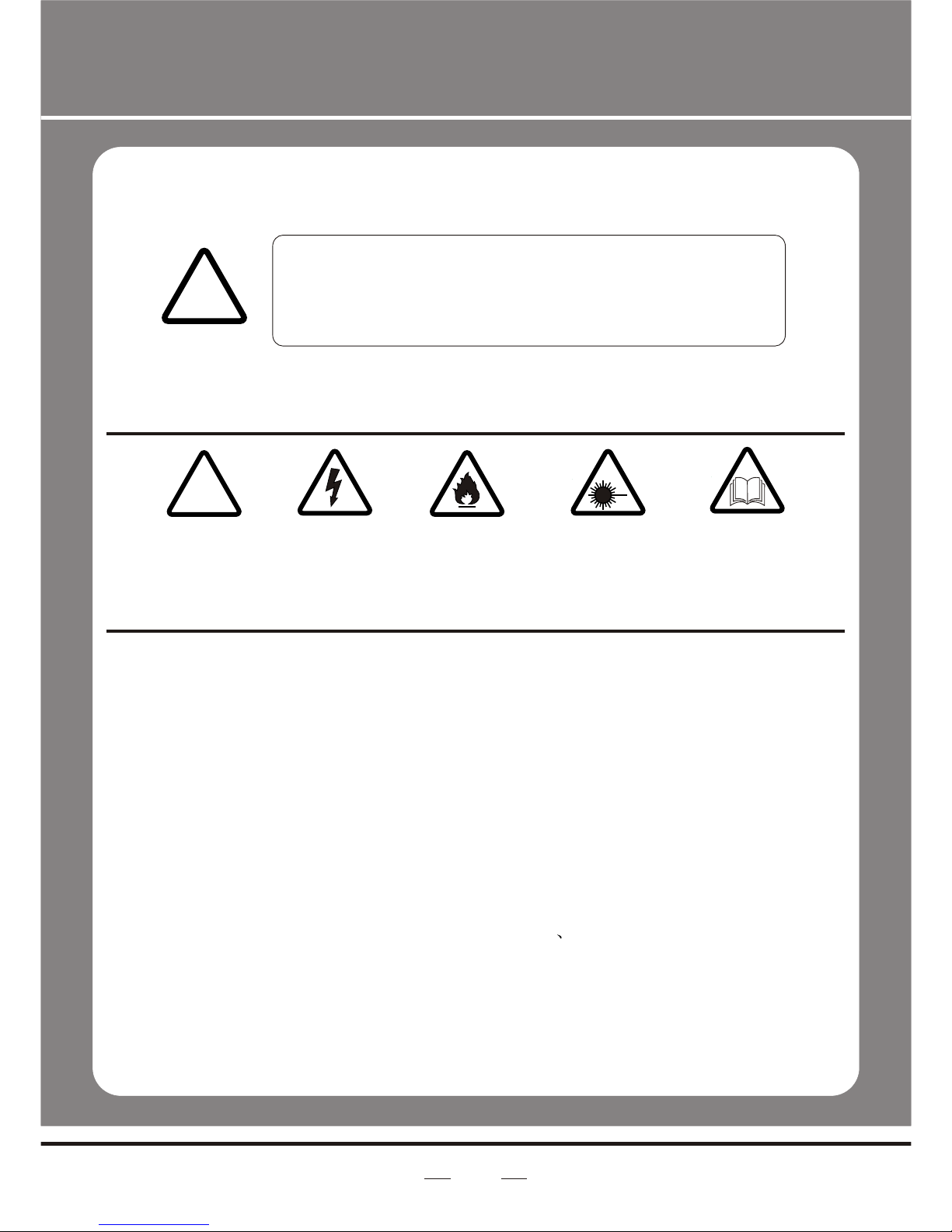
The following symbols are used to identify important safety information on the
product and inthis manual:
!!
DANGER!
Safety hazard.
Risk of severe
injury or death
DANGER!
Hazardous
Voltage. Riskof
lethal or severe
electric shock.
WARNING!
Fire hazard
WARNING!
LED light
emission. Risk
of eye injury.
WARNING!
Refer to user
=This light belongsto grade Iprotection device, thereforethe light mustconnect
to the earthexcellently. And thepower connection mustbe operated bythe
professional technician.
=Make sure thatthe working voltagewill not higheror lower thanthe rated value.
=Make sure thatthe cable didn'tbe damage orlacerated by sharp.
=The light mustbe power off when it's standing idle or before clearing.
=The cable mustwith plug, andyou must pullout the cableby handle theplug.
=Please be carefulwhen installing thelighting. Never touchthe bared cable,or
it will causethe deadly electricshock.
=Please use thesuitable and safecable to connectthe light.
=Please never remodelthe light randomly, we willnot take theguarantee for the
faulty and damagewhich caused bydismantle repair or remodelof the
nonprofessional person.
=Maximum ambient temperature40°C. Do notoperate fixture attemperatures
higher than this.
=Never connect thedevice to adimmer pack.
=Do not daisychain power tomore than 8units @ 120Vand 15 units@ 230V.

4
2.INTRODUCTION
Specifications
lVoltage Rating: AC100V 240V 50-60Hz
lPower Rating:50W
lLED Quantity: 12pcs 3 in1 LEDs(RGB)
lLED: 400mA
lBeam Angle: 20°/30°/40°
lIngress Protection: Ip20
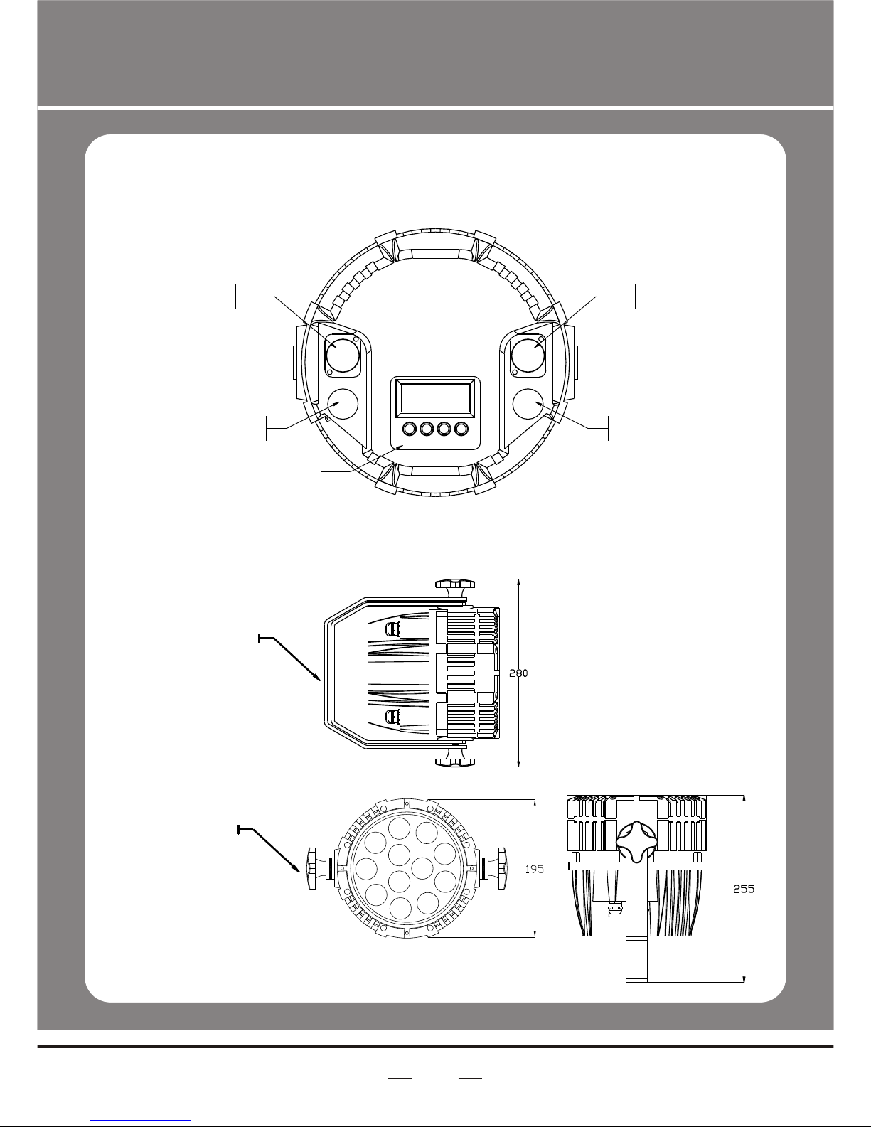
lProduct Size: 295x195 x255mm
lPackage Size: 350x260x320mm
lN/W:4.6Kg
lG/W:5.6Kg
Features
lRGB color mixing with or without DMX controller
l5 distinct dimming curves
lLED display with password protection
lOperating Modes: DMX512Connection /Master &Slave...
lDMX Channels: 03CH/04CH/05CH/06CH
06 channels: Dimmer+RGB+Macro&AUTO + strobe
05 channels:RGB +Dimmer+strobe
04 channels:RGB +Dimmer
03 channels:RGB
5
Product Overview
Hanging
bracket/ floor
stand
Bracket
adjustment
knob
Power in Power out
DMX IN DMX OUT
Control board
Dimensions

6
3.SETUP
Installation Requirement
lThis product can be used in a variety of situations, can hang and put on
the ground.
lIf hanging the fixture for over head use, thenplease follow thebelow steps.
lPlease choose thesuitable location toput or hangthe light wheninstalling it.
Youmust use the exclusive clamp hanger and screw when hanging it, and
make sure the weight of the light is within limits of the hanger.
lPlease make sure without any flammable objects within 0.5m when
installing the light.
lThe installation should be operated by professional person; any irregular
installation will cause the body injury or equipment damage.
lBlock access belowthe work areaand use suitable and stable platform
when installing or servicing fixture.
Hanging Clamp
Note: sold
separately
Safety Cable
Note: the cablemust be
secured through the heat
sink ventilation
passageway.
7
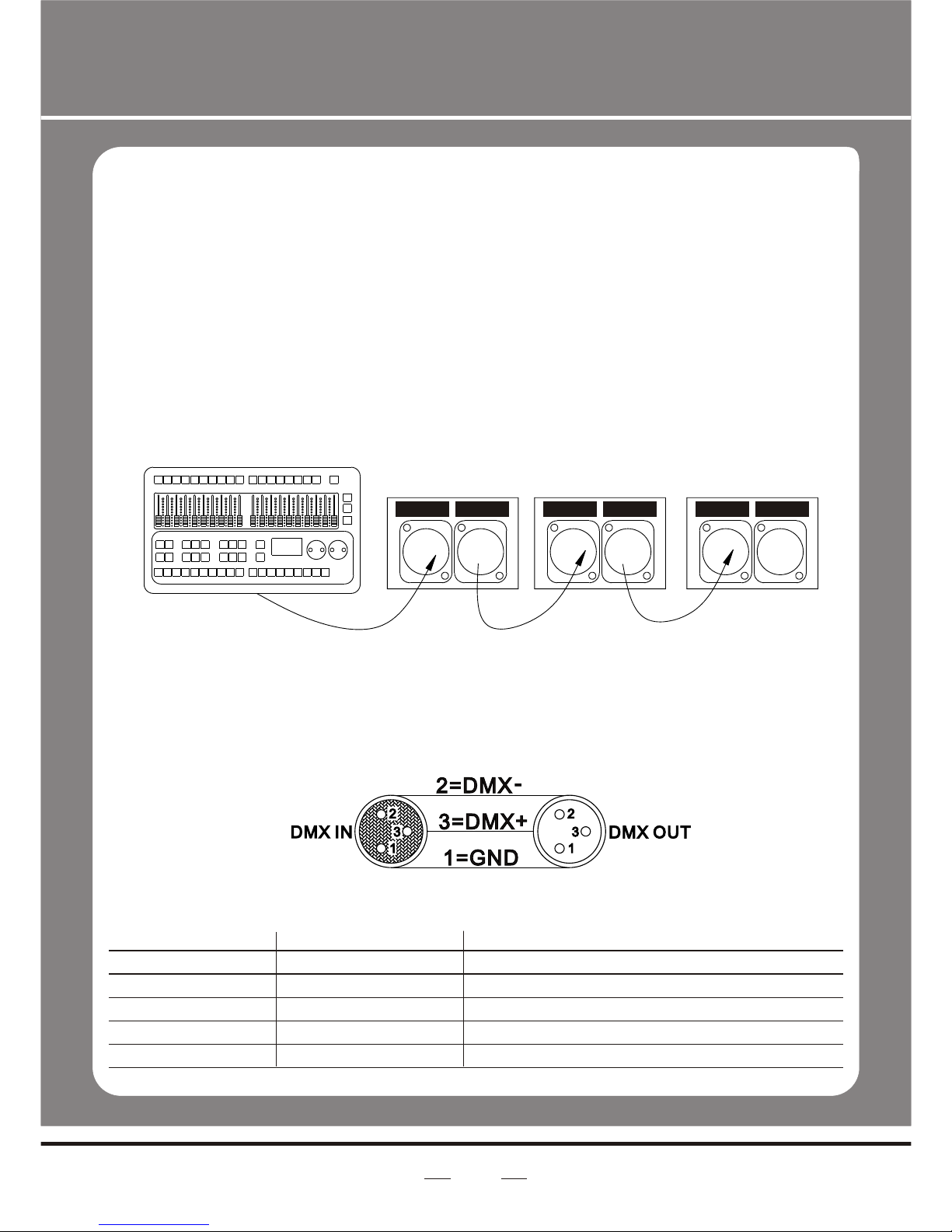
Connection of DMX Signal Wire
1Please use the fixture controller wire specially when use the DMX512
Controller. Connectthe (male) 3pin connector side of the DMX cable to
the output (female) 3 pin connector of the first fixture.
2Connect the endof the cablecoming from the first fixture which will have
a (male) 3pin connector tothe input connector of the next fixture
consisting of a (female) 3 pin connector. Then, proceed to connect from
the output as stated above to the input of the following fixture and so on.
3This product can be connected numerous lamps in series without the
need for the signal amplifier; the signal will not be weakened.
DMX IN DMXOUT DMX IN DMXOUT DMX IN DMXOUT
3-PIN TO 5-PIN CONVERSION CHART
Note! If you use a controller with a 5 pin DMX output connector, you will
need to usea 5 pin to 3 pin adapter.
Conductor
Ground/Shield
Data ( -) signal
Data ( +) signal
Do not use
Do not use
3 Pin Female(output)
Pin 1
Pin2
Pin 3
5 Pin Male(Input)
Pin 1
Pin2
Pin 3
Do not use
Do not use
3 PIN TO 5 PIN CONVERSION CHART

BUTTON
MENU
DOWN
UP
ENTER
FUNCTION
Exits from thecurrent menu or function
Navigates downwards through the menu list and decreases the numeric
value when ina function
Navigates upwards through the menu list and increases the numeric
value when ina function
Enables the currently displayed menu or sets the currently selected
value in tothe selected function
4.OPERATING INSTRUCTIONS
Control Panel Functions
8
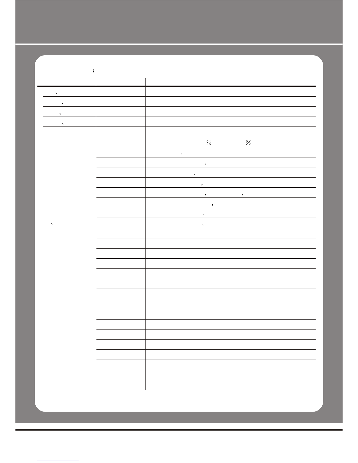
MENU

9
OFF
DIM(1-4)
Password
V402
RED
GRED
BLUE
STRB
TIME
FADE
ON
30S
PR00
01~09
custom
SC00
01~30
scene
Pr10
custom
SC00
01~90
scene
MAIN
FUNCTION
STAT
AUTO
DMX
RUN
PERS
SET
EDIT
DISP
SUB-
FUNCTION
D000
R000
G000
B000
S000
At00
Pr00
DMX
SLAV
03CH
04CH
05CH
06CH
DIM
REST
VER
SELECTION
000~255
(0 ~ 100%)
00~20
01~10
01~10
001 ~ 512
INSTRUCTION
User can combineRED, GREEN and
BLUE to generate acustom color
Select strobe frequency
10 auto programsavailable
chose program from10 “EDIT”
Set DMX startaddress
Sets the operatingmode for thefixture:to
receive signal froma DMX controller
(DMX) .receive signalor Download
programs from Masterfixture. (Slave)
03 channels RGB
04 channels Dimmer+RGB
05 channels Dimmer+RGB+ Strobe
06 channels Dimmer+RGB...
"Off" meansselect linear dimming,or
choose dimmer 1-4to control thedimming
speed, dimming 1of the fastestdimming
curves, 4 forthe most slowlydimming curve
Reset factory defaults
Version number
User can combineRED, GREEN, and
BLUE to generatea custom color
(0~20Hz)Select strobe frequency
(0~255) step time
transition time oflast step tocurrent step
Display is alwayson
Display switches off and goes into
Sleep mode if the controls havenot
been pressed for30 seconds
Menu Map

10
Operating instructions
1 Factory reset
SET ÜREST Ü{UP UP DOWN DOWN}Ü{ENTER}
Note: The password is permanentlyset as {UP UP DOWN DOWN}
Then press ENTERbutton
1 Custom program
EDIT ÜPR01 ÜPSC01
1Press MENU button until EDIT is displayed, pressENTER access programmode.
2Select the programyou'll edit by pressing UP/DOWN buttons. The available
range is o1-10.
3Select the stepyou'll edit by pressing UP/DOWN buttons, and then press
ENTER button accessprogram.
When 'R000' displayon the screen, press the UP/DOWN button to choose the value.
Repeat this stepto edit the value of 'G000', 'b000', 'S000', 'T000' and 'F000'.
Please pay attentionfor the 'S' is the rate of strobe. 'T' is the operating time of the
present step, thevalue is between 0 to 255. 'F' is the transitional time from previous
step to presentstep. The transitional time is the quickest when the FADE is 0.
Notice: Please operatethe program in turn, from the 01st step to the 30th step.
When the operatingprogram less than 30 steps, please set the final step value be 0
4Repeat step 3till complete programming.
5Exit program modeby pressing MENU buttons three times.
DMX512 Controller Mode
1 Setting DMX512 Address
DMX Ü001--512
Access control panelfunction by pressingMENU until DMX is displayed.
Press ENTER, addor reduce channelsby pressing UP/DOWNbetween 001 and 512.
Press MENU to exit.
2 Setting Channels
PERS Ü03CH 04CH 05CH 06CH
Access control panelfunction by prekssing MODE until PERS is displayed.
11
Channel
1 Dimming
2 RED
3 Green
4 Blue
5 Macro color
control& atuo
Value
000~255
000~255
000~255
000~255
0-4
5
6-19
20-24
25-49
50-59
60
61-74
75
76-84
85-89
90-94
95-99
100-104
105-109
110-114
115-119
120-124
125-129
130-134
135-139
140-144
145-149
150-154
155-159
160-164
Description
0-100%
0-100%(Or STEP TIME whenCUS.01-10 is activated)
0-10 0%(Or FADE TIMEwhen CUS.01-10 isactivated)
0-100%
No Function
BLUE 100%,RED90 ,GREEN97 ,
BLUE100% RED &GREEN DOWN
Purple (BLUE100% RED UP)
Red (RED100% BLUE DOWN)
Yellow (RED100% GREEN UP )
Lime(GREEN100% BLUE80% RED78%)
Green (GREEN100% RED & blue DOWN )
Teal (GREEN 10% BLUE 10%)
Cyan (GREEN UP BLUE UP)
Colour Scroll SnapSpeed 1 (Fastest)
Colour Scroll SnapSpeed 2
Colour Scroll SnapSpeed 3
Colour Scroll SnapSpeed 4
Colour Scroll SnapSpeed 5
Colour Scroll SnapSpeed 6
Colour Scroll SnapSpeed 7
Colour Scroll SnapSpeed 8
Colour Scroll SnapSpeed 9
Colour Scroll SnapSpeed 10
Colour Scroll SnapSpeed 11
Colour Scroll SnapSpeed 12
Colour Scroll SnapSpeed 13
Colour Scroll SnapSpeed 14
Colour Scroll SnapSpeed 15
Colour Scroll SnapSpeed 16
06 channels06 channels

12
Channel
5 Macro color
control& atuo
6 Strobe
Value
165-169
170-174
175-179
180-184
185-189
190-194
195-199
200-204
205-209
210-214
215-219
220-224
225-229
230-234
235-239
240-244
245-249
250-255
000-255
Description
Colour Scroll SnapSpeed 17 (Slowest)
Colour Scroll FADE Speed 1 (Fastest)
Colour Scroll FADE Speed 2
Colour Scroll FADE Speed 3
Colour Scroll FADE Speed 4
Colour Scroll FADE Speed 5
Colour Scroll FADE Speed 6
Colour Scroll FADE Speed 7
Colour Scroll FADE Speed 8
Colour Scroll FADE Speed 9
Colour Scroll FADE Speed 10
Colour Scroll FADE Speed 11
Colour Scroll FADE Speed 12
Colour Scroll FADE Speed 13
Colour Scroll FADE Speed 14
Colour Scroll FADE Speed 15
Colour Scroll FADE Speed 16
Colour Scroll FADE Speed 17 (Slowest)
Strobe(00~20Hz)
05 channels
Channel
1
2
3
4
5
Value
000~255
000~255
000~255
000~255
000~255
Description
Red
Green
Blue
Dimming
Strobe(00~20Hz)

13
04 channels
Channel
1
2
3
4
Value
000~255
000~255
000~255
000~255
Description
Red
Green
Blue
Dimming
03 channels
Channel
1
2
3
Value
000~255
000~255
000~255
Description
Red
Green
Blue
Master/Slave Control Mode
1 Setting master machine
Access control panelfunction by pressing MENU until AUTO is displayed.
Press ENTER, select ATXX OR PRXX by pressing UP/DOWNbuttons.
Press ENTER, andthen press MENU to exit.
You can choose ATXX pre-set programs, therange is o1--10 .
you can choose PRXX custom programs, therange is o1--10
2 Setting slave machine
Access control panel functionby pressing MENU until RUN is displayed.
Press ENTER, pressUP/DOWN buttons until the SLAV is displayed.
Press MENU return to MENU
3 Usage of Master/Slave
When two or more fixtures connected, you can set up the first machine asthe
Master and thefollowed fixtures asSlaves. The Master can choosepre-set programs ...
ATXX OR PRXX , all theslaves will followthe Master's operationsynchronously.
14
Symptom(s)
1 or moreLED's are
not illuminating
Breaker/Fuse keeps
blowing
Device has nopower
Fixture is not
responding to DMX
Loss of signal
Possible Solution(s)
Clean the fixtureregularly to avoidany such failure.This fixture is
convection cooled, whichmeans that ifthe surface iskept clean
and free ofdebris, then propercooling will beallowed to occur
An LED mayhave failed, resulting in an open circuit. In this event,
all of thered, green, or blue in a single module will no longer
illuminate. This does not meanthat all of the LEDs havefailed,
but the circuitis wired in series.
An LED mayhave failed, resultingin a shortcircuit. In thisevent, only
the single LEDwhich has failedwill no longerfunction. This does not
mean that allof the LEDshave failed, butthe circuit iswired in series.
-Note: In theevent of LED failure, a replacementLED PCB
assembly may bepurchased directly from Our company
Check total loadplaced on the electrical circuit
Check for ashort in the electrical wiring: internaland/or external
Check for poweron Mains
-Note: In theevent of autoswitching transformer failure, theunit
can be sentin for repair; however, a replacement part canbe
ordered directly from Our company
Check Control Panelsettings for correct addressing
Check DMX cables
Check polarity switchsettings on the controller
Check cable connections
Call service technician
-Note: In theevent of Display PCB failure, areplacement PCB
can be ordereddirectly from Our company
Use only DMXcables
Install terminator
Note: Keep DMXcables separated from power cables orblack
lights
5. APPENDIX
Service Maintenance Guide

15
Symptom(s)
COLOR-CON
Controller does not
function, or doesnot
function properly
Stand alone
operation
Possible Solution(s)
Make sure connectoris firmly connected to device
This fixture mustbe in the correct mode inorder to properly
respond to theCOLOR-CON controller. The correct mode is
“DMX” in the onboardControl Panel
This fixture hasbuilt-in, automatic programs that may be
triggered from theonboard Control Board

16
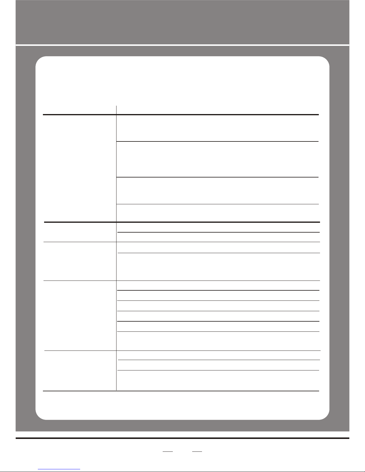
1
2
3
4
5
6
7
8
9
10
11
Description
Glass cover
LED Lens assembly
LED Metal-core PCBassembly
Power supply seat
XLR seat
LED Driver Board
House
Bracket Assembly
Bracket adjustment metalknob
Display PCB assembly
Electronic Transformer
Part Number
6P00118
6P00105
2P00106
5100103
5100102
2P00107
6P00118
5120117
5020105
2P00103
5080125
Blow-out Diagram.
Table of contents
Other CLF Lighting Equipment manuals


Popular Lighting Equipment manuals by other brands


LED2WORK
LED2WORK UNILED II operating instructions

Larson Electronics
Larson Electronics XLE-UVC-XX-SGKT-2X instruction manual

EuroLite
EuroLite RGB FLOOD-1500 DMX MK2 user manual

Chauvet
Chauvet Obsession LED user manual

Ballard Designs
Ballard Designs Klein Easel quick start guide

ABD Lighting
ABD Lighting ABD-LO9A user manual