F a s t l a n e®S w i m U n i t I n s t a l l a t i o n
5
poly pipe, but rather use a single length for each of the two hydraulic hoses that will run through them. The
goal is to provide an easy route for each of the two 3/8" hydraulic hoses — a route free of obstructions and
unlikely to bind. The hydraulic hoses may run on the surface outside the 1" poly pipe, but care must be
taken not to damage them. It is always best to use the 1" poly pipe provided as it protects the hydraulic
hoses from chafing as well as UV damage. The 1" poly pipe is chosen because of its slipperiness and the
ease with which the 3/8" hydraulic hose slides through it. At the same time, this 1" poly pipe can be easily
kinked which will make it difficult to slide the hydraulic hoses through later.
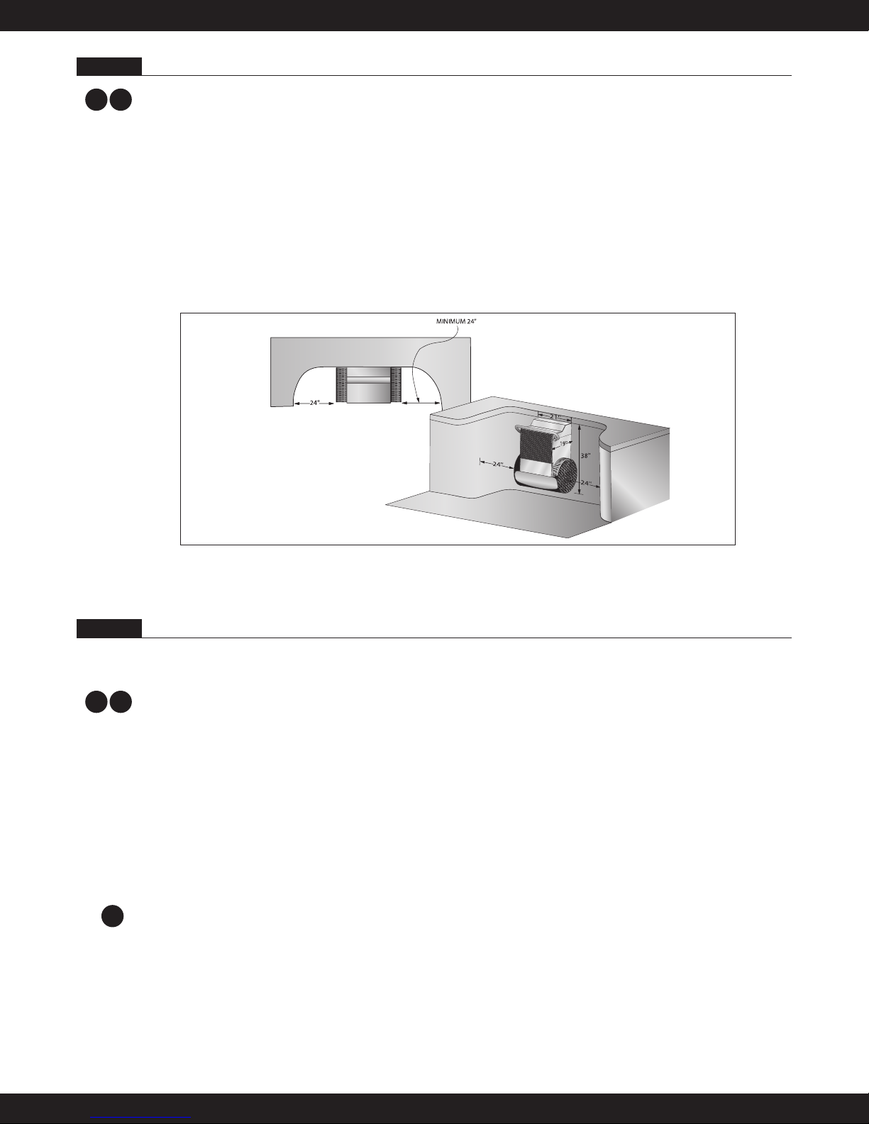
When planning for these two runs of 1" poly pipe, recognize that they penetrate the pool wall 1-1/2" above
the waterline and as a consequence will be flooded if the water level rises to that point. We strongly rec-
ommend that the 1" poly pipe rise to a point above which the water level will never rise to avoid any
potential flooding. This can be done during the 1" poly pipe run or back near the Power Unit. Tighten the
bracket liquid-tite fittings so that the 1" poly pipe is squeezed and water cannot leak around the 1" poly
pipe.
If you are concerned about subsidence and/or kinking, you may prefer to use a heavier 1-1/2" double run of
PVC flex pipe. To accomplish this, simply substitute the two couplings provided with the two (2) liquid-tite
fittings threaded into the PVC bracket, apply Teflon Tape to the couplings, and glue in the 1-1/2" PVC flex
pipe (refer to Photo 4.A.2).
NOTE: The pool builder/installer must decide if they will be using 1" poly pipe or 1-1/2" PVC flex
pipe BEFORE spraying gunite. Once the 1" poly pipe or 1-1/2" PVC flex pipe has been run, cut, and
trenched, the gunite can be sprayed.
If installing the provided 1" poly pipe (standard installation), the Wall Mount Fastlane ships with two
(2) 24' 6" rolls of 1" poly pipe. From the rear side of the pool, feed each 1" poly pipe into the liquid-tite fit-
tings and tighten the cord grip on the 1" poly pipe so that no water will pass between the 1" poly pipe and
the liquid-tite fitting. Unroll the 1" poly pipe to the location where the Power Unit will be located. The 1"
poly pipe is 6" shorter than the standard length of hydraulic hoses provided. As you run the 1" poly pipe, be
certain it does not kink. To ensure you have sufficient lengths of hydraulic hoses to make the necessary
connections to the Power Unit, cut off approximately 3' of each 1" poly pipe. The 1" poly pipe will need to
exit the ground near the Power Unit. If you find the 1" poly pipe is not long enough to reach the Power
Unit, a junction box and additional hydraulic hoses will need to be ordered and installed. In this case, DO
NOT CUT the length of the 1" poly pipe. Refer to Section 5 for additional information.
If installing the 1-1/2" PVC flex pipe, remove the two (2) 1-1/4" liquid-tite fittings from the wall mount
bracket. Thread and adhere with Teflon tape the two (2) 1-1/2" NPT male/slip female PVC fittings into the
wall mount bracket. Unroll the 1-1/2" PVC flex pipe from the wall mount bracket to the Power Unit. The
PVC flex pipe should exit the ground near the Power Unit. Each section of the PVC flex pipe should be no
longer than 21 feet. This will leave enough hydraulic hose to connect to the Power Unit. If you find that 21
feet of the PVC flex pipe is not long enough to reach the Power Unit, a junction box and additional hy-
draulic hoses will need to be ordered and installed. Refer to Section 5 for additional information.
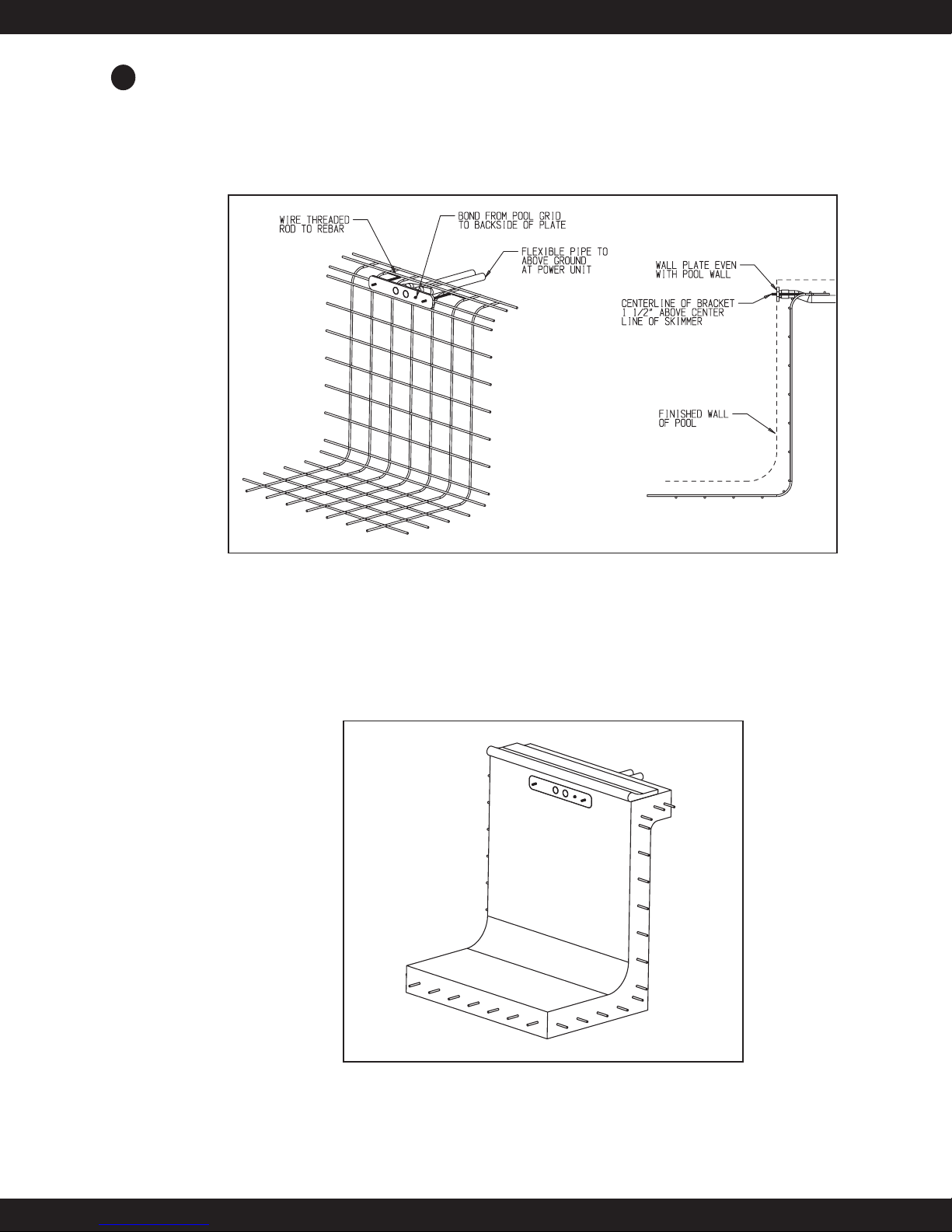
3/8" Stainless Steel Mounting
Rod. Firmly secure these
rods to the rebar grid.
These 1-1/2" couplings may
be used if you choose to use
1-1/2" PVC flex pipe rather
than the 1" poly pipe as your
conduit to the Power Unit
and junction box.
Example of 1-1/2"
PVC Flex Pipe
Bracket Plate
Bonding
Lug Set
Hang and secure Fastlane
on these SS threaded rods.
Wall Mount Fastlane Bracket.
Install this side flush with the
finished pool surface.
Attach SS bonding wire from
inside the Fastlane housing to
the bonding lug.
Cover PVC end with duct tape
to prevent gunite from clogging
the PVC.
Photo 4.A.2
W