Click 'N Carve 8403 User manual


Index
Chapter 1 Introduction ............................................................................1-1
Chapter 2 Safety Instructions ................................................................2-1
2-1 Safety Regulation and Notice ..........................................................2-1
2-2 Electrical Requrements ...................................................................2-3
2-3 Wiring Diagram ...............................................................................2-4
2-4 Extension Cords ..............................................................................2-5
2-5 Grounding Instructions ....................................................................2-6
Chapter 3 Hardware Features ...............................................................3-1
Chapter 4 Item Included with the Engraver ..........................................4-1
Chapter 5 Software Installation .............................................................5-1
5-1 Change User Account Control settings ...........................................5-1
5-2 EDIT Installation ..............................................................................5-3
5-3 CNC Installation ..............................................................................5-7
Chapter 6 EDIT Application Instructions .............................................6-1
6-1 Knowing the Work Region ...............................................................6-2
6-1-1 Menu Introduction ..................................................................6-2
6-1-2 EDIT Tool List .........................................................................6-4
6-1-3 Working Area .........................................................................6-5
6-1-4 Output Setting Area ...............................................................6-5
1. Output Setting ..................................................................6-5
2. 3D View ............................................................................6-9
3. G-Code Transfer ...............................................................6-9
4. Recorder List .....................................................................6-9
6-1-5 Document Information ..............................................................6-9
6-2 Description of File Format .............................................................6-10
6-2-1 File Formats can be Opened and Saved ...............................6-11
6-2-2 Resolution ..............................................................................6-11
6-2-3 Denition of Color Tone .......................................................... 6-12
6-3 Denition of Tool ............................................................................ 6-13
6-3-1 System Preset Tool ................................................................ 6-13
6-3-2 Tool added by User ................................................................ 6-14
6-3-3 Characteristics of Each Type of Tool ......................................6-18
6-4 Examples ......................................................................................6-19
6-4-1 Application : Photo engraved on White Plastic Material
(acrylic) ..............................................................6-19
6-4-2 Application : Photo engraved on Semi-transparent Dark
Color Plastic Materials (acrylic) .........................6-22
6-4-3 Application : Carving a Human Face on Wood Material ........6-25
6-4-4 Frame .....................................................................................6-31
6-5 Software Error Messages and Troubleshooting ............................6-34
6-6 Frequently Asked Questions (FAQ) ...............................................6-35
Important: You should turn off "sleep", "hibernate" and “hybrid sleep" mode in
your computer before engraving, or this will affect engraving
operation.
CNC software can supported the le format that created by Vectric,
ArtCAM, Bmp software. Please save the le in G-Code(mm),
G-Code(inch), G-Code Arcs(mm) or G-Code Arcs(inch) format.
EDIT and CNC software require a PC that runs Windows XP,
Windows 7 or Windows Vista.

Chapter 7 Positioning and Connecting the Engraver .........................7-1
7-1 Placing the Engraver .......................................................................7-1
7-2 Connecting the Power Cord ............................................................7-3
7-3 Connecting the Engraver to the Computer ......................................7-3
Chapter 8 Knowing the CNC Work Region ..........................................8-1
8-1 Menu Introduction ............................................................................8-2
A. Menu Listing ..................................................................................8-2
B. Displays the G-Code Fields ...........................................................8-4
C. Main Function Area .......................................................................8-4
D. Information Fields ..........................................................................8-5
E. Coordinates ...................................................................................8-5
F . Manual Control Area ......................................................................8-5
G. Preview Window ............................................................................8-6
H. Spindle Speed ..............................................................................8-7
I . Feed Rate Speed .........................................................................8-7
8-2 Software Error and Warning Messages and Troubleshooting .........8-8
Chapter 9 Engraver Operation Guide ....................................................9-1
9-1 Environment Settings ......................................................................9-1
9-2 Controller and Hotkey Settings ........................................................9-3
9-2-1 Controller Functions .................................................................9-3
9-2-2 Controller and Hotkey Environment Settings ...........................9-3
9-3 Holding the Engraving Workpiece ....................................................9-7
9-3-1 Wood Material ..........................................................................9-7
9-3-2 Acrylic Material .........................................................................9-8
How to use Silicone Mat ..........................................................9-8
9-3-3 Other Material Stick on Support Board ....................................9-9
9-4 Use of Clamps ..............................................................................9-10
9-5 Tool Installation Procedure .............................................................9-12
9-6 Engraving Path Conrmation .........................................................9-13
9-7 Starting Point Set-up .....................................................................9-18
9-8 Engraving Debris Removal Steps .................................................9-19
9-9 Feed Rate Speed Adjustment Instructions ....................................9-20
Chapter 10 Application .........................................................................10-1
10-1 Photo Engraved ..........................................................................10-1
10-2 GO TO Z Application ....................................................................10-3
10-3 OFFSET Application ...................................................................10-5
Chapter 11 Maintenance and Cares ....................................................11-1
Chapter 12 Q & A ...................................................................................12-1
Chapter 13 Exploded Diagram and Parts List
...................................13-1
13-1 Exploded Diagram .......................................................................13-1
13-2 Parts List ....................................................................................13-2
13-3 Spare Parts ..................................................................................13-3
Chapter 14 Specification ......................................................................14-1

1
This Engraver is a computer controlled engraver which contents an user-
friendly software package and easy-to-operate engraver. This engraver is
ideal for novice who wants to learn CNC or school for education material or
hobbyist and artist for small production of their project. The only thing you
need is a computer and a digital photo that you want engraved on wood or
acrylic and that’s it!!!! Follow by step by step instruction and you can finish
your project with no sweat!
Please read and follow all Safety Regulation and Operating Instructions
before turning on this engraver. If you do not understand any statement,
please contact the authorized dealer or service center.
The data and information in this manual may be subject to change without any
prior notice.
Please keep the carton and packaging for further servicing.
Chapter 1 Introduction

2-1
READ AND SAVE ALL INSTRUCTIONS FOR FUTURE REFERENCE.
Warning Label
The warning label as below will put on the engraver which indicate hazard
and understand the graphic on it. DO NOT remove this warning label from the
engraver.
Machine safety symbol is to remind operator to pay attention on it.
About Warning and Danger symbol
● Warning: a warning symbol means the presence of a hazard that has the
potential of causing moderate or minor personal injury.
● Danger: a danger symbol means the presence of a hazard that has the
potential of causing death or serious personal injury.
1. KEEP WORK AREA CLEAN. Cluttered areas and benches invite injuries.
2. GUARD AGAINST ELECTRIC SHOCK. Prevent body contact with
grounded surface. For example: pipes, radiators, refrigerator enclosures.
3. WEAR EYE PROTECTION. Everyday eyeglasses only have impact
resistant lenses, they are NOT safety glasses.
4. WEAR FACE OR DUST MASK. Cutting dust may scatter, causing bodily
injury.
5. WEAR EAR PROTECTION. Prevent permanent hearing loss by wearing
ear protection. Power tools can generate high levels of noise.
6. SECURE WORK. Use clamps or a vise to hold work when practical. It’s
safer than using your hand.
7. WEAR PROPER APPAREL. Do not wear loose clothing, gloves, neckties,
rings, bracelets, or other jewelry which may get caught in moving parts.
No slip footwear is recommended. Wear protective hair covering to contain
long hair.
8. CONSIDER WORK AREA ENVIRONMENTS. Remove materials or debris
that may get turned by sparks. Don’t use in damp or wet locations, or in the
presence of explosive atmospheres (gaseous dust, fumes, or flammable
materials) Keep work area well lighted, don’t expose power tools in rain.
Please operate under temperature at 5°C~40 °C (41~104 °F) and within a
humidity of 35~80%
9. DON’T USE IN STORM OR LIGHTNING. Doing so might get an electric
shock or cause severe injury.
Chapter 2 Safety Instructions
2-1 Safety Regulation and Notice

2-2
10.AIR VENTILATED THE WORK AREA. Do not cover the air inlet by cloth or
paper or stack up items nearby the power tool.
11.KEEP CHILDREN AND VISITORS AT SAFE DISTANCE. To avoid
accident, keep all children and visitors should be kept safe distance from
the power tool.
12.CHILDREN OPERATES WITH ADULT SUPERVISION. Failure to do so
may result in injury.
13.MAKE WORKSHOP KID PROOF with padlocks, master switches, or by
removing starter keys.
14.STORE IDLE TOOLS. When not in use, tools should be stored in dry and
high or lock in a place that out of reach of children.
15.STALL ON A STABLE SURFACE. Failure to do so may result in falling of
the tool and leading to injury.
16.DON’T OVERREACH. Keep proper footing and balance at all times.
Engraved area cannot bigger than its capacity.
17.REMOVE ADJUSTING KEYS AND WRENCHES. Form habit of checking
to see that keys and adjusting wrenches are removed from tool before
turning it on.
18.DISCONNECT TOOLS FROM OUTLET. When it is not in use, before
changing accessories, or performing recommended maintenance,
disconnect tools from outlet.
19.DON’T FORCE TOOL. It will do the job better and safer at the rate for
which it was designed.
20.USE RIGHT TOOL. Don’t force small tool for attachment to do the job of a
heavy-duty tool. Don’t use tool for purpose not intended to.
21.CHECK DAMAGED PARTS. Before further use of the tool, a guard or
other part that is damaged should be carefully checked to determine
that it will operate properly and perform its intended function – check for
alignment of moving parts, binding of moving parts, breakage of parts,
mounting, and any other conditions that may affect its operation. A guard or
other parts that is damaged should be properly repaired or replaced.
22.STOP OPERATING WHILE IN AN ABNORMAL PHENOMENON (smoke,
burning odor, unusual sounds..etc). If above happened, please stop
operating immediately and contact your authorized dealer or service
center.
23.AVOID LEAVE A RUNNING TOOL UNATTENDED. Never leave the tool
until it comes to a complete stop.
24.AVOID UNINTENTIONAL STARTING. Make sure switch is in off position
before plugging in.
25.USE RECOMMENDED ACCESSORIES. Consult the owner’s manual for
recommended accessories. The use of improper accessories may cause
risk of injury to persons.
26.DO NOT HOLD OR STRESS THE SPINDLE DURING OPERATION.
Doing so will accelerate wear and cause premature failure.
27.MAINTAIN TOOLS WITH CARE. Keep tools sharp and clean for best
and safest performance. Follow instructions for lubricating and changing
accessories. Inspect tool cords and extension cords periodically and if
damaged, please contact authorized dealer or service center and have it
repaired by them.

2-3
28.USE THE PROPER EXTENSION CORD. Only use the extension cord in
good condition. Never use more then one extension cord. Do not use the
extension cord with other electric products. Read “2-4 EXTENSION CORD”
section for more information.
29.DO NOT UNPLUG THE POWERCORD PLUG WITH WET HANDS. Doing
so may result in electrical shock.
30.DO NOT DISASSEMBLE, REPAIR, OR MODIFY. Doing so may lead to fire
or abnormal operation resulting in injury.
31.ONLY USE ATTACHED POWERCORD. Failure to do so may lead to fire or
electrical shock.
32.POWECORD MUST GROUNDED. Failure to do so may lead to fire or
electrocution.
33.DON’T ABUSE CORD. Never yank the cord to disconnect it from
receptacle, disconnect it from receptacle by hands. Keep cord away from
heat, oil and sharp edges. Do not destroy, modify, bend, twist, pull, binding
or pinching it nor place any object of weight on it .Inspect cords regularly
and repair or replace if damaged.
34.STAY ALERT Watch what you are doing. Use common sense. Do not
operate tool when you are tired.
35.DO NOT OPERATE ANY POWER TOOL WHILE UNDER THE
INFLUENCE OF DRUGS, ALCOHOL, OR ANY MEDICATION AFFECTING
ALTERNESS.
36.The usage of emergency stop: If there is any problem during engraving
and need to stop immediately, please press the emergency stop button to
stop the machine and motor to protect the operator.
● CONNECTING TOOL TO POWER SOURCE OUTLET. This machine
source must be
grounded while in use to protect the operator from electrical shock.
● In the event of a malfunction or breakdown, grounding provides a path of
least resistance for electrical current to reduce the risk of electrical shock.
This tool is equipped with an electric cord having equipment grounding
conductor and a grounding plug. The plug must be plugged into a matching
outlet that is properly installed and grounded in accordance with all local
codes and ordinances.
● Do not modify the plug provided if it will not fit the outlet. Have the proper
outlet installed by a qualified electrician.
● Improper connection of the equipment-grounding conductor can result in a
risk of electric shock. The conductor with insulation having an outer surface
that is green (with or without yellow stripes) is the equipment-grounding
conductor. If repair or replacement of the electric cord or plug in necessary,
do not connect the equipment – grounding conductor to a live terminal.
● Check with a qualified electrician or service personnel if the grounding
instructions are not completely understood, or if in doubt as to whether the
tool is properly grounded.
● Use only 3-wire extension cords that have 3-prong grounding plugs and
3-pole receptacles that accept the tool’s plug.
● Repair or replace damaged or worn cord immediately.
● Only UL Listed extension cords should be used with this product.
2-2 Electrical Requrements

2-4
● Improper use of extension cords may cause inefficient operation of your
tool, which can result in overheating. Be sure your extension cord is rated
to allow sufficient current flow to the motor. For the proper gauge for your
tool, see EXTENSION CORDS section below.
● Do not let your fingers touch the terminals of plug when installing or
removing the plug to or from the outlet.
● If not properly grounded, this power tool can incur the potential hazard of
electrical shock particularly when used in damp locations or in proximity to
plumbing.
2-3 Wiring Diagram
.
o

2-5
2-4 Extension Cords
WARNING:
To avoid permanent motor damage you must use the correct extension cord.
Never use more than one extension cord at a time.
Use proper extension cord and make sure your extension cord is in good
condition. When using an extension cord, make sure all cords are no smaller
than a #18 gauge and equipped with 3 prong plugs. Use of anything smaller
may result in the overheating or burn out of the motor. It is recommended to
have an electrician check the incoming voltage prior to usage to ensure safe
and efficient use. The smaller the gauge numbers the heavier the cord.
1. Use only extension cords that are intended for outdoor use. These
extension cords are identified by a marking "Acceptable for use with
outdoor appliances; store indoors while not in use." Use only extension
cords having an electrical rating not less than the rating of the product.
Do not use damaged extension cords. Examine extension cord before
using and replace if damaged. Do not abuse extension cords and do not
yank on any cord to disconnect. Keep cord away from heat and sharp
edges. Always disconnect the extension cord from the receptacle before
disconnecting the product from the extension cord.
2. WARNING - To reduce the risk of electrocution, keep all connections dry
and off the ground. Do not touch plug with wet hands.
3. Ground Fault Circuit Interrupter (GFCI) protection should be provided
on the circuit(s) or outlet(s) to be used for the tile saw. Receptacles
are available having built-in GFCI protection and may be used for this
measure of safety.

2-6
2-5 Grounding Instructions
This tool is equipped with an electric cord having an equipment-grounding
conductor and grounding plug. The plus must be plugged into a matching
outlet that is properly installed and grounded in accordance with all local
codes and ordinances.
Do not modify the plug provided-if it will not fit the outlet, have the proper
outlet installed by a qualified electrician.
Improper connection of the equipment-grounding conductor can result
in a risk of electric shock. The conductor with insulation having an outer
surface that is green with or without yellow stripes is the equipment-
grounding conductor. If repair or replacement of the electric cord or plug
is necessary, do not connect the equipment-grounding conductor to a live
terminal.
Check with a qualified electrician or service personnel if the grounding
instructions are not completely understood, or if in doubt as to whether the
tool is properly grounded.
Repair or replace damaged or worn cord immediately.
B. Grounded, cord-connected tools intended for use on a supply circuit
having a nominal rating less than 150volts; This tool is intended for use
on a circuit that has on outlet that looks like the one shown in figure A in
illustration 2. A temporary adapter, which looks like the adapter shown
in figure B in illustration 2, may be used to connect this plug to a 2-pole
receptacle as shown in figure B in illustration 2 if a properly grounded
outlet is not available. The temporary adapter should be used only until
a properly grounded outlet can be installed by a qualified electrician. The
green-colored rigid ear, lug, and the like, extending from the adapter must
be connected to a permanent ground such as properly grounded outlet
box.
A. All grounded, cord-
connected tools:
In the event of
a malfunction or
breakdown, grounding
provides a path of least
resistance for electric
current to reduce the risk
of electric shock.

3-1
Chapter 3 Hardware Features
Front View:
Spindle Cover
Cutting Tool
Working Table
Emergency Stop
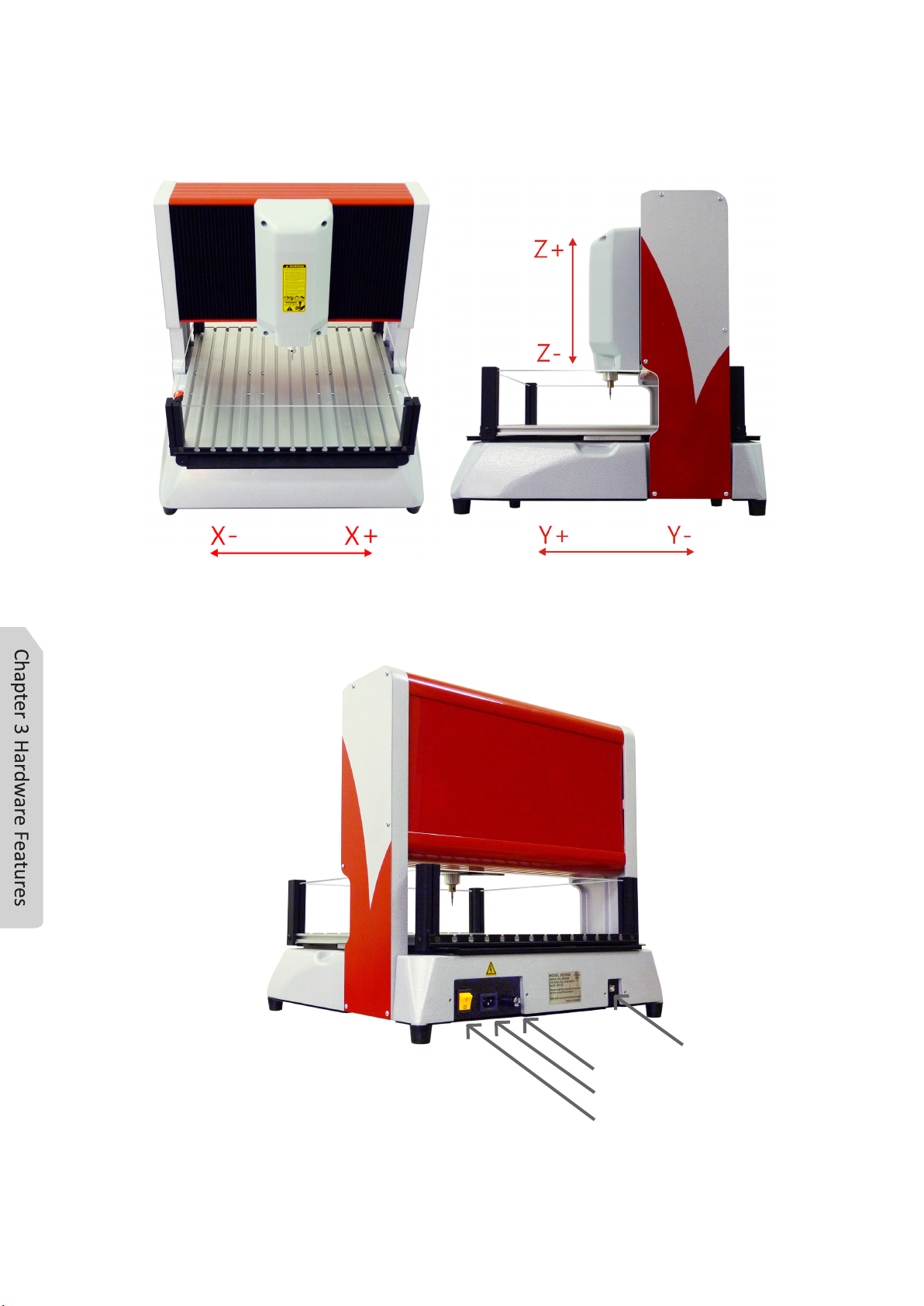
3-2
X, Y, Z axis direction:
Rear View:
Fuse
AC Power Supply
Switch
USB Port

3-3
Air Outlet:
Bottom Air Outlet
!
AIR VENTILATED THE WORK AREA.
Do not cover the air inlet by cloth or paper or stack up items nearby the
machine.

4-1
Chapter 4 Item Included with the Engraver
Power Cord × 1 USB Cable × 1 Controller × 1
Allen Key_2.5mm × 1 Silicone Mat × 1
Support Board × 1 Thin Paper × 1
( for Starting Point set-up)
BravoProdigy Software
Installation Disc × 1
Operating Instructions × 1 Engraving Material
Tungsten Carbide Tool × 2
Clamp Set
Small ×2 Big ×2

5-1
Chapter 5 Software Installation
5-1 Change User Account Control Settings :
If you are WINDOWS 7 or WINDOWS VISTA user, please modify the Setting
in UAC (User Account Control) when you install this software. The simple
procedure is as follow: [Start] -> [Control Panel] -> [[User Accounts] ->
[Change User Account Control settings] -> Adjust the slider to [Never notify] -
> [OK].
The detailed modify method is as follows:
1. Left click the Start button.
2. Open the Control Panel.
3. Click [User Accounts]

5-2
4. Click the [Change User Account Control settings]
5. WIN 7 user : Adjust the slider to [Never notify], then click .
Please reboot computer to complete this modification.
VISTA user : Uncheck the box for “ Use User Account Control (UAC)” and
then click .
Please reboot computer to complete this modification.
Note:For more information on how to change user account control setting,
please refer to your Laptop / Computer instruction manual.

5-3
5-2 EDIT Installation :
5-2-1 System Requirement for BravoProdigy EDIT:
5-2-2 EDIT Installation:
1. Place the BravoProdigy Installation Disc in the CD-ROM driver.
After inserting Installation Disc, the below image will pop up automatically.
If the installation program did not run automatically, please do as following:
Step1: Please open Windows Explorer or click Start-> (My) Computer, and
click “BravoProdigy Software” under “Devices with Removable
Storage” and right mouse click.
Step2: Choose “open” and double click “autorun.exe” to install.
The minimum requirement of computer is Pentium 4 2.6GHz RAM 1 GB.
Intel Pentium Duo-Core 3.0GHz RAM 2GB or better is recommended.
It is highly recommend not to using other software during engraving operation.
2.Click , set up by BravoProdigy Software
Setup Wizard. Please follow the instruction to install. If the software
wizard doesn’t appear automatically, then install by double-clicking
Software Disc.

5-4
4. Follow by BravoProdigy EDIT Software Setup Wizard. See image as below.
Press to process.
3. Please select the language and then click .

5-5
5. Copyright Agreement dialog will appear. Please read the Copyright
Agreement and fully understand. If you accept this Copyright Agreement,
please check “I accept the agreement” and press to continue.
6. Now, it will show the program location in the dialog. If you would like not to
select a different folder, please press after confirmation.

5-6
Note: If you want to change the location, press to change the
location of this software.
7. Press to install the software.
Table of contents


