Climate Wizard CW-H10 User manual

CW-H10, CW-H15 MOTOR
INSTALL GUIDE
1
CW-H10, CW-H15
862798-D AU US 1604
The motor frame is held in place by metal stops. Whilst
pulling on the inlet cone, carefully slide the motor frame
forwards and then up to clear the framework.
If required, a large flat head screwdriver may be inserted
between the motor frame and cooler body to gain
additional leverage.
Pull the motor out of the frame and clear of the cooler far
enough to gain access to the motor cable connections at
the back of the motor.
Remove the motor connection cover at the back of the
motor. Disconnect the motor cables (using a small flat
head screwdriver) and remove from the motor frame.
Move the old fan/motor assembly away from the cooler.
WARNING - ELECTRICAL WORK MUST ALWAYS BE
CARRIED OUT BY A QUALIFIED ELECTRICAL
WORKER !
Isolate the Cooler at the switchboard ensuring that the
circuit breaker or fuse cannot be turned on or re-installed
whilst work is being carried out on the cooler.
Step 1: Air Filter or Safety Grille Removal
Depending upon the options fitted, either the air
filter/cowling assemblies or inlet air safety grille will need
to be removed to allow access the motor front plate. Refer
to the installation, operation and maintenance manual for
instructions.
Before the existing motor can be removed, the excess
length of the motor power and control cables needs to be
fed into the inlet transition.
Remove the small side service door (control box side).
Identify and release the 2x cable glands fitted to the inlet
transition side wall as shown in Fig 1. Push all excess
length of these cables through the glands. There is no
need to remove the cables from the control enclosure.
Step 2: Release Excess Cable
1
Step 3: Remove Old Fan/Motor
Remove and discard the qty. 12 M6x16mm socket head
cap screws and flat washers (4 on side, 8 on face) from
the motor face plate as shown in Fig 2.
2
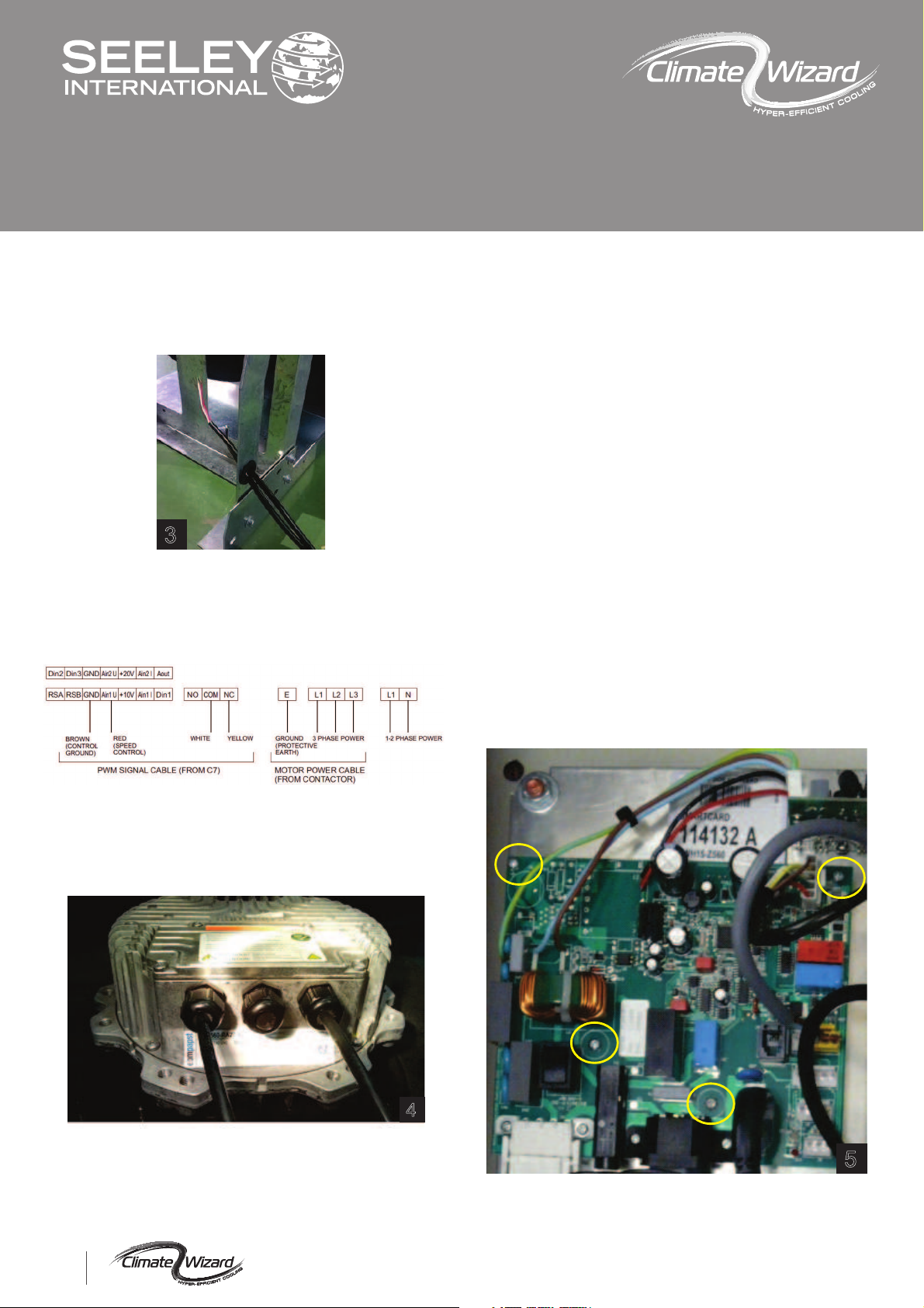
Step 4: Connect the New Motor
Motor Connection Schematics
Remove the new motor assembly from the crate. As items
may have moved in transit, check the fan/motor assembly
rotates freely and has even clearance between the inlet
cone and impeller.
Check the rating label on the NEW replacement motor and
confirm the motor model number is one of the following;
R3G560-RB32-01
(3~, 380-480V, 50/60Hz)
R3G560-RA25-21
(1~, 200-277V, 50/60Hz)
R3G560-AG31-11
(3~, 200-240V, 50/60Hz)
CW-H10, CW-H15 MOTOR
INSTALL GUIDE
3
2
CW-H10, CW-H15
862798-D AU US 1604
5
Step 4: Connect the New Motor cont.
Place the new fan/motor assembly near the cooler so that
the motor power and control cables can be connected.
Pass both cables through the large rubber grommet in the
motor frame as shown in Fig 3.
Remove the motor connection cover at the back of the
motor. Pass the motor power cable through the right hand
cable gland and the motor control cable through the left
hand cable gland. The middle cable gland is not used.
Wire the motor to the following schematic.
Ensure the cable glands are secure against the power
and control cables. Ensure the central connection has the
blanking plug fitted (refer Fig 4). Replace the connection
cover, applying a tightening torque of 3.5Nm to the
screws.
4
Zip-tie the cables to the motor frame where they pass
through the large grommet, leaving sufficient length of
cable to avoid any strain on the motor connection plate
glands.
Step 5: Fit the New Motor Assembly
Whilst taking care not to trap the motor power and control
cables, lift the motor/fan assembly into the cooler. As the
assembly is pushed fully back, slowly pull all excess cable
length through the 2x inlet transition glands.
Secure the motor/fan assembly with new Qty.12
M6x16mm Socket Head Cap Screws and Flat Washers,
applying a tightening torque of 5Nm.
Tighten the 2x cable glands in the inlet transition side wall.
Bundle and zip-tie all excess cable length inside the cooler
as shown in Fig 1.
Replace the small side service door, applying a coating of
anti-seize paste to the fasteners and a tightening torque of
3Nm.
Step 6: PCBA Replacement
Your motor replacement kit may contain a new PCBA.
This is required in instances where the replacement motor
is a newer model than the old motor. If no new PCBA has
been supplied, proceed to Step 7, otherwise complete this
step first.
Open the control enclosure and disconnect all cables from
the old PCBA. The PCBA is the larger of the two circuit
boards. Release the PCBA by removing the Qty. 4 M3x3
Pan Head Screw and Star Washers shown in Fig 5.
5
Fit the new PCBA, apply a tightening torque of 1Nm.
Reconnect all the previously removed cables.

CW-H10, CW-H15 MOTOR
INSTALL GUIDE
3
CW-H10, CW-H15
862798-D AU US 1604
Step 7: Smart Card Replacement
Your motor replacement kit will contain a new Smart Card.
Insert the new Smart Card into the PCBA with label facing
out as shown in Fig 5.
The new smart card contains the data required for the
new motor to function correctly and needs to be used
whether the PCBA has been replaced or not.
Step 8: Motor Ground Bond Test
WARNING –The ground bond test is an important
safety check. It confirms that the motor is well
connected to the cooler's ground pin.
As shown in Figures 6 and 7, connect an ohmmeter to the
cooler as follows;
Connect the first test lead to the controls enclosure cable
earth pin.
Confirm the measured resistance is 0.1 Ohms
(1000 Milliohms) or lower.
6
7
Connect the second test lead to the head of an inlet cone
fastener.
Step 8: Functional Test
WARNING –DO NOT OPERATE THE FAN WITHOUT A
SUITABLE GUARD. REFIT THE AIR FILTER FRAME OR
INLET AIR SAFETY GRILLE PRIOR TO STARTING
MOTOR.
Start the cooler in vent mode. Confirm that the fan starts,
rotates in a clockwise direction and the speed changes as
it is adjusted using the wall control.
Confirm there is no excessive vibration or unusual noise.
Step 9: Air Discharge Damper Setup
If removed in Step 1, fully re-fit the air filters and cowling
assemblies. Refer to the Installation, Operation and
Maintenance Manual for instructions.
In instances where the replacement motor is a newer
model than the old motor, it is likely that the new fan/motor
may have slightly different air flow performance. It is
strongly recommended that the airflow balancing
procedure found in the Commissioning Section of the
Installation, Operation and Maintenance Manual be
repeated using the following Pressure Settings appropriate
to your Climate Wizard Model;
CW-H10: 155 Pa (0.62 in wg static)
CW-H15: 190 Pa (0.76 in wg static)
CW-H15S: 120 Pa (0.48 in wg static)
CW-H15S (Winery): 165 Pa (0.66 in wg static)
Where different from the Installation, Operation and
Maintenance Manual, the Pressure Settings in this
installation guide takes precedence. This will ensure the
setup of the cooler is optimised for best cooling
performance.

CW-H10, CW-H15 MOTOR
INSTALL GUIDE
4
CW-H10, CW-H15
862798-D AU US 1604
AUSTRALIA
1300 650 399
1300 367 437
1300 650 644
Seeley International Technical Support
Seeley Spare Parts Distributors
Authorised Service Agents
(All regions outside Australia: For any inquiries, please contact your local Breezair
distributor)
- Failure to install and commission the product in compliance with these
instructions, or failure to do the job properly and competently, may void the
customer’s warranty. Further, it could expose the Installer and/or the Retailer to
serious liability.
WARNING
It is the policy of Seeley International to introduce continual product improvement.
Accordingly, specifications on this document are subject to change without notice.
Whilst every care has been taken to ensure data accuracy, Seeley International Pty
Ltd does not assume liability for any errors and or omissions.
Notes
Other manuals for CW-H10
2
This manual suits for next models
1
Popular Accessories manuals by other brands

Jupiter Avionics
Jupiter Avionics JA72-006 Installation and operating manual

Mr Safe
Mr Safe KB-350 user manual

LU-VE
LU-VE F31HC Series Installation, Operation, Service and Maintenance Instructions

Philips
Philips HF3519 user manual

Tripp Lite
Tripp Lite UPB-20K0-2U1C owner's manual

Sentera Controls
Sentera Controls FCMFFB-R Mounting and operating instructions


