ClimateMaster AHWG Series Guide
AHWG Remote Mount
Hot Water
Generator Module
for TTP Series
Outdoor Split Unit
Installation, Operation &
Maintenance Instructions
97B0080N01
Rev.: Feburary 10, 2016
Table of Contents
Model Nomenclature Example 3
Description and Installation Examples 4
Installation and Operating Instructions 5-8
Wiring and Electrical Data 9-10
Warranty 11
Revision History 12

This page was intentionally left blank.

3
Remote HWG
Rev.: Februrary 10, 2016
climatemaster.com
Model Nomenclature: for Remote
Hot Water Generator
AHWG 1
1 2 3 4 5
Accessory
AHWG = Accessory Remote
Hot Water Generator
Size
B
6
Revision
A
7
S
8 9
Future
Voltage
S
1 = Standard
B = Current Revision
SS = Standard
A = 115/60/1
G = 208-230/60/1
Remote HWG
Rev.: Februrary 10, 2016
4Geothermal Heat Pump Systems
Hot Outlet
to home
Insulated water lines -
5/8” OD, 50 ft maximum (one way) meters
[16mm OD, 15 meters maximum]
Powered
Water
Heater
Upper
element to
120 - 130°F
[49 - 54°C]
Lower
element to
100 - 110°F
[38 - 43°C]
Cold Inlet from
Domestic supply
Shut-off
Valve #4
Shut-off
Valve #3
Shut Off
Valve #2
Shut-off
Valve #1
Insulated water lines - 5/8” OD, 50 ft maximum (one way)
[16mm OD, 15 meters maximum]
Upper element to 130°F [54°C]
(or owner preference)
Cold Inlet
Hot Outlet to
house
Powered
Water Heater
Cold Inlet from
Domestic supply
Hot Outlet
Unpowered
Water Heater
Field Supplied 3/4” brass nipple and “T”
Lower element to 120°F [49°C]
Shut-off
Valve #1
Shut-off
Valve #4
Shut-off
Valve #3
Shut Off
Valve #2
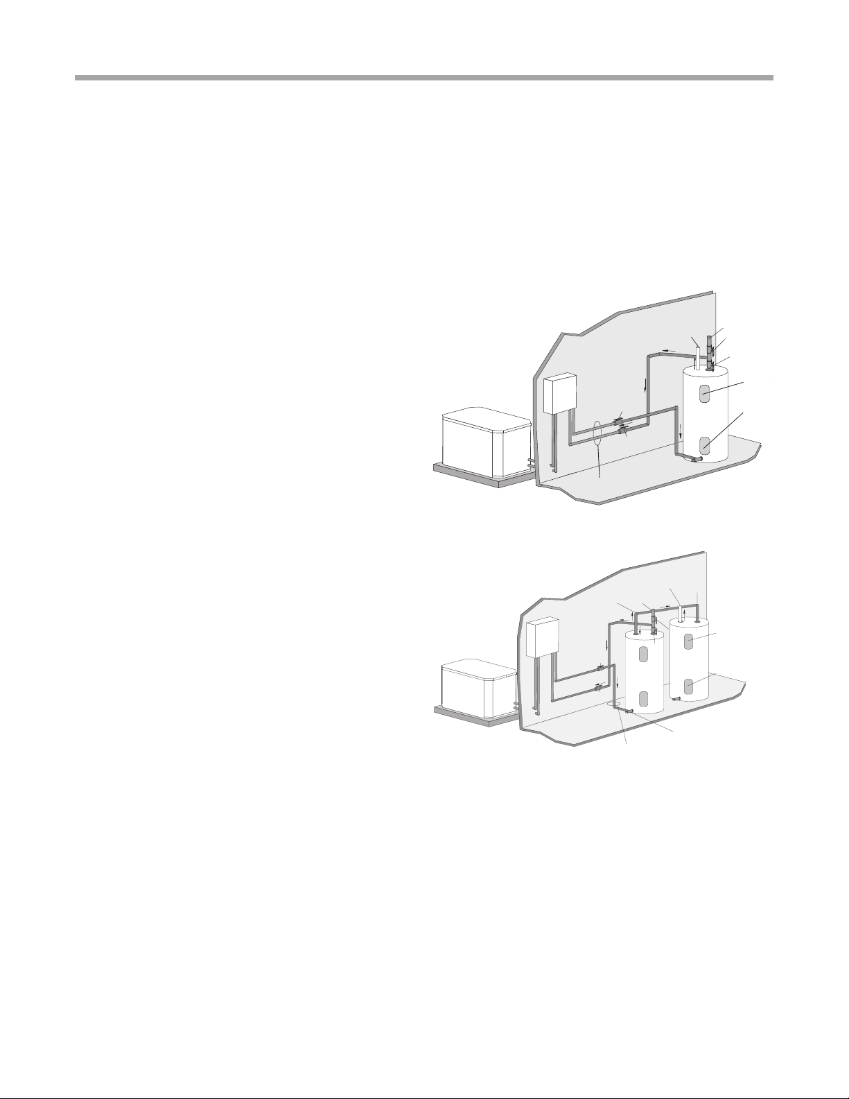
Figure 1: Typical HWG Installation (Outdoor Compressor
Section)
Figure 2: HWG Double Tank Installation (Outdoor Com-
pressor Section)
Hot Water Generator Module For
Outdoor Compressor Section
General Information
The HWG Module consists of an all-copper, vented double-
wall heat exchanger and a water-cooled bronze water cir-
culating pump. The pump is controlled by a microprocessor
in the HWG module. Power for the pump is provided from a
remote 115 or 230 vac power source.
The HWG (Hot Water Generator) or desuperheater option
provides considerable operating cost savings by utilizing
excess heat energy from the heat pump to help satisfy
domestic hot water requirements. The HWG may be active
throughout the year, providing virtually free hot water when
the heat pump operates in the cooling mode or hot water at
the COP of the heat pump during operation in the heating
mode. Actual HWG water heating capacities are provided in
the appropriate heat pump performance data.
The temperature set point of the HWG is eld selectable
to 125°F or 150°F . The 150°F set point allows more heat
storage from the HWG. For example, consider the amount
of heat that can be generated by the HWG when using the
125°F set point, versus the amount of heat that can be
generated by the HWG when using the 150°F set point.
In a typical 50 gallon two-element electric water heater
the lower element should be turned down to 100°F, or the
lowest setting, to get the most from the HWG. The tank will
eventually stratify so that the lower 80% of the tank, or 40
gallons, becomes 100°F (controlled by the lower element).
The upper 20% of the tank, or 10 gallons, will be maintained
at 125°F (controlled by the upper element).
Using a 125°F set point, the HWG can heat the lower 40
gallons of water from 100°F to 125°F, providing up to 8,330
btu’s of heat. Using the 150°F set point, the HWG can heat
the same 40 gallons of water from 100°F to 150°F and the
remaining 10 gallons of water from 125°F to 150°F, providing
a total of up to 18,743 btu’s of heat, or more than twice as
much heat as when using the 125°F set point.
This example ignored standby losses of the tank. When
those losses are considered the additional savings are even
greater.
Electric water heaters are recommended. If a gas, propane,
or oil water heater is used, a second preheat tank must be
installed (Figure 2). If the electric water heater has only a
single center element, the dual tank system is recommended
to insure a usable entering water temperature for the HWG.
Typically a single tank of at least 52 gallons (235 liters) is used
to limit installation costs and space. However, a dual tank, as
shown in Figure 2, is the most ecient system, providing the
maximum storage and temperate source water to the HWG.
It is always advisable to use water softening equipment on
domestic water systems to reduce the scaling potential and
lengthen equipment life. In extreme water conditions, it may
be necessary to avoid the use of the HWG option since the
potential cost of frequent maintenance may oset or exceed
any savings. Consult unit IOM for scaling potential tests.

5
Remote HWG
Rev.: Februrary 10, 2016
climatemaster.com
Hot Water Generator Module Refrigeration Installation
For Outdoor Compressor Section Only
Location/Mounting
The HWG module should be mounted indoors and as close
to the heat pump outdoor section as possible, in order to
minimize the length of refrigerant run. It is recommended that
the HWG module be mounted above the system compressor
in order to promote proper oil movement and drain-down.
This means that the HWG module can be wall mounted
in any orientation except for stubs up. Mounting should be
accomplished by fastening the HWG module cabinet to the
wall or other selected vertical surface. Mounting holes are
provided at the rear of the unit. Any fastener suitable for sup-
porting a 12 pound [5.4] vertical load is acceptable.
SPECIAL NOTE: The selected mounting location and
orientation must allow the circulator pump to be positioned
with the motor shaft horizontal. DO NOT install the Heat
Recovery Unit at on its back.
Refrigerant Line Installation
Before starting the installation into the refrigerant circuit,
inspect and note the condition and performance of the heat
pump. Disconnect power to the heat pump outdoor unit. Any
system deciencies must be corrected prior to installing the
HWG module. Addition of the HWG will not correct system
problems. Record the suction and discharge pressures
and compressor amperage draw. These may be used for
comparison with system operation after the refrigerant line
installation is complete.
Install the Add-On HWG Kit
Locate the HWG as close to the water heater as possible.
Install the lineset to the desuperheater valves in the out-
door compressor section and the refrigerant line connec-
tions on the HWG. Maximum length should be 30 feet one
way. Evacuate the lineset to 500 microns through the hot
gas valves in the outdoor unit. Open the HWG valves in the
compressor section up fully (and close the desuperheater
bypass valve). See Figures 3a through 3d. Check the lineset
for leaks. Verify that lineset tubing is completely insulated
with a minimum 1/2” thick closed cell and painted to prevent
deterioration of the insulation due to ultra violet light and
weather. Make the connections with high temperature solder
or brazing rod. The recommended line size is dependent on
the one way distance between the Hot Water Generator and
the compressor; and the size of the system. Use Figure 4 as
a guideline.
� WARNING! �
� CAUTION! �
� CAUTION! �
WARNING! The HWG module is an appliance that
operates in conjunction with the heat pump system, the
hot water system and the electrical system. Installation
should only be performed by skilled technicians with
appropriate training and experience. The installation must
be in compliance with local codes and ordinances. Local
plumbing and electrical building codes take precedence
over instructions contained herein. The Manufacturer
accepts no liability for equipment damaged and/or personal
injury arising from improper installation of the HWG module.
CAUTION! The HWG module must be installed in an area
that is not subject to freezing temperatures.
NOTICE! Make sure the compressor discharge line is
connected to the “Hot Gas In” stub on the Hot Water
Generator.
CAUTION! Locate Refrigerant lines to avoid accidental
damage by lawnmowers or children.
Remote HWG
Rev.: Februrary 10, 2016
6Geothermal Heat Pump Systems
Hot Water Generator Module Installation
Outdoor Compressor Section Only
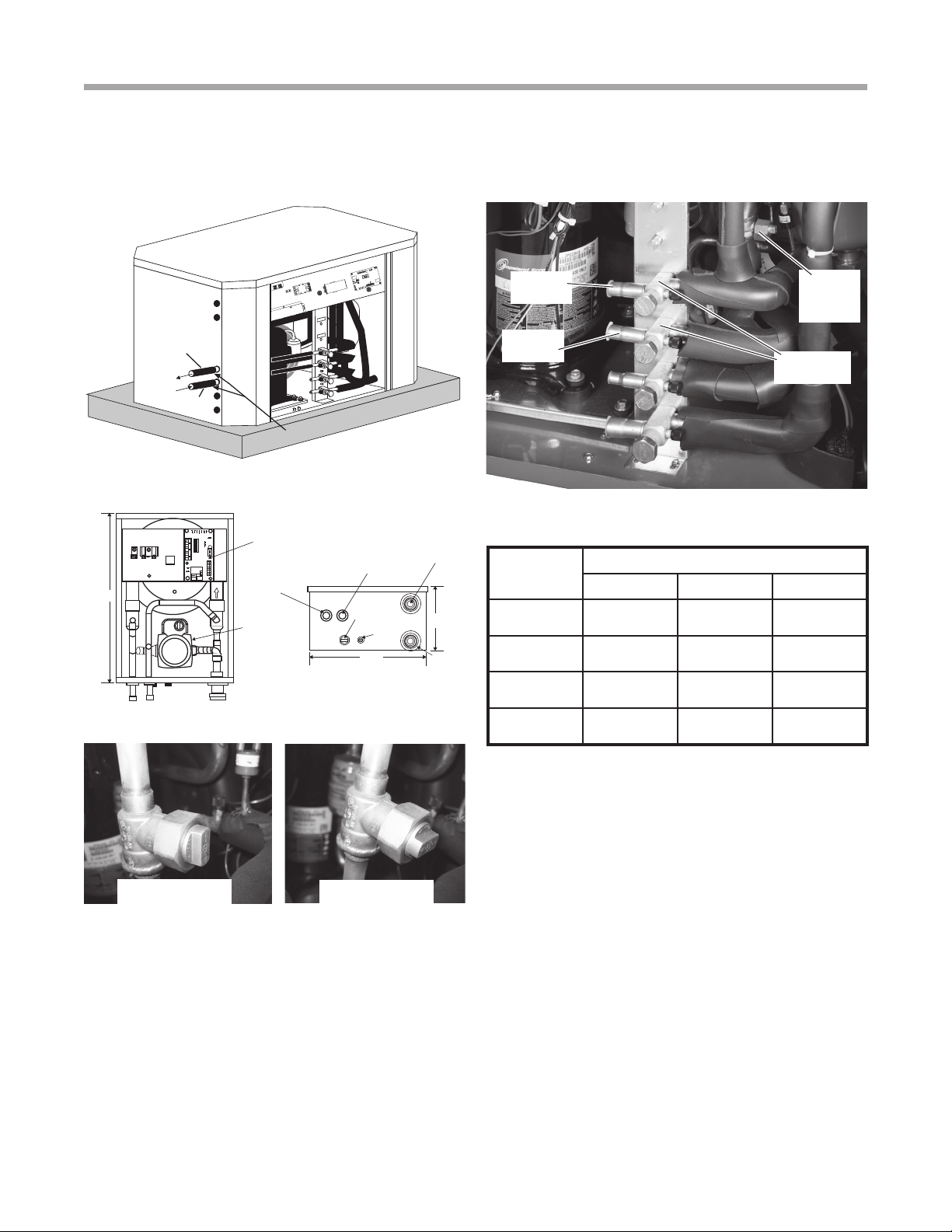
Figure 3a: Outdoor Compressor Section HWG Installation
Fully Insulated
Lines to the HWG
Refr to
HWG
Refr from
HWG
Figure 4: HWG Refrigerant Line Sizing
Figure 3b: Remote HWG Module
Figure 3c: HWG Service Valves
Figure 3d: HWG Bypass Valve
Valve Open
(HWG Bypassed)
Valve Closed
(HWG Activated)
Control
Board
Circulator
HWG
Water Out
HWG
Refr Out
HWG
Refr In
High Voltage
HWG
Water In
16.2”
11.1”
7.1”
Low
Voltage
HWG
Water In
Capacity Line Set Size
1/2” OD 5/8” OD 3/4” OD
2 Ton Up to 16 ft.
[4.9m]
Up to 30 ft.
[9.1m] N/A
3 Ton Up to 9 ft.
[2.7m]
Up to 25 ft.
[7.6m]
Up to 30 ft.
[9.1m]
4 Ton Up to 5 ft.
[1.5m]
Up to 13 ft.
[4.0m]
Up to 30 ft.
[9.1m]
5 Ton N/A Up to 9 ft.
[2.7m]
Up to 25 ft.
[7.6m]
As a guideline add 1.0 oz. of refrigerant for the heat exchang-
er plus 1.0 oz. for each 10 ft of 1/2” OD refrigerant line, if the
weighed charge method is used (28g for the heat exchanger
plus 9g per meter of 1/2” OD refrigerant line).
HWG
Line Valves
HWG
Bypass
Valve
Refr
to HWG
Refr from
HWG

7
Remote HWG
Rev.: Februrary 10, 2016
climatemaster.com
Hot Water Generator Module
The microprocessor control monitors the refrigerant and
water temperatures to determine when to operate the HWG.
The HWG will operate any time the refrigerant temperature
is suciently above the water temperature. Once the
HWG has satised the water heating demand during a
heat pump run cycle, the controller will cycle the pump at
regular Intervals to determine if an additional HWG cycle
can be utilized. The microprocessor control Includes 3 DIP
switches, SW10 (HWG PUMP TEST), SW11 (HWG TEMP),
and SW12 (HWG STATUS).
SW10 HWG PUMP TEST. When this switch is in the “ON”
position, the HWG pump is forced to operate even if there
is no call for the HWG. This mode may be benecial to
assist in purging the system of air during Initial start up.
When SW10 is in the “OFF” position, the HWG will operate
normally. This switch is shipped from the factory in the
“OFF” (normal) position. NOTE; If left in the “On” position for
5 minutes, the pump control will revert to normal operation.
SW11 HWG TEMP. The control setpoint of the HWG can
be set to either of two temperatures, 125°F or 150°F. When
SW11 is in the “ON” position the HWG setpoint is 150°F.
When SW11 is in the “OFF” position the HWG setpoint is
� WARNING! �
� WARNING! �
WARNING!
UNDER NO CIRCUMSTANCES SHOULD
THE SENSORS BE DISCONNECTED OR REMOVED
AS FULL LOAD CONDITIONS CAN DRIVE HOT
WATER TANK TEMPERATURES FAR ABOVE SAFE
TEMPERATURE LEVELS IF SENSORS HAVE BEEN
DISCONNECTED OR REMOVED.
WARNING!
USING A 150°F SETPOINT ON THE
HWG WILL RESULT IN WATER TEMPERATURES
SUFFICIENT TO CAUSE SEVERE PHYSICAL INJURY
IN THE FORM OF SCALDING OR BURNS, EVEN
WHEN THE HOT WATER TANK TEMPERATURE
SETTING IS VISIBLY SET BELOW 150°F. THE
150°F HWG SETPOINT MUST ONLY BE USED ON
SYSTEMS THAT EMPLOY AN APPROVED ANTI-
SCALD VALVE (CLIMATEMASTER PART NUMBER
AVAS4) AT THE HOT WATER STORAGE TANK
WITH SUCH VALVE PROPERLY SET TO CONTROL
WATER TEMPERATURES DISTRIBUTED TO ALL HOT
WATER OUTLETS AT A TEMPERATURE LEVEL THAT
PREVENTS SCALDING OR BURNS!
125°F. This switch Is shipped from the factory in the “OFF”
(125°F) position.
SW12 HWG STATUS. This switch controls operation of
the HWG. When SW12 is in the “ON” position the HWG is
disabled and will not operate. When SW12 is in the “OFF”
position the HWG is in the enabled mode and will operate
normally. This switch is shipped from the factory in the
“ON” (disabled) position. CAUTION: DO NOT PLACE THIS
SWITCH IN THE ENABLED POSITION UNITL THE HWG
PIPING IS CONNECTED, FILLED WITH WATER, AND
PURGED OR PUMP DAMAGE WILL OCCUR.
When the control is powered and the HWG pump output
is not active, the status LED (AN1) will be “On”. When the
HWG pump output is active for water temperature sampling
or HWG operation, the status LED will slowly ash (On 1
second, O 1 second).
If the control has detected a fault, the status LED will ash a
numeric fault code as follows:
Hot Water Sensor Fault 1 ash
Compressor Discharge sensor fault 2 ashes
High Water Temperature (>160ºF) 3 ashes
Control Logic Error 4 ashes
Fault code ashes have a duration of 0.4 seconds with
a 3 second pause between fault codes. For example, a
“Compressor Discharge sensor fault” will be four ashes
0.4 seconds long, then a 3 second pause, then four ashes
again, etc.
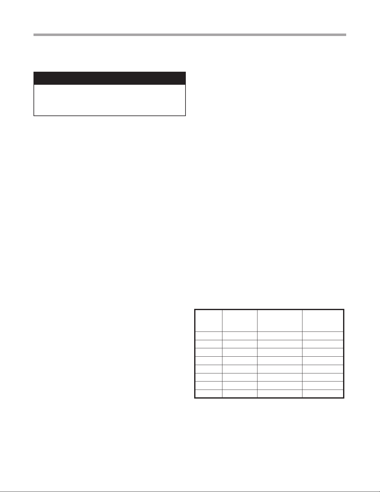
C
H
M
WATER HEATER
CHECK VALVE
8” MA X
HOT WATER
TO HOUSE
ANTI-SCALD
VALVE
ANTI-SCALD
VALVE PIPING
CONNECTIONS
COLD WATER
SUPPLY
Installation
The HWG is controlled by two sensors and a microprocessor
control. One sensor is located on the compressor discharge
line to sense the discharge refrigerant temperature. The
other sensor is located on the HWG heat exchanger’s “Water
In” line to sense the potable water temperature.
Remote HWG
Rev.: Februrary 10, 2016
8Geothermal Heat Pump Systems
Hot Water Generator Module - Domestic Water Installation
The heat pump, water piping, HWG, and hot water tank
should be located where the ambient temperature does
not fall below 50°F [10°C]. Keep water piping lengths at a
minimum. DO NOT use a one way length greater than 50 ft.
(one way) [15 m].
All installations must be in accordance with local codes. The
installer is responsible for knowing the local requirements,
and for performing the installation accordingly. DO NOT
connect the pump wiring until “Initial Start-Up” section,
below. Powering the pump before all installation steps are
completed may damage the pump.
Water Tank Preparation
1. Turn o power or fuel supply to the hot water tank.
2. Connect a hose to the drain valve on the water tank.
3. Shut o the cold water supply to the water tank.
4. Open the drain valve and open the pressure relief valve
or a hot water faucet to drain tank.
5. When using an existing tank, it should be ushed with
cold water after it is drained until the water leaving the
drain hose is clear and free of sediment.
6. Close all valves and remove the drain hose.
7. Install HWG water piping.
HWG Water Piping
1. Using at least 5/8” [16mm] O.D. copper, route and install
the water piping and valves as shown in Figures 1 or 2.
Install an approved anti-scald valve if the 150°F HWG
setpoint is or will be selected. An appropriate method
must be employed to purge air from the HWG piping.
This may be accomplished by ushing water through the
HWG (as In Figures 1 and 2) or by Installing an air vent at
the high point of the HWG piping system.
2. Insulate all HWG water piping with no less than 3/8”
[10mm] wall closed cell insulation.
3. Open both shut o valves and make sure the tank drain
valve is closed.
Water Tank Rell
1. Close valve #4. Ensure that the HWG valves (valves #2
and #3) are open. Open the cold water supply (valve #1)
to ll the tank through the HWG piping. This will purge air
from the HWG piping.
2. Open a hot water faucet to vent air from the system until
water ows from faucet; turn o faucet. Open valve #4.
3.
Depress the hot water tank pressure relief valve handle to
ensure that there is no air remaining in the tank.
4. Inspect all work for leaks.
5.
Before restoring power or fuel supply to the water heater,
� WARNING! �
adjust the temperature setting on the tank thermostat(s)
to insure maximum utilization of the heat available from
the refrigeration system and conserve the most energy.
On tanks with both upper and lower elements and
thermostats, the lower element should be turned down
to 100°F [38°C] or the lowest setting; the upper element
should be adjusted to 120-130°F [49-54°C]. Depending
upon the specic needs of the customer, you may want
to adjust the upper element dierently. On tanks with a
single thermostat, a preheat tank should be used (Fig 2).
6. Replace access cover(s) and restore power or
fuel supply.
Initial Start-Up
1. Make sure all valves in the HWG water circuit are fully
open.
2. Make electrical connections (power and low voltage)
as shown on the HWG wiring diagram. Example wiring
diagrams and an electrical data table are included in this
document (See Figures 5-8).
3. Turn the heat pump power and remote HWG power “o”
and switch dip switch SW12 on the HWG controller to the
“o” (enabled) position to activate the HWG.
4. The HWG pump should not run if the compressor is not
running.
5. The temperature dierence between the water entering
and leaving the HWG should be approximately 5-10 °F
[3-6 °C].
6. Allow the unit to operate for 20 to 30 minutes insure that
it is functioning properly.
7. Always turn dip switch SW12 on the HWG controller to
the “on” (disabled) position to deactivate the HWG when
servicing the outdoor compressor section.
Warning! Use extreme caution when working around
the microprocessor control as it contains line voltage
connections that presents a shock hazard that can
cause severe injury or death!
HWG Water Piping Size and Length
Unit
Nominal
Tonnage
Nominal
HWG Flow
(gpm)
1/2" Copper
(max length*)
3/4" Copper
(max length*)
1.5 0.6 50 -
2.0 0.8 50 -
2.5 1.0 50 -
3.0 1.2 50 -
3.5 1.4 50 -
4.0 1.6 45 50
5.0 2.0 25 50
6.0 2.4 10 50
*Maximum length is equivalent length (in feet) one way of type L
copper.
9
Remote HWG
Rev.: Februrary 10, 2016
climatemaster.com
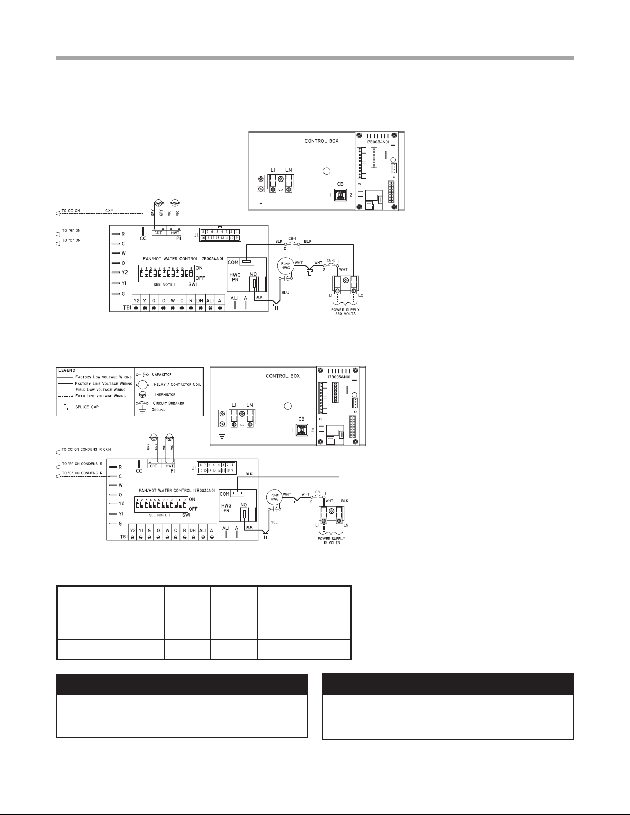
Electrical - Wiring
Figure 5: HWG Module Wiring 230 Volt
HWG Module Wiring - For
“Outdoor” Compressor Section
The HWG module should be wired to
a power supply as shown in Figure
5 or 6. A safety disconnect should
be installed at the HWG module as
required by code to allow servicing
of the module. DO NOT energize
the pump until all HWG piping is
completed and air is purged from
the water piping to avoid running the
pump “dry”.
� WARNING! �� CAUTION! �
HWG
Module Voltage Pump
FLA Total FLA
Min
Circuit
Amps
Min Wire
Size
AHWG1AASS 115/60/1 0.52 0.52 1.20 14 ga.
AHWG1AGSS 208/230/60/1 0.40 0.40 0.90 14 ga.
Figure 7: HWG Module Electrical Data
CONDENSER
HWG Module
CONDENSER
CONDENSER
E
E
E
Figure 6: HWG Module Wiring 115 volt
WARNING! To avoid possible injury or death due to
electrical shock, open the power supply disconnect switch
and secure it in an open position during installation.
CAUTION! Use only copper conductors for eld installed
electrical wiring. Unit terminals are not designed to accept
other types of conductors.
Remote HWG
Rev.: Februrary 10, 2016
10 Geothermal Heat Pump Systems
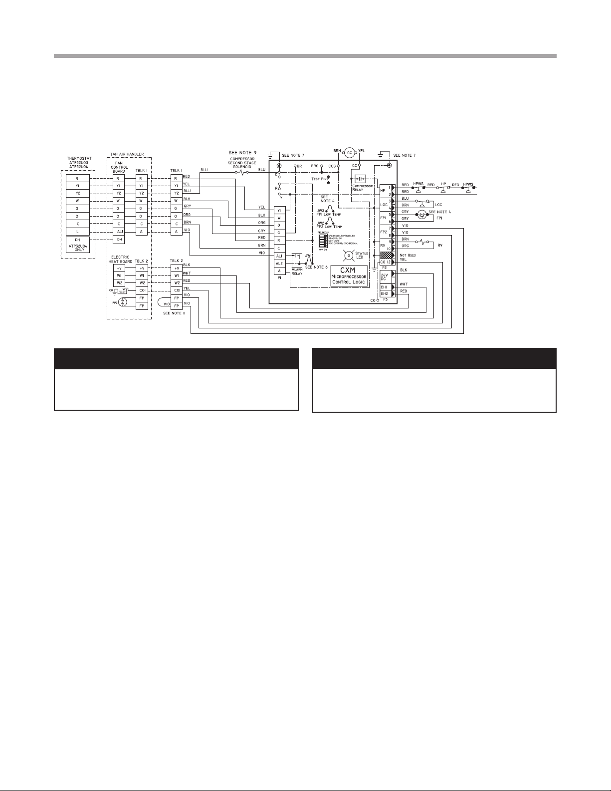
Figure 8: Low Voltage Field Wiring
� WARNING! �� CAUTION! �
Electrical - Wiring
WARNING! To avoid possible injury or death due to
electrical shock, open the power supply disconnect switch
and secure it in an open position during installation.
CAUTION! Use only copper conductors for eld installed
electrical wiring. Unit terminals are not designed to accept
other types of conductors.
11
Remote HWG
Rev.: Februrary 10, 2016
climatemaster.com
Warranty
CLIMATE MASTER, INC.
LIMITED EXPRESS WARRANTY AND LIMITATION OF LIABILITY AND
REMEDIES FOR RESIDENTIAL CLASS PRODUCTS WITH LABOR ALLOWANCE
This Limited Express Warranty And Limitation Of Liability And Remedies Affects Your Legal Rights And Should Be Read Carefully In Its Entirety.
Subject to the terms and conditions below, Climate Master, Inc. (“CM”) extends a limited warranty (“Limited Warranty”) for Residential Class heating and cooling equipment manufactured or sold by CM (“Products”), that was purchased on or after May 1, 2010 (this would generally include
CM Units with serial numbers beginning with “N118” and higher), and installed in a one or two family residential dwelling, for personal, household or family purposes in the United States of America or Canada, (“Application”), to be free from defects and workmanship under normal use and
maintenance. If you are unsure if this Limited Warranty applies to a Product you have purchased, contact CM at the phone number or address reected below.
This Limited Warranty DOES NOT cover commercial applications of the Products. Commercial applications include any application other than installation in a one or two family residential dwelling for personal, household or family purposes. Refer to ClimateMaster Commercial Limited Express
Warranty for details. Full copies are available for download at ClimateMaster.com .
This Limited Warranty provides a complete statement of CM’s responsibilities to purchasers of the Products. No oral or written statement made by CM, any person or entity associated with CM or by any person or entity claiming to be associated with CM, including but not limited to statements
made in sales literature, catalogs, or agreements to purchase or install the Products, is intended to provide an express or implied warranty of any kind and does not form a part of the basis of the bargain. Further, no such statement shall operate to extend, alter or modify the scope or terms of this
Limited Warranty.
EXCEPT AS SPECIFICALLY SET FORTH HEREIN, THERE IS NO EXPRESS WARRANTY AS TO ANY OF CM’S PRODUCTS. CM MAKES NO WARRANTY AGAINST LATENT DEFECTS, OF MERCHANTABILITY OF THE PRODUCTS OR OF THE PRODUCTS
FOR ANY PARTICULAR PURPOSE.
TERM: This Limited Warranty shall commence on the earliest to occur of the following dates: (i) proof of date of rst occupancy; (ii) proof of date of start-up of the Product by a qualied and trained HVAC contractor; or (iii) six (6) months from the shipment date of the Product from CM if items
(i) or (ii) are not available (“Warranty Inception Date”). The Limited Warranty shall extend as follows:
Costs of Repair or Replacement of Covered Product Parts
(1) Ten (10) years from the Warranty Inception date for air conditioning, heating and/or heat pump units built or sold by CM (“CM Units”);
(2) Ten (10) years from the Warranty Inception Date for thermostats, auxiliary electric heaters, water storage tanks, and geothermal pumping modules built or sold by CM, when installed with CM Units;
(3) One (1) year from the date of shipment from CM for any other accessories or parts built or sold by CM, when installed with CM Units; and
(4) Ninety (90) days from the date of shipment from CM for all repair or replacement parts that are not supplied under this warranty.
Costs of Labor to Install Repaired or Replaced Covered Product Parts
(1) Five (5) years from the Warranty Inception Date for CM Units;
(2) Five years from the Warranty Inception Date for thermostats, auxiliary electric heaters, water storage tanks, and geothermal pumping modules built or sold by CM, when installed with CM Units
This Limited Warranty does not cover labor costs for installation of other accessories or parts built or sold by CM or any repaired or replacement parts that are not supplied under this Limited Warranty.
WHO IS COVERED: This Limited Warranty is provided only to the original owner of the one or two family residential dwelling in which the Products are rst installed. This Limited Warranty is not transferrable. CM reserves the right to request any documentation necessary in its sole discretion
to determine the date of purchase and occupancy of the residential dwelling or the date of installation and start-up of the Product(s). For the avoidance of any doubt, this Limited Warranty shall not extend to, and shall provide no remedies whatsoever for, any distributor or installer of the Products.
CLAIM PROCESS: To make a claim under this warranty, the Product or parts must be returned to CM in Oklahoma City, Oklahoma, freight prepaid, no later than ninety (90) days after the date of the failure of the part. If CM determines the Product or part to be defective and covered by this
Limited Warranty, CM will either repair or replace the Product or part and send it to a CM-recognized distributor, dealer or service organization, F.O.B. CM, Oklahoma City, Oklahoma, freight prepaid. The Limited Warranty on any Product or part repaired or replaced under this Limited Warranty
extends only through the original warranty period.
WHAT IS COVERED: Subject to the Term, this Limited Express Warranty covers the: (i) the cost of repair or replacement of any covered Product or Product parts; and (ii) the cost of labor incurred by CM authorized service personnel in connection with the installation of a repaired or replaced
covered Product or Product part.
If a Product part is not available, CM will, at its option, provide a free suitable substitute part or provide a credit in the amount of the then factory selling price for a new suitable substitute part to be used by the claimant towards the retail purchase price of a new CM product. All labor costs are
subject and limited to amounts specically set forth in the then existing labor allowance\ schedule provided by CM’s Warranty Department. Actual labor costs are not covered by this Limited Warranty to the extent they: (i) exceed the amount allowed under the allowance schedule; (ii) are not
specically provided for in the allowance schedule; (iii) are not performed by CM authorized service personnel; (iv) are incurred in connection installation of a part not covered by this Limited Warranty; or (v) are incurred outside the Term.
WHAT IS NOT COVERED: This Limited Warranty does not cover and does not apply to: (1) air lters, fuses, refrigerant, uids, oil; (2) Products relocated after initial installation; (3) any portion or component of any system that is not supplied by CM, regardless of the cause of the failure of
such portion or component; (4) Products on which the unit identication tags or labels, or rating labels, have been removed or defaced; (5) Products on which payment to CM, or to the owner’s seller or installing contractor, is in default; (6) Products which have not been installed and maintained by
a qualied and trained HVAC contractor; (7) Products installed in violation of applicable building codes or regulations including but not limited to wiring or voltage conditions; (8) Products subjected to accident, misuse, negligence, abuse, re, ood, freezing, lightning, unauthorized alteration,
misapplication, contaminated or corrosive air or liquid supply, operation at abnormal air or liquid temperatures or ow rates, or opening of the refrigerant circuit by unqualied personnel; (9) mold, fungus or bacteria damages; (10) corrosion or abrasion of the Product; (11) products supplied by
others; (12) Products that have been operated in a manner contrary to CM’s printed instructions; (13) Products which have insufcient performance as a result of improper system design, sizing or the improper application, installation, or use of CM’s products; (14) electricity or fuel costs, or any
increases or unrealized savings in same, for any reason whatsoever; or (15) operating any water storage tanks when they are empty or partially empty (i.e. dry ring), at temperatures exceeding the maximum setting of the operating or high limit controls, at pressures greater than those shown on the
rating label, with non-potable water, with alterations or attachments (including energy savings devises) not specically authorized in writing by CM, or without the free circulation of water. CM may request written documentation showing compliance with the above limitations.
In connection with repair or replacement of covered Product parts, CM is not responsible for: (1) the costs of any uids, refrigerant or system components supplied by others, or associated labor to repair or replace the same, which is incurred as a result of repair or replacement of a covered Product
part; (2) the costs of labor, refrigerant, materials or service incurred in diagnosis and removal of a covered Product part subject to repair or replacement under this Limited Warranty; (3) shipping costs incurred in sending a claimed defective part from the installation site to CM; (4) shipping costs to
return a claimed defective part from CM to the installation site if the part is not covered by this Limited Warranty; (5) removal or disposal costs associated with the repair or replacement of covered Product Parts; or (6) the costs of normal maintenance.
OTHER WARRANTY LIMITATION: This Limited Warranty is given in lieu of all other warranties express or implied, in law or in fact. If, notwithstanding the disclaimers contained herein, it is determined that other warranties apply, any such warranty, including without limitation any express
warranties or any implied warranties of tness for particular purpose and merchantability, shall be limited in time to the Term of this Limited Warranty
LIMITATION OF REMEDIES: In the event of a breach of the Limited Warranty, a claimant’s remedies will be limited to repair or replacement of a part or unit, or to furnish a new or rebuilt part or unit in exchange for the part or unit which has failed. If after written notice to CM’s factory
in Oklahoma City, Oklahoma of each defect, malfunction or other failure, and a reasonable number of attempts by CM to correct the defect, malfunction or other failure, the remedy fails of its essential purpose, CM shall refund the purchase price paid to CM in exchange for the return of the
sold good(s). Said refund shall be the maximum liability of CM. THIS REMEDY IS THE SOLE AND EXCLUSIVE REMEDY OF THE BUYER OR THEIR PURCHASER AGAINST CM FOR ANY ACTION FOR BREACH OF CONTRACT, BREACH OF ANY WARRANTY, PATENT
INFRINGEMENT, OR FOR CM’S NEGLIGENCE OR IN STRICT LIABILITY. NO ACTION ARISING OUT OF ANY CLAIMED BREACH OF THIS LIMITED WARRANTY MAY BE BROUGHT MORE THAN ONE (1) YEAR AFTER THE CAUSE OF ACTION HAS ARISEN.
LIMITATION OF LIABILITY: CM shall have no liability for any damages if CM’s performance is delayed for any reason or is prevented to any extent by any event such as, but not limited to: any war, civil unrest, government restrictions or restraints, strikes, or work stoppages, re, ood,
accident, shortages of transportation, fuel, material, or labor, acts of God or any other reason beyond the sole control of CM.
CM EXPRESSLY DISCLAIMS AND EXCLUDES ANY LIABILITY FOR CONSEQUENTIAL, INCIDENTAL, SPECIAL AND/OR PUNITIVE DAMAGES BASED ON ANY THEORY IN CONTRACT, BREACH OF ANY EXPRESS OR IMPLIED WARRANTY, PATENT
INFRINGEMENT, OR IN TORT, WHETHER FOR CM’s NEGLIGENCE OR AS STRICT LIABILITY AND REGARDLESS OF WHETHER CM IS ADVISED OF THE POSSIBILITY OF SUCH DAMAGES.
OBTAINING WARRANTY PERFORMANCE: Normally, the dealer or service organization who installed the products will provide warranty performance for the owner. Should the installer be unavailable, contact any CM recognized distributor, dealer or service organization. If assistance is
required in obtaining warranty performance, write or call:
Climate Master, Inc. • Customer Service • 7300 SW 44th Street • Oklahoma City, Oklahoma 73179 • (405) 745-6000 • e-service@climatemaster.com
NOTE: Some states or Canadian provinces do not allow the exclusion or limitation of implied warranties or the limitation of incidental or consequential damages for certain products supplied to consumers, or the limitation of liability for personal injury, so the above limitations and exclusions
may be limited in their application to you. When the implied warranties are not allowed to be excluded in their entirety, they will be limited to the duration of the applicable written warranty. This warranty gives you specic legal rights, which may vary depending on local law. IF ANY PRODUCT
TO WHICH THIS LIMITED WARRANTY APPLIES IS DETERMINED TO BE A “CONSUMER PRODUCT” UNDER THE MAGNUSON-MOSS WARRANTY ACT (15 U.S.C.A. §2301, ET SEQ.) OR OTHER APPLICABLE LAW, THE FOREGOING DISCLAIMER OF IMPLIED
WARRANTIES SHALL NOT APPLY TO YOU, AND ALL IMPLIED WARRANTIES ON THIS PRODUCT, INCLUDING WARRANTIES OF MERCHANTABILITY AND FITNESS FOR THE PARTICULAR PURPOSE, SHALL APPLY FOR THE SAME TERM SET FORTH ABOVE
(ONE YEAR) AS PROVIDED UNDER APPLICABLE LAW. The portions of this Limited Warranty and limitation of liability shall be considered fully severable, and all portions which are not disallowed by applicable law shall remain in full force and effect.
This warranty gives you specic legal rights, and you may also have other rights which vary from state to state and from Canadian province to Canadian province. Refer to your local laws for your specic rights under this Limited Warranty.
Please refer to the CM Installation, Operation and Maintenance Manual for operating and maintenance instructions.
Rev.: 3/20
Part No.: RP851
Remote HWG
Rev.: Februrary 10, 2016
12 Geothermal Heat Pump Systems
Revision History
97B0080N01
ClimateMaster works continually to improve its products. As a result, the design and specications of each product at the time for order may be
changed without notice and may not be as described herein. Please contact ClimateMaster’s Customer Service Department at 1-405-745-6000
for specic information on the current design and specications. Statements and other information contained herein are not express warranties
and do not form the basis of any bargain between the parties, but are merely ClimateMaster’s opinion or commendation of its products.
© ClimateMaster, Inc. 2009
*97B0080N01*
Rev.: Feb. 10, 2016
7300 S.W. 44th Street
Oklahoma City, OK 73179
Phone: 405-745-6000
Fax: 405-745-6058
climatemaster.com
Date Page # Description
10 Feb, 16 12 Updated certication logos
27 July, 10 10 Low Voltage Field Wiring Figure Updated
4 May, 10 11 New Warranty Update
30 April, 10 4 HWG Piping Drawings Revised
20 Oct., 09 All Verbiage Updates
19 August, 09 All First Published
This manual suits for next models
2
Table of contents
Other ClimateMaster Control Unit manuals

Popular Control Unit manuals by other brands

EasyIO
EasyIO FD-20i Series User reference

Moxa Technologies
Moxa Technologies CA Series user manual

Puls
Puls YR20.246 manual

JETStream
JETStream 53905 Product instructions

Telit Wireless Solutions
Telit Wireless Solutions LE920 Hardware user's guide

STIEBEL ELTRON
STIEBEL ELTRON SOKI 7 E plus Operation and installation

Pentair
Pentair FLECK 2850 SXT user guide

Bauerfeind
Bauerfeind Uniprox V08 instruction manual

Emerson
Emerson KTM 2-WAY Installation, operation and maintenance instructions

Cooper
Cooper LCMD-10 installation guide

Baldor
Baldor 23H Series Installation & operating manual

Infineon
Infineon IM393 Series Application note


