manuals.online logo
Brands
  1. Home
  2. •
  3. Brands
  4. •
  5. Cooper
  6. •
  7. Control Unit
  8. •
  9. Cooper LCMD-10 User manual

Cooper LCMD-10 User manual

Typical Schematic
LCMD-10
DALI Lighting Control Module
Installation Guide
Cooper Lighting Solutions
Usk House, Lakeside
Llantarnam Park,
Cwmbran,
NP44 3HD, UK
t: +44 (0)1923 495495
e: [email protected]
www.
cooperlightingsolutions.co.uk
Doc No: 9850-000754-01
E&OE. iLight reserve the
right to make changes to the
equipment without prior notice.
© Cooper Lighting Solutions
FM 664349
LCMD-10 must be securely mounted to a suitable surface using the 4 mounting holes provided with xings
suitable for the substrate (Maximum xing diameter 6mm). The LCM can be mounted in any orientation to
cable trays, walls and direct to a ceiling slab. All cables should be independantly secured with appropriate
xing straps in accordance with local electrical regulations. Incoming mains, data and input cables should
be installed using suitable compression cable glands to provide strain relief.
Once securely mounted,
remove cover using a
at-head screwdriver
to access the wiring
compartment. Gently tilt
the screwdriver towards
the top (connectors) of
LCM to release.
Mounting Hole
Mounting Hole350mm Hole Centres
170mm Hole Centres
Mounting Hole
Mounting Hole
Mounting & Installation Technical Data
Electrical Data
Supply: 230 volts -/+ 10%, 50/60 Hz
Terminals max. wire size: 4mm2loop in/out
iCANnet™ inputs/output: 5 pole Phoenix connector
Maximum DALI cable length: 300m per LCM
Minimum DALI cable conductor diameter: 1.5mm2
Protection: Provided by installer - Max 16A
DALI signal: Nominal 16V, max current 200mA supply.
Guaranteed minimum current 150mA
Automatic shut-down and restart after short-circuit
(maximum 1 per bus) according to IEC 62386-101
Inputs & Outputs
10 ports with 6 pole GST/18 connectors
4 x RJ12 analogue sensor inputs
Max 30 DALI luminaires (or short addresses) distributed at will
across 10 ports
In addition: 1 DALI sensors per port,
1 DALI control plate or DALI-I-U per port
1 DALI emergency luminaire per port
Mechanical Data
Dimensions: 200.2mm (w) x 382.8mm (h) x 57.5mm (d)
Maximum diameter of xings: 6mm
Weight: 2.5 kg
Operating Conditions
Operating temperature: +2ºC to +50ºC
Max storage temperature: +60ºC
Humidity: +5 to 95% non-condensing
Environmental protection: IP20
Removing Knockouts
The knockouts can be removed with a at-head
screwdriver in 2 simple steps:
1. Place the at-head screwdriver into the slot of the
knockout that is to be removed. The screwdriver must be
placed in the slot nearest to the bottom of the enclosure
(opposite the cover).
2. Hit the end of the screwdriver to shear the knockout and
remove the rest of the knockout by hand if necessary.
Alternatively an appropriate sized hole saw can be used
utilising the drill bit location point at the centre of each
knockout.
EU Authorised Representative
Cooper Lighting Netherlands B.V.
High Tech Campus
HTC 48
Eindhoven
5656 AE
230V and DALI
230V and DALI
DALI
Control Plate
DALI
Control Plate
DALI
Combined Sensor
DALI
High Bay Sensor
DALI
Drivers / Ballasts
DALI
Emergency Luminaire
iCAN Network
230V Supply
LCMD-10
Third Party
Light Switch
Key Switch
9850-000754-01. E&OE.
Incoming Supply
230 volts -/+ 10%, 50/60 Hz
Mains supply protection:
Provided by installer (16A Max)
Status LED
Data LED
Alarm LED
iLight Network
Connection
via RJ45
Sensor Inputs
1
2
3
4
Device Identication Button (IDENT)
SW-L
Earth
Neutral
Maintained Live
DA+
DA-
iLight Network
Connection
Switched
Inputs
Supply
DALI
Status LED
Green LED ashes – device OK
Data LED
Red LED ashes when messages sent on network
Red LED solid indicates iCANnet network error
Alarm LED
Red LED ashes ON for local initiated alarm
Red LED solid for network initiated alarm
Device Identication (IDENT)
By pressing the IDENT button
Device LEDs and Buttons
Typical Connection Diagram
LCMD-10
DALI Lighting Control Module
Function iCANnet Cable Colours
0V Black
CAN L Blue
Shield Silver
CAN H White
+VDC Red
Maximum segment distance: 500m (1640 ft)
Devices per segment: 100 (without bridge or repeater)
Consult iLight for information on alternative cable types. Input 1&2: 2 position retractive switch:
1- ‘local LCM’ short press = On
and ‘press and hold’ = Dim up.
2- ‘local LCM’ short press = Off
and ‘press and hold’ = Dim down.
Input 3: Keyswitch for network emergency
test set/release.
Input 4: Latching switch for network
integrity test set/release. (Sets all outputs
on all connected LCMs to On or Off).
iCAN Network Connections
Network Power Requirements
Nominal operating voltage: 15VDC (12-18V)
IMPORTANT NOTE: Connecting a mains potential cable to the
iCAN Network terminals is likley to damage the unit and other
devices connected, and invalidate warranty.
IMPORTANT NOTE: If the external luminaire requires a protective
earth for safety purposes then a protective earth must be installed
during the installation process by a qualied installation engineer/
electrician to the local/national regulations. LCMD-10 does not
provide a protective earth.

Other Cooper Control Unit manuals

Cooper Scantronic 65 User manual

Cooper

Cooper Scantronic 65 User manual

Cooper Scantronic 9 5 Series User manual

Cooper

Cooper Scantronic 9 5 Series User manual

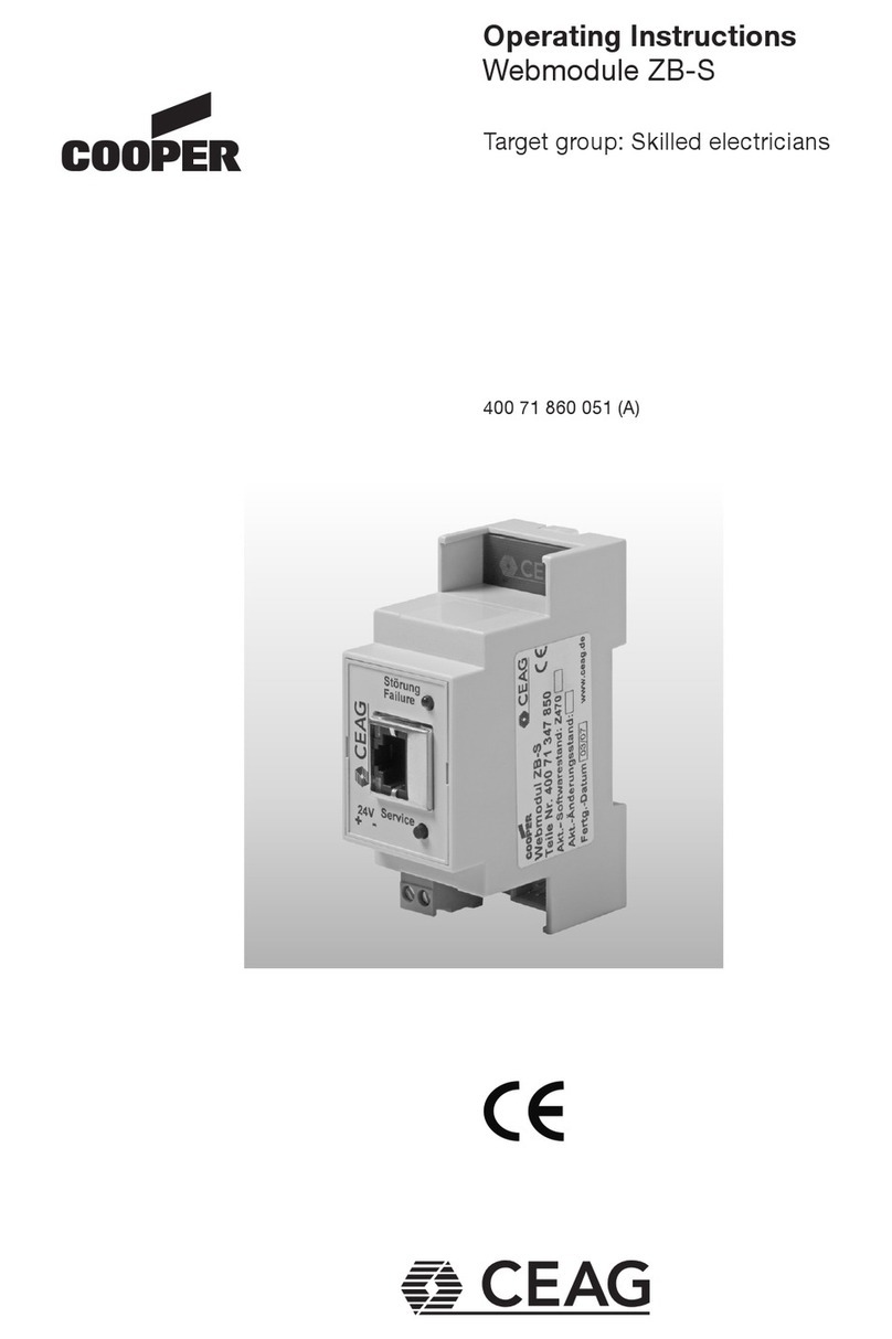
Cooper CEAG Webmodule ZB-S User manual

Cooper

Cooper CEAG Webmodule ZB-S User manual

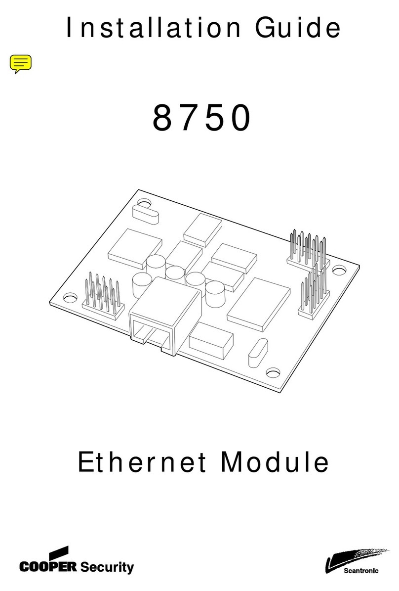
Cooper Scantronic 8750 User manual

Cooper

Cooper Scantronic 8750 User manual

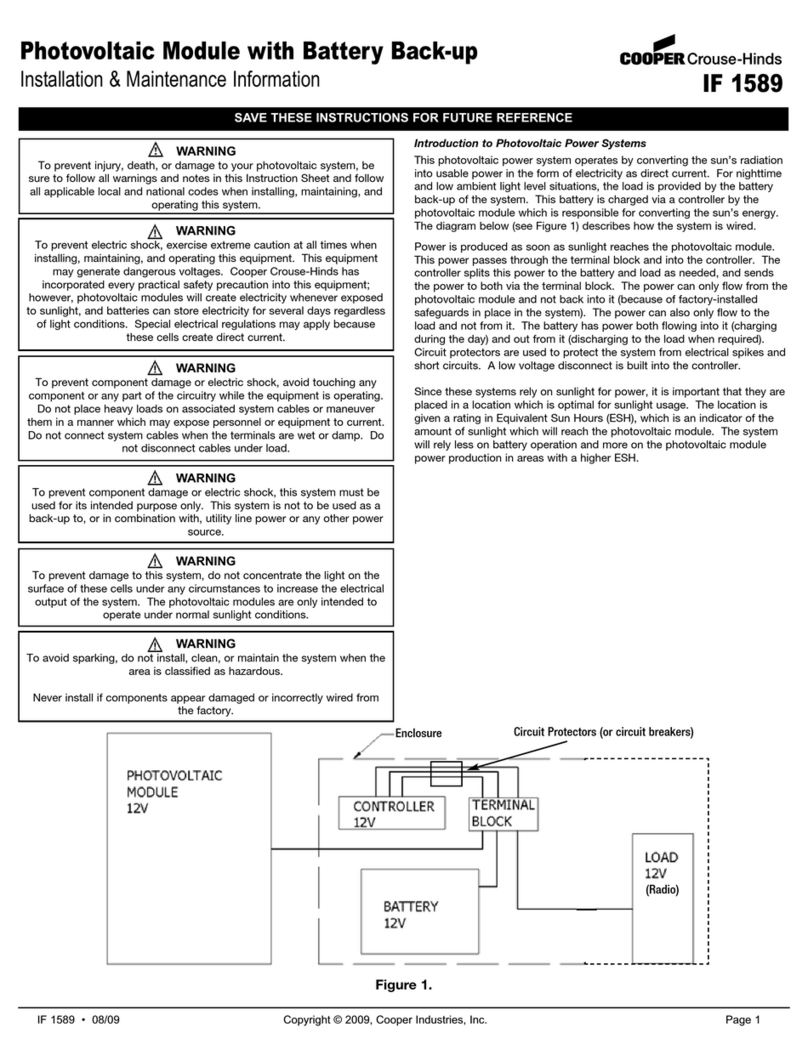
Cooper Crouse-Hinds IF 1589 Setup guide

Cooper

Cooper Crouse-Hinds IF 1589 Setup guide

Cooper 9930 User manual

Cooper

Cooper 9930 User manual

Cooper Scantronic 9 5 Series Operating instructions

Cooper

Cooper Scantronic 9 5 Series Operating instructions

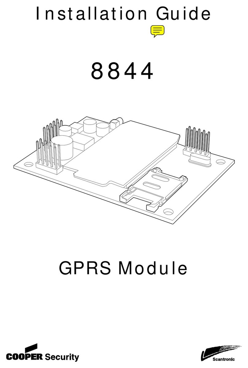
Cooper Scantronic 8844 User manual

Cooper

Cooper Scantronic 8844 User manual

Cooper Scantronic 95 User manual

Cooper

Cooper Scantronic 95 User manual

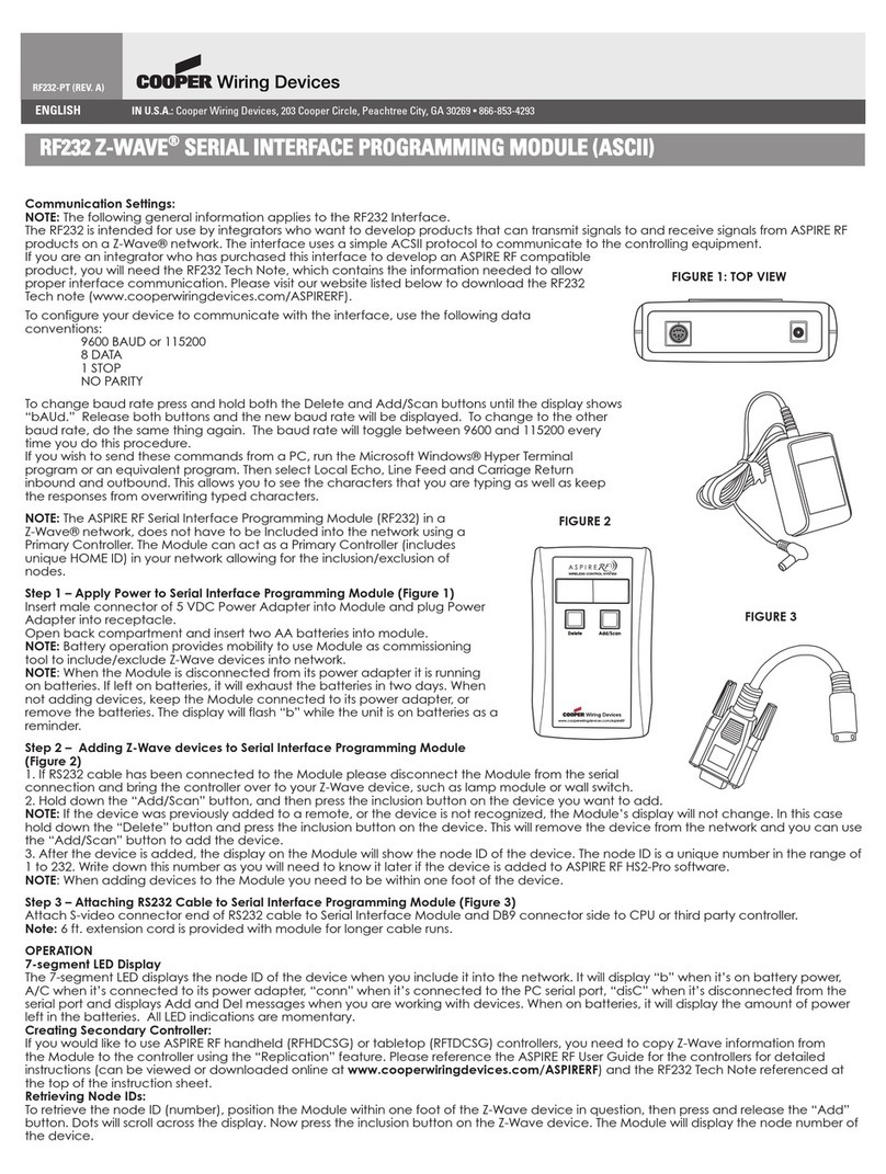
Cooper Z-WAVE RF232 User manual

Cooper

Cooper Z-WAVE RF232 User manual

Cooper Scantronic 770r User manual

Cooper

Cooper Scantronic 770r User manual

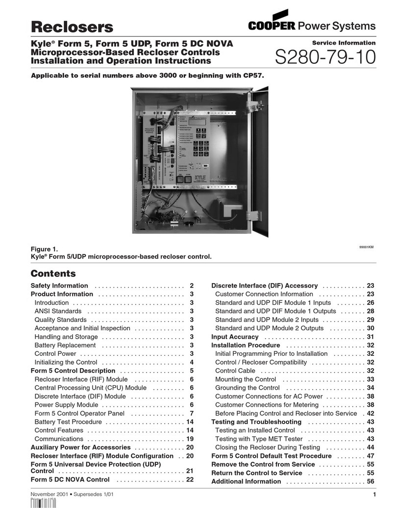
Cooper S280-79-10 User manual

Cooper

Cooper S280-79-10 User manual

Cooper F6-PA-LS User manual

Cooper

Cooper F6-PA-LS User manual

Popular Control Unit manuals by other brands

Frequency Central Waverider VCDO MKii Build documentation

Frequency Central

Frequency Central Waverider VCDO MKii Build documentation

Lenze EMZ9374IB operating instructions

Lenze

Lenze EMZ9374IB operating instructions

Burkert 2006 operating instructions

Burkert

Burkert 2006 operating instructions

Omnitron Systems Technology Omnitron iConverter 10/100M2 quick start guide

Omnitron Systems Technology

Omnitron Systems Technology Omnitron iConverter 10/100M2 quick start guide

JYTEK JY5312 user manual

JYTEK

JYTEK JY5312 user manual

IEI Technology IVC-168G Quick installation guide

IEI Technology

IEI Technology IVC-168G Quick installation guide

GMMC NFC NUTSHELL KIT user manual

GMMC

GMMC NFC NUTSHELL KIT user manual

urmet domus Yokis MEP2000E manual

urmet domus

urmet domus Yokis MEP2000E manual

Siemens OMM-1 installation instructions

Siemens

Siemens OMM-1 installation instructions

Kilsen KAL714C Installation sheet

Kilsen

Kilsen KAL714C Installation sheet

JAUDT FS140-6115 Series Translation of the original operating instructions

JAUDT

JAUDT FS140-6115 Series Translation of the original operating instructions

ATB ATB-control 3 installation instructions

ATB

ATB ATB-control 3 installation instructions

Watts Tekmar 305V installation manual

Watts

Watts Tekmar 305V installation manual

Nibe SMO S40 user manual

Nibe

Nibe SMO S40 user manual

thermital TBOX BASIC R Installation, operation and maintenance manual

thermital

thermital TBOX BASIC R Installation, operation and maintenance manual

Rotex 31123 Mounting, Operating, Testing & Maintenance Instructions

Rotex

Rotex 31123 Mounting, Operating, Testing & Maintenance Instructions

Pepperl+Fuchs VAA-2E-KE1-S Original instructions

Pepperl+Fuchs

Pepperl+Fuchs VAA-2E-KE1-S Original instructions

Evco C-PRO 3 CLIMA sistema+ Installer manual

Evco

Evco C-PRO 3 CLIMA sistema+ Installer manual

manuals.online logo
manuals.online logoBrands
  • About & Mission
  • Contact us
  • Privacy Policy
  • Terms and Conditions

Copyright 2025 Manuals.Online. All Rights Reserved.