INSTALLATION & GENERAL SAFETY INFORMATION
● Unit Designed for indoor usage only. Do not submerge or spray water on the portable air conditioner.
● Do not use the unit at conditions above 95°F in cooling mode
● Use 115V-60HZ, 1Phase power supply only. Securely plug into grounded 15amp
outlet.
● Do not use an extension cord which may cause a risk of fire or electric shock.
● Do not bend or kink power cable. Damage to power cord can cause electric shock
or injury.
● Do not place anything on the top of the machine. Do not stand or place hands or
fingers inside of the unit while in operation.
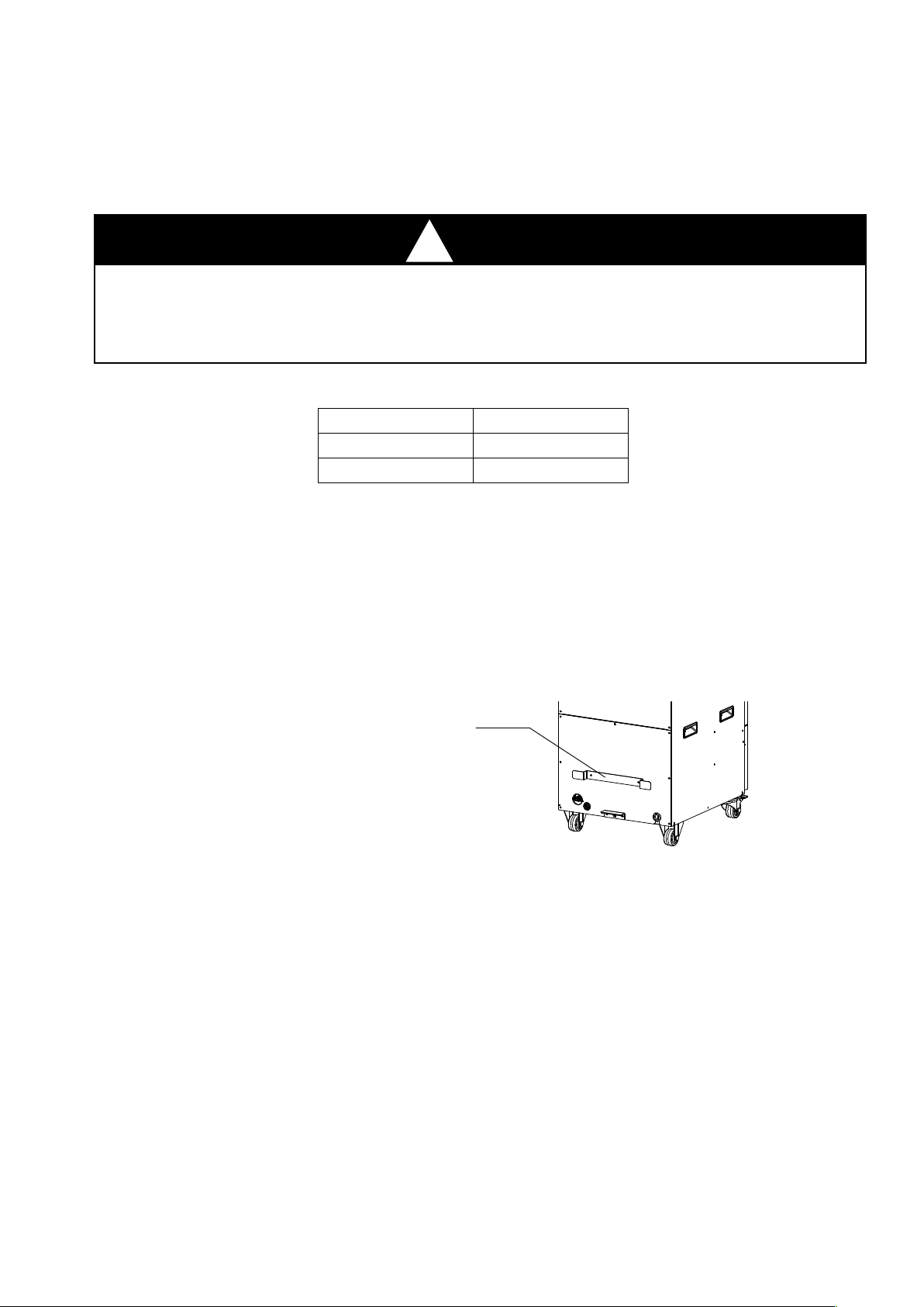
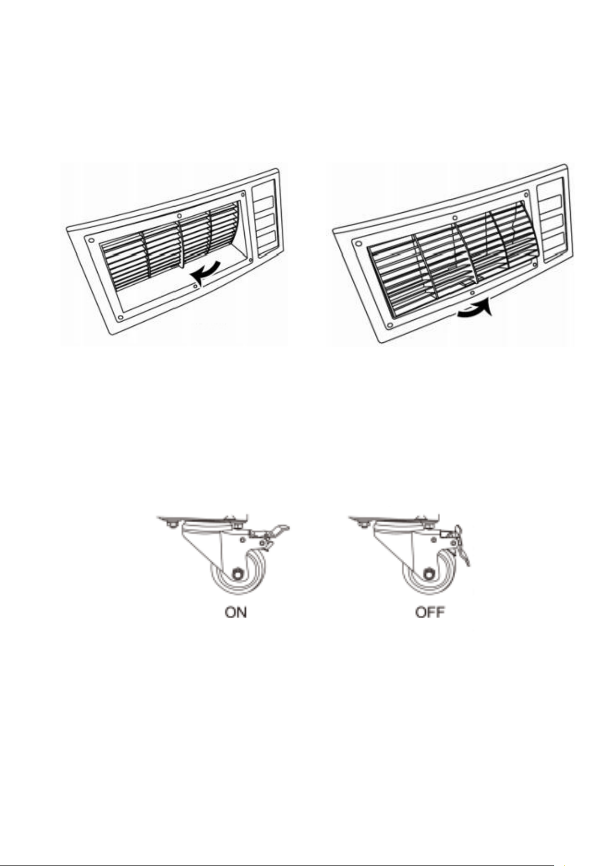
● Install unit on smooth level ground. Lock the castors breaks to minimize rolling
and movement.
● Always power off unit by the control panel, do not turn off by removing plug from
power source.
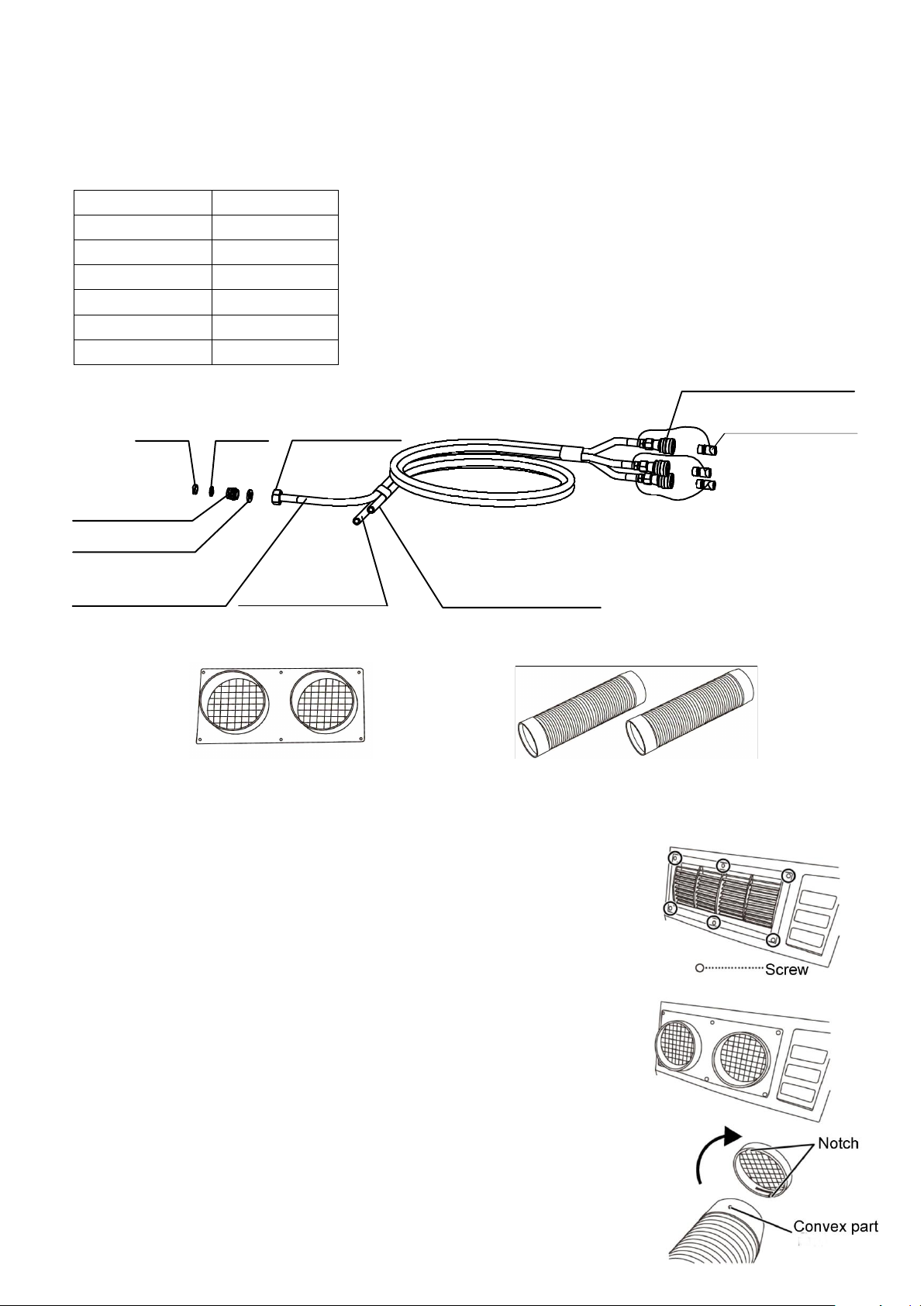
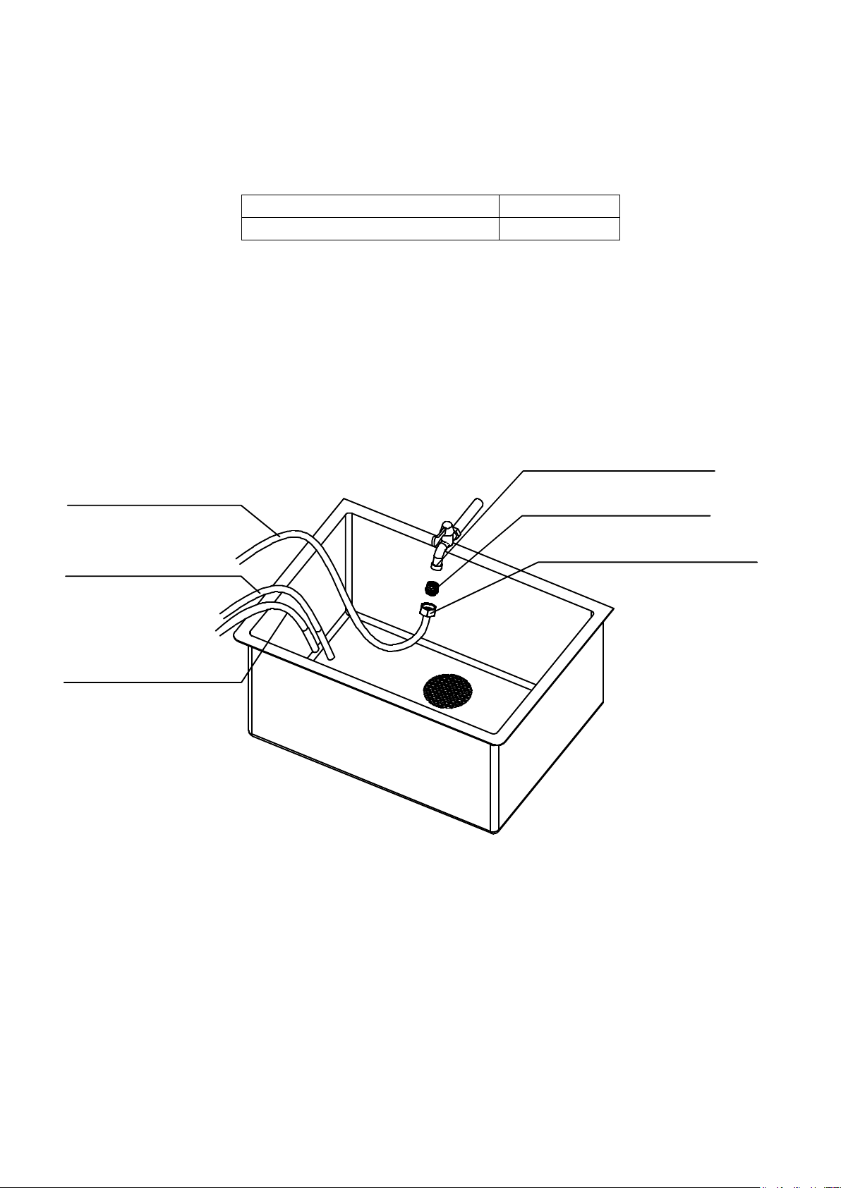
●Make sure all quick connections are secure and not leaking
●After hose kit connections are made, supply only cold water to the unit. Unit will not operate with hot water supply.
Additional Precautions:
•Please place the machine out of the reach of children.
•Do not store the machine in a place with high temperature, rain or direct sunlight.
•Do not store the machine horizontally or upside down. Always keep upright.
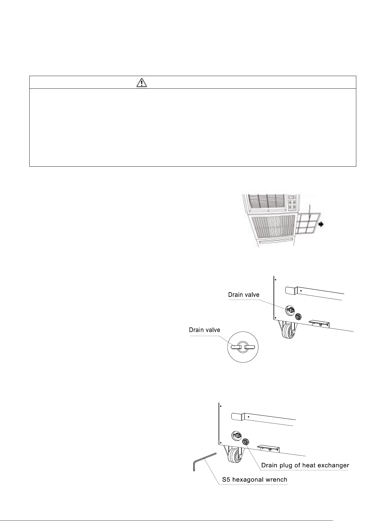
•When keeping and storing the machine, be sure to cut off the power supply
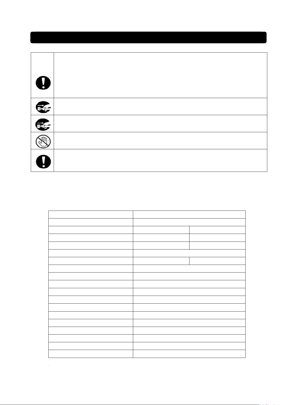
For safety, please observe
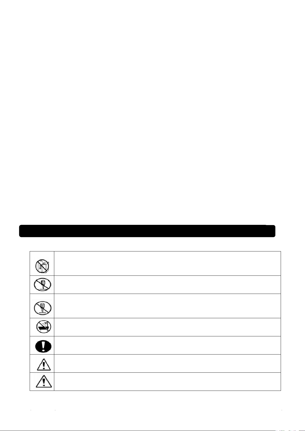
In places where volatile substances (such as diluent, gasoline, kerosene, liquefied gas and other
volatile liquids, aluminum, magnesium, lead and other volatile dusts and vapors) are used or
stored, please never use the air conditioner, which may cause fire, explosion, fire and burns.
Please do not modify the unit, which may cause damage to the machine, or even fire.
Except for professional repair personnel, other personnel should not repair or disassemble to
avoid fire, electric shock, injury and other safety accidents. If repair is needed, please contact
your authorized ClimaTemp Distributor.
Please do not use outside or in places with rain, and do not use wet hands. Unit is not outdoor
rated.
Please use single-phase 110V power supply. If a power supply other than 110V is used, the
machine will be damaged.
The electrical installation must be carried out by professionals in accordance with the equipment
standards and wiring regulations, otherwise safety accidents may occur
Please use it within the specified operating range of 64° F~113° F, otherwise unit will not operate.