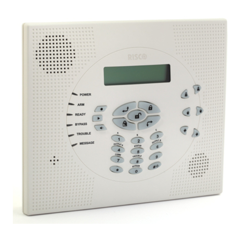
Climax Technology HSGW-Gen2-V1 User manual

HSGW-Gen2-V1
IP Alarm System
User Manual
August 19, 2022
Certified by Telefication BV
Manufacturer: Climax Technology, Taiwan
Type: HSGW-Gen2-V1
Compliance with Standard:
EN50131-3:2009 / EN50131-6:2017 /
EN50131-5-3:2017 / EN50130-4:2011+A1:2014 /
EN50131-10:2014 / EN50136-2:2013 /
EN 50130-5:2011, Security Grade 2
Environmental Class II
CIE Type A

Table of Contents
1.INTRODUCTION _________________________________________________________________________ 1
1.1. SYSTEM SPECIFICATION _____________________________________________________________________ 1
1.2. PACKAGE CONTENT ________________________________________________________________________ 3
2.PANEL INFORMATION ___________________________________________________________________ 4
2.1. IDENTIFYING THE PARTS: ____________________________________________________________________ 4
2.2. THE POWER SUPPLY: _______________________________________________________________________ 5
2.3. SYSTEM REQUIREMENTS: ____________________________________________________________________ 5
3.GETTING STARTED ______________________________________________________________________ 6
3.1. HARDWARE INSTALLATION __________________________________________________________________ 6
3.2. CONNECT TO PANEL ________________________________________________________________________ 8
4. DEVICE MANAGEMENT ____________________________________________________________________ 12
4.1. LEARNING ______________________________________________________________________________ 12
4.2. SENSOR MANAGEMENT ____________________________________________________________________ 14
5. PANEL MANAGEMENT _____________________________________________________________________ 17
5.1. ARMING SETTING _________________________________________________________________________ 18
5.2. SOUND SETTING __________________________________________________________________________ 19
5.3. MONITORING STATION SETTINGS _____________________________________________________________ 20
5.4. TIMER _________________________________________________________________________________ 21
5.5. TROUBLE CONDITION SETTING ______________________________________________________________ 21
5.6. USER CODES ____________________________________________________________________________ 22
5.7. WI-FI SETTING ___________________________________________________________________________ 23
5.8. MISCELLANEOUS SETTING __________________________________________________________________ 23
6. SYSTEM SETTINGS ________________________________________________________________________ 24
6.1 CENTRAL STATIO N REPORTING _______________________________________________________________ 24
5.2.ENABLING EN GRADE 2/INCERT MONITORING _____________________________________________ 25
5.3.DATE AND TIME ______________________________________________________________________ 26
6.4. CHANGE PASSWORD _______________________________________________________________________ 28
7. NETWORK ________________________________________________________________________________ 31
7.1. CELL AND IP COMMUNICATION ______________________________________________________________ 31
8. SYSTEM OPERATION ______________________________________________________________________ 33
8.1 FAULTS AND TAMPERS ______________________________________________________________________ 33

8.2 VIEW HISTORY ___________________________________________________________________________ 35
8.3 HISTORY ________________________________________________________________________________ 36
8.4. REQUESTING A FIRMWARE UPGRADE __________________________________________________________ 37
8.5 SYSTEM OPERATION AND MAINTENANCE _______________________________________________________ 37
8.5.1 Device Test________________________________________________________________________ 37
8.5.2 IP/GSM reporting __________________________________________________________________ 37
9.AUTOMATION DEVICES ________________________________________________________________ 40
9.1. DEVICE LEARNING AND OPERATION __________________________________________________________ 40
10. APPENDIX _______________________________________________________________________________ 41
APPENDIX A: SENSOR GROUPS __________________________________________________________________ 41
APPENDIX B: FAULTS _________________________________________________________________________ 43

1
1. Introduction
HSGW-Gen2-V1 is a fixed wall mounting wireless alarm system control panel. It is designed to
protect your home by forming an alarm system with various wireless sensors. When an intruder
is detected, the wireless sensor will transmit signal to the control panel to raise an alarm and
report to the Central Monitoring Station.
HSGW-Gen2-V1 features RF and Z-Wave wireless protocol for communication with accessory
devices. The RF devices are simple and easy to use while the Z-Wave devices, using
corresponding network, is capable of performing more advanced function and add flexibility to
alarm system such as using Remote Keypad to control system mode, view alarm memory and
event log, or capturing alarm pictures using PIR Camera to send to panel wirelessly for alarm
visual verification.
Integrating IP, GSM, Z-Wave and RF for multi-path reporting, HSGW-Gen2-V1 features a
user-friendly webpage for the user to connect via Local Area Network for easy programming and
control.
1.1. System Specification
Function
Zone Number 160 Wireless Zones
Area Number 2
Zone Types Start Entry Delay, Burglar Follow, Burglar Instant, Burglar
Outdoor, 24 Hours, Fire, Medical, Emergency, Emergency
(Quiet), Water, Set/Unset, Silent Panic, CO, Gas, Heat
For information on configuring Zone Groups, please see
Appendix A
User PIN Codes 6 Users, 1 PIN Code each user (6-digits, number 0~9), available
combination from 000002~999999 (999998 different
combinations, 000000 and 000001 are disallowed).
Note: Input of 5 invalid User PIN codes at the remote keypad will
lock the remote keypad for 15 minutes.
Control Facilities Remote Keypad & Remote Controller
A
larm.com Server Webpages
Report Destinations 20 Monitoring Stations or mobile number
Reporting Format Contact ID, SIA, SMS Text,
Arming Modes Away, Home 1, Home 2, Home 3
Alarm Type Burglar, Panic, Fire, Medical, Emergency, Water, Silent
Siren Timeout Programmable (3 min. by default), For Remote Keypad use only

2
Supervision Programmable time frame for inactivity alert
Special Function Tamper Protection
GSM Standards Compiles with CE standards
EN Classification EN Grade 2 Class II
Alarm Transmission Path Dual Path: DP1 (EN50136-1:2012)
Supported RCT Alarm Report Server (ARS), Fibro, OH200, MasterMind, Manitou,
MicroKey and SIA DC 09
Mode of
Acknowledgement
Operation.
Pass-through (EN50136-2:2013, Clause 6.1.3)
Memory DDR3L SDRAM: 512Mbyte
eMMC : 4GByte
Electrical
Power Source Built-in switching power supply, 100-240V, 50/60Hz input, 12V
1.5A output
Power Supply Type PS Type A, not suitable for use external to supervised premises.
Backup Battery 7.2V, NiMH 600mAh AAA rechargeable battery pack (built-in)
APS fault Low Voltage SD
signal threshold 7.3 V ± 3%
Battery Duration 14 hours
Battery Recharge Time to
80% of 600mAH 72 hours
Minimum Energy Level of
Backup Battery 86%
Current Drain AC Powered Average. 126mA/12V standby
839mA/12V full load
Battery Powered Average. 42mA/7.2V standby
876mA/7.2V full load
Wireless
WCDMA Frequency B1/B2/B5/B8
LTE Frequency B1/B2/B3/B4/B5/B7/B8/B28/B40
RF Frequency 433.82MHz

3
Z-Wave Frequency 908.4/916/919.8/921.4M
Antenna Type GSM: Main – PIFA; AUX – Dipole
ZW: Monople
RF: Monople
Encryption Private Encryption Method
Protocol Climax
Physical Properties
Operating Temperature -10°C to 45°C (14°F to 113°F)
Humidity 50 ~ 85% relative humidity @23°C, non-condensing
Size 185mm x 185mm x 50mm
Weight 580g (Includes backup battery)
1.2. Package Content
1 x HSGW-Gen2-V1 Control Panel
1 x AC Power Cord for Built-in S.P.S (12V 1.5A)
1 x Installation and Instruction Manual
4 x Screws and Wall Plug for wall mounting

4
2. Panel Information
2.1. Identifying the parts:
Front Cover view Side View Back View
1 LED 1 - Area 1 (Green/Red)
Full Arm mode - Red lighting up
Home/1/2/3 mode - Red flashing
Disarm mode - Green lighting up
Walk Test or Learning mode - Green flashing
2 LED 2 - Area 2 (Green/Red)
Full Arm mode - Red lighting up
Home/1/2/3 mode - Red flashing
Disarm mode - Green lighting up
Walk Test or Learning mode - Green flashing
3 LED 3 - Status (Orange/Red)
System Fault - Orange lighting up
Alarm Trigger – Red flashing
Alarm in Memory – Red lighting up
4 Speaker
5 Micro SIM Card Compartment
6 USB Port
7 Learn/Reset Button
8 Ethernet Port
9 Battery Switch (slide to “ON” to meet requirements of the applicable EN standard.)
10 Internal Cover
11 Buzzer
12 Tamper Switch
The panel is protected by an internal tamper switch which is compressed when the panel is
Mounting Bracket

5
hooked onto the mounting bracket. When the panel is removed from the mounting bracket,
the tamper switch will be activated and the panel will send a tamper open signal to remind
the user of this condition.
13
Power Cord Inlet
14
Wiring Hole
15
Fixing Screws x 2
16
Wall Mounting Holes x 2
17
Mounting Bracket
2.2. The Power Supply:
Built-in Power Supply
Built-in Switching Power Supply (S.P.S) is installed in the Control Panel. You can use the
AC Power Cord for Built-in S.P.S to connect to the mains power.
Please note:
Ensure to turn off all power supplies including the built-in power supply and
battery before connecting or removing cables or wires.
Rechargeable Battery
There is a rechargeable battery inside the Control Panel, which serves as a backup in case
of a power failure.
The battery switch for the rechargeable battery must be switched ON for the Control Panel
to meet requirements of the applicable EN standard.
During normal operation, the built-in switching power supply is used to supply power to the
Control Panel and at the same time recharge the battery.
<NOTE>
If the AC power is missing and the battery is near exhaustion, a low battery message
will be displayed and the internal siren will be disabled to conserve power.
When the AC power is restored, the low battery message will be dismissed.
2.3. System Requirements:
The Control Panel requires a TCP/IP network environment to access its webpage for
programming and control. To view the Control Panel webpage, your computer must have:
Microsoft Windows 8 or Windows 10 operating system, or later
Google Chrome 104 or Mozilla Firefox 103, or later.
CPU: Intel Pentium II 266MHz or above
Memory: 32MB (64MB recommended)
VGA resolution: 800x600 or above

6
3. Getting Started
Read this section of the manual to learn how to set up your HSGW-Gen2-V1 Panel and program
System Settings over the Web page.
3.1. Hardware Installation
The panel can be either fixed on the wall or placed on deskop. For the panel to meet
requirements of the applicable EN standard, wall mounting installation must be used.
1 Remove the 2 screws that secured the panel casing to the mounting bracket. (Figure 1)
2 Remove the mounting bracket to reveal the back cover fixing screw. (Figure 2)
Figure 1
Figure 2
3 Remove the screw securing the back cover (as circled in Figure 2).
4 Set up the Control Panel though the following steps:
I. Connect Ethernet cable to panel Ethernet port.
II. Insert a functional micro SIM Card into Micro SIM Card Compartment, the SIM Card
PIN Code must be disabled first.
III. Slide Battery Switch to ON position.
IV. Use the AC Power Cord for Built-in S.P.S to to connect to the mains power.
5 Wire the cable, close the back cover and secure it by fastening the screw. Proceed to
mount the panel onto the wall.

7
Wall Mounting: (EN Compliance)
I. Use the mounting holes as template, mark mounting locations on the wall.
II. Secure the mounting bracket onto the wall by tightening the 2 screws through the wall
mounting holes.
III. Mount the Control Panel with the hooks of the mounting bracket latched onto the back
cover of the the panel, and push it downward until you hear a clicking sound.
Make sure the tamper switch is properly compressed against the hook of the
mounting bracket. Then fasten the 2 bottom fixing screws to complete the installation.
Push

8
3.2. Connect to Panel
Step 1. Connect to https://alarmadmin.alarm.com/mobile/Default.aspx and log in with provided
username and password
Step 2. In the main page, select “Find Customer”.

9
Step 3. Select “Recent Customers” to expand.
Step 4. Select the panel account you with to access.
<IMPORTANT NOTE>
The Installer Access function must be granted by user first to enable installer functions.
By default, Installer Access is granted for 6 hours per session.
After logging into the Installer App, if there is no activity for 10 minutes, the installers
session will timeout and the rep will be logged out of the application.

10
Step 5. You will access the panel user’s customer information.
<IMPORTANT NOTE>
The Installer Access function must be enabled by user first, otherwise login attempt will
fail.
To enable user access, ask the user to follow steps below:
I. Go to https://www.alarm.com/login.aspx and login with the user account information.

11
II. Select “Profile” – “Manage Logins” – “Edit Dealer Setting”.
III. Set “Installer Access” to “”On” then save the setting.
<IMPORTANT NOTE>
After 20 minutes of inactivity on the Customer App, the user’s session will timeout and
the user will need to log in again to use any functions.

12
4. Device Management
Under Customer Info page, select “Equipment” to for device management.
4.1. Learning
Step 1. Under Equipment page, select “Add Devices”.

13
Step 2. Select the device type from the menu. For example, select “Sensor”
Step 3. The Panel will begin to enter learning mode.
Step 4. After the panel has entered learning mode, activate the device to send signal to panel.

14
Step 5. When the panel receives sensor signal, the sensor info will be displayed on webpage.
Add any additional devices and click “Exit and Edit” to proceed to next step.
4.2. Sensor Management
The Sensor Management page can be accessed either after finish adding new device, or by
selecting “Sensor” – “Sensor Management” under Equipment page.
Under the Sensor Management page, choose to edit device name, sensor group and
activity monitoring, the click Save to confirm. Sensor Group allows the configuration of
the sensors as different Zone types. Please see Appendix A for descriptions of Sensor
Groups.
<NOTE>
For
EN Grade 2 Compliance, the Activity Monitoring box may NOT be checked. Without
Sensor Activity Monitoring, Automation rules will still function, however sensor based
Notifications from Alarm.com will not work.

15
The sensor partition can be edited by selecting “Advanced Sensor Settings”. Choose
new partition for the device and click “Save Changes” to confirm.
Click “Add Sensor” to learn new sensors, see 4.1. Learning for detail.
Click “Delete Sensor” to remove device, you will enter device removal page. Select the
device to be removed and click “Send Command” to confirm.
Click “Walk Test” to access Walk Test function. The Walk Test function allows you to
test signal strength of the device.
I. Click “Begin Walk Test” to put panel into Walk Test Mode.
II. When the panel is under Walk Test mode, activate a learnt in device to send signal
to Panel.

16
III. When the panel receives signal from panel, the webpage info will be updated with
sensor info. After finish testing all sensor, click End Walk Test to exit Walk Test
Mode.

17
5. Panel Management
Under Customer Info page, select “Panel/Partitions” – “Panel Management” to access panel
management page.
Click each option to expand the setting for configuration
<NOTE>
For EN Grade 2 Compliance, the following Panel Management Settings must be
configured:
Auto-Phone Test: 6 hrs.
Supervision Timer: 2 hrs.
Swinger Shutdown: 3
Ethernet Bypass: Disabled
AC Fail Report Timer: 5 minutes
Dialer Delay: 0
Table of contents
Other Climax Technology Security System manuals
